Page is loading ...

Miller
December1994
Form:
OM-1582F
Effective
With
Serial
No.
KF759252
OWNERS
MANUAL
Read
and
follow
these
instructions
and
all
safety
blocks
carefully.
Have
only
trained
and
qualified
persons
install,
operate,
or
service
this
unit.
Call
your
distributor
if
you
do
not
understand
the
directions.
~
U
Give
this
manual
to
the
operator.
~i~i]
For
help,
call
your
distributor
or:
MILLER
Electric
Mfg.
Co.,
P.O.
Box
1079,
Appleton,
WI
54912
414-734-9821
D-62
And
D-64
24
Volts
AC,
10
Amperes,
50/60
Hertz
Wire
Feeder
For
Use
With
CV/DC
Welding
Power
Source
With
Contactor
For
GMAW
And
FCAW
Welding
Rated
At
100
Volts,
750
Amperes,
100%
Duty
Cycle
Circuit
Breaker
CB1
Protects
Unit
From
Overload
Wire
Feed
Speed
Range:
50
To
780
ipm
(1.3
To
20
mpm)
Wire
Diameter
Range:
.023
To
1/8
in
(0.6
To
3.2
mm)
For
Options
And
Accessories,
See
Rear
Cover
cover
5/94
ST-143
327-A
'
1994
MILLER
Electric
MIg.
co.
PRINTED
IN
USA

Within
the
warranty
periods
listed
below,
MILLER
will
repair
or
replace
any
war
ranted
parts
or
components
that
fail
due
to
such
defects
in
material
or
workmanship.
MILLER
must
be
notified
in
writing
within
thirty
(30)
days
of
such
defect
or
failure,
et
which
lime
MILLER
will
provide
instructions
on
the
warranty
claim
procedures
to
be
followed.
MILLER
shall
honor
warranty
claims
on
warranted
equipment
listed
below
in
the
event
of
such
a
failure
within
the
warranty
lime
periods.
All
warranty
lime
periods
start
on
the
dale
that
the
equipment
was
delivered
to
the
original
retail
purchaser,
or
one
year
aher
the
equipment
is
sent
to
a
North
American
distributor
or
eighteen
months
after
the
equipment
is
sent
to
an
Intemationat
distributor.
1.
5
Years
Parts
3
Years
Labor
Original
main
power
rectifiers
2.
3
Years
Parts
and
Labor
Transformer/Rectifier
Power
Sources
*
Plasma
Arc
Cutting
Power
Sources
Semi-Automatic
and
Automatic
Wire
Feeders
Robots
3.
2 Years
Pans
and
Labor
Engine
Driven
Welding
Generators
(NOTE:
Engines
are
warranted
separately
by
the
engine
manufacturer
for
a
period
of
two
years.)
Air
Compressors
4.
1
Year
Pans
and
Labor
Motor
Driven
Guns
Process
Controllers
Water
Coolant
Systems
HF
Units
Grids
Spot
Welders
Load
Banks
SDX
Transformers
Running
Gear/Trailers
Plasma
CuBing
Torches
(escept
APT,
ZIPCUT
&
PLAZCUT
Models)
Field
Options
(NOTE:
Field
options
are
covered
under
True
BIueTM
for
the
remaining
warranty
period
of
the
product
they
are
installed
in,
or
for
a
minimum
of
one
year
whichever
is
greater.)
5.
6
Months
Batteries
6.
90
Days
Pans
and
Labor
MIG
Guns/TIG
Torches
APT,
ZIPCUT
&
PLAZCUT
Model
Plasma
Cusing
Torches
1.
Items
furnished
by
MILLER,
but
manufactured
by
others,
such
as
engines
or
trade
accessories.
These
items
are
covered
by
the
manufacturers
warranty,
if
any.
2.
Consumable
components;
such
as
contact
tips,
cuBing
nozzles,
costactors
and
relays
or
pans
that
fail
due
to
normal
wear.
3.
Equipment
that
has
been
modified
by
any
party
other
than
MILLER,
or
equip
ment
that
has
been
improperly
installed,
improperly
operated
or
misused
based
upon
industry
standards,
or
equipment
which
has
not
had
reasonable
and
necessary
maintenance,
or
equipment
which
has
been
used
for
operation
outside
of
the
specifications
for
the
equipment.
MILLER
PRODUCTS
ARE
INTENDED
FOR
PURCHASE
AND
USE
BY
COMMER
CIAL/INDUSTRIAL
USERS
AND
PERSONS
TRAINED
AND
EXPERIENCED
IN
THE
USE
AND
MAINTENANCE
OF
WELDING
EGUIPMENT.
In
the
event
of
a
warranty
claim
covered
by
this
warranty,
the
esclusive
remedies
shall
be,
at
MILLERS
option:
(1)
repair:
or
(2)
replacement:
or,
where
authorized
in
writing
by
MILLER
in
appropriate
cases,
(3)
the
reasonable
cost
of
repair
or
replace
ment
stan
authorized
MILLER
service
station;
or
(4)
payment
of
or
credit
for
the
pur
chase
price
(less
reasonable
depreciation
based
upon
actual
use)
upon
retum
of
the
goods
af
customers
risk
and
expense.
MILLERS
option
of
repair
or
replacement
will
be
FOB.,
Factory
at
Appleton,
Wisconsin,
or
FOB.
eta
MILLER
authorized
ser
vice
facilily
es
determined
by
MILLER.
Therefore
no
compensation
or
reimburse
ment
for
transportation
costs
of
any
kind
will
be
allowed.
TO THE EXTENT
PERMITTED
BY
LAW,
THE
REMEDIES
PROVIDED
HEREIN
ARE
THE
SOLE
AND
EXCLUSIVE
REMEDIES.
IN
NO
EVENT
SHALL
MILLER
BE
LIABLE
FOR
DIRECT,
INDIRECT,
SPECIAL,
INCIDENTAL
OR
CONSEOUENTIAL
DAMAGES
(INCLUDING
LOSS
OF
PROFIT),
WHETHER
BASED
ON
CON
TRACT,
TORT
OR
ANY
OTHER
LEGAL
THEORY.
ANY
EXPRESS
WARRANTY
NOT
PROVIDED
HEREIN
AND
ANY
IMPLIED
WAR
RANTY,
GUARANTY
OR
REPRESENTATION
AS
TO
PERFORMANCE.
AND
ANY
REMEDY
FOR
BREACH
OF
CONTRACT
TORT
OR
ANY
OTHER
LEGAL
THEORY
WHICH,
BUT
FOR
THIS
PROVISION,
MIGHT
ARISE
BY
IMPLICATION,
OPERATION
OF
LAW,
CUSTOM
OF
TRADE
OR COURSE
OF
DEALING,
IN
CLUDING
ANY
IMPLIED
WARRANTY
OF
MERCHANTABILITY
OR
FITNESS
FOR
PARTICULAR
PURPOSE,
WITH
RESPECT
TO
ANY
AND
ALL
EOUIPMENT
FURNISHED
BY
MILLER
IS
EXCLUDED
AND
DISCLAIMED
BY
MILLER.
Some
states
in
the
U.S.A.
do
not
allow
limitations
of
how
tong
an
implied
warranty
lasts,
or
the
esclusion
of
incidental,
indirect,
special
or
consequential
damages,
so
the
above
limitation
or
esclusion
may
not
apply
to
you.
This
warranty
provides
spe
cific
legal
rights,
and
other
rights
may
be
available,
but
may
vary
from
state
to
state.
In
Canada,
legislation
in
some
provinces
provides
for
certain
additional
warranties
or
remedies
other
than
as
staled
herein,
and
to
the
estent
that
they
may
not
be
waived,
the
limitations
and
esclusions
set
out
above
may
not
apply.
This
Limited
Warranty
provides
specific
legal
rights,
and
other
rights
may
be
available,
but
may
~!Y.irom
province
to
province.
MILLERS
TRUE
BLUETM
LIMITED
WARRANTY
Effective
January
1,
1995
(Equipment
with
a
serial
number
preface
of
KC
or
newer)
This
limited
warranty
supersedes
all
previous
MILLER
warranties
and
is
exclusive
with
no
other
guarantees
or
warranties
espressed
or
implied.
LIMITED
WARRANTY
Sub(ect
to
the
terms
snd
conditions
below,
MILLER
Electric
Remote
Controls
Mfg.
Co.,
Appleton,
Wisconsin.
warrants
to
its
original
retail
purchaser
that
new
Accessory
Kits
MILLER
equipment
sold
after
the
effective
date
of
this
limited
warranty
Is
free
of
de-
R
I
m
nf
P
n
facts
in
material
and
workmanship
at
the
time
it
is
shipped
by
MILLER.
THIS
WAR-
ep
ace
e
5
5
RANTY
IS
EXPRESSLY
IN
LIEU
OF
ALL
OTHER
WARRANTIES,
EXPRESS
OR
.
TM
IMPLIED,
INCLUDING
THE
WARRANTIES
OF
MERCHANTABfLITY
AND
FIT-
MILLERS
True
Blue
Limited
Warranty
shall
not
apply
to:
NESS.
s.f
.1
RECEIVING-HANDLING
Before
unpacking
eqUipment,
check
carton
for
any
damage
that
may
have
occurred
during
shipment.
File
any
claims
for
loss
or
damage
with the
delivering
carrier.
Assistance
for
filing
or
Settling
claims
may
be
obtained
from
distributor
and/or
equipment
manufacturers
Transportation
Department.
When
requesting
information
about
this
equipment,
always
provide
Model
Designation
and
Serial
or
Style
Number,
Use
the
following
spaces
to
record
Model
Designation
and
Serial
or
Style
Number
of
your
unit,
The
information
is
located
on
the
rating
label
or
nameplate.
Model
_________
Serial
or
Style
No.
Date
of
Purchase
miller
11/94

ERRATA
SHEET
January
3,
1995
FORM:
OM-1582F
Use
above
FORM
number
when
ordering
extra
manuals.
After
this
manual
was
printec.~
refinements
in
equipment
design
occurred.
This
sheet
lists
exceptions
to
data
appearing
later
in
this
manual.
CHANGES
TO
SECTION
7-
PARTS
LIST
Change
Parts
List
as
follows:
Dia.
Part
**
Mkgs.
No.
Replaced
With
Description
Quantity
45-
..
P040...
158
409
...
171
608
...
CIRCUIT
CARD,
control
voltage
digital
(Eff
w/KF784030)
...
1
**First
digit
represents
page
no
digits
following
dash
represent
item
no.
BE
SURE
TO
PROVIDE
MODEL
AND
SERIAL
NUMBER
WHEN
ORDERING
REPLACEMENT
PARTS.


ARC
WELDING
SAFETY
PRECAUTIONS
ELECTRIC
SHOCK
can
kill.
Touching
live
electrical
parts
can
cause
fatal
shocks
or
severe
burns.
The
electrode
and
work
circuit
is
electrically
live
whenever
the
output
is
on.
The
input
power
circuit
and
machine
internal
circuits
are
also
live
when
power
is
on.
In
semiautomatic
orautomatic
wire
welding,
the
wire,
wire
reel,
drive
roll
housing,
and
all
metal
parts
touchin9
the
welding
wire
are
electrically
live.
Incorrectly
installed
or
improperly
grounded
equipment
is
a
hazard.
1.
Do
not
touch
live
electrical
parts.
2.
Wear
dry,
hole-free
insulating
gloves
and
body
protection.
3.
Insulate
yourself
from
work
and
ground
using
dry
insulating
mats
or
covers
big
enough
to
prevent
any
physical
contact
with
the
work
or
ground.
4.
Disconnect
input
power
or
stop
engine
before
installing
or
servicing
this
equipment.
Lockout/tagout
input
power
according
to
OSHA
29
CFR
1910.147
(see
Safety
Standards).
5.
Properly
install
and
ground
this
equipment
according
to
its
Owners
Manual
and
national,
state,
and
local
codes.
6.
Always
verify
the
supply
ground
check
and
be
sure
that
input
power
cord
ground
wire
is
properly
connected
to
ground
ARC
RAYS
can
burn
eyes
and
skin;
NOISE
can
damage
hearing;
FLYING
SLAG
OR
SPARKS
can
injure
eyes.
Arc
rays
from
the
welding
process
produce
intense
visible
and
invisible
(ultraviolet
and
infrared)
rays
that
can
burn
eyes
and
skin.
Noise
from
some
processes
can
damage
hearing.
Chipping,
grinding,
and
welds
cooling
throw
off
pieces
of
metal
or
slag.
ear
plugs
or
ear
muffs
if
noise
level
is
high
FUMES
AND
GASES
can
be
hazardous
to
your
health.
Welding
produces
fumes
and
gases.
Breathing
these
fumes
and
gases
can
be
hazardous
to
your
health.
1.
Keep
your
head
out
of
the
fumes.
Do
not
breathe
the
fumes.
2.
If
inside,
ventilate
the
area
and/or
use
exhaust
at
the
arc
to
remove
welding
fumes
and
gases.
3.
If
ventilation
is
poor,
use
an
approved
air-supplied
respirator.
4.
Read
the
Material
Safety
Data
Sheets
(MSDSS)
and
the
manufacturers
instruction
for
metals,
consumables,
coatings,
cleaners,
and
degreasers.
CYLINDERS
can
explode
if
damaged.
Shielding
gas
cylinders
contain
gas
under
high
pressure.
If
damaged,
a
cylinder
can
explode.
Since
gas
cylinders
are
normally
part
of
the
welding
process,
be
sure
to
treat
them
carefully.
1.
Protect
compressed
gas
cylinders
from
excessive
heat,
mechanical
shocks,
slag,
open
flames,
sparks,
and
arcs.
2.
Install
cylinders
in
an
upright
position
by
securing
to
a
stationary
support
or
cylinder
rack
to
prevent
falling
or
tipping.
3.
Keep
cylinders
away
from
any
welding
or
other
electrical
circuits.
ARC
WELDING
can
be
hazardous.
terminal
in
disconnect
box
or
that
cord
plug
is
connected
to
a
properly
grounded
receptacle
outlet.
7.
When
making
input
connections,
attach
proper
grounding
conductor
first
double-check
connections.
8.
Frequently
inspect
input
power
cord
for
damage
or
bare
wiring
replace
cord
immediately
if
damaged
bare
wiring
can
kill.
9.
Turn
off
all
equipment
when
not
in
use.
10.
Do
not
use
worn,
damaged,
undersized,
or
poorly
spliced
cables.
11.
Do
not
drape
cables
over
your
body.
12.
If
earth
grounding
of
the
workpiece
is
required,
ground
it
directly
with
a
separate
cable
do
not
use
work
clamp
or
work
cable.
13.
Do
not
touch
electrode
if
you
are
in
contact
with
the
work,
ground,
or
another
electrode
from
a
different
machine.
14.
Use
only
well-maintained
equipment.
Repair
or
replace
damaged
parts
at
once.
Maintain
unit
according
to
manual.
15.
Wear
a
safety
harness
if
working
above
floor
level.
Keep
all
panels
and
covers
securely
in
place.
Clamp
work
cable
with
good
metal-to-metal
contact
to
workpiece
or
worktable
as
near
the
weld
as
practical
Wear
a
welding
helmet
fitted
with
a
proper
shade
of
filter
to
protect
your
face
and
eyes
when
welding
or
watching
(see
ANSI
Z49.1
and
Z87.i
listed
in
Safety
Standards).
3.
Wear
approved
safety
glasses
with
side
shields.
4.
Use
protective
screens
or
barriers
to
protect
others
from
flash
and
glare;
warn
others
not
to
watch
the
arc.
5.
Wear
protective
clothing
made
from
durable,
flame-resistant
material
(wool
and
leather)
and
toot
protection.
5.
Work
in
a
confined
space
only
if it
is
well
ventilated,
or
while
wearing
an
air-supplied
respirator.
Always
have
a
trained
watchperson
nearby.
Welding
fumes
and
gases
can
displace
air
and
lower
the
oxygen
level
causing
injury
or
death.
Be
sure
the
breathing
air
is
safe.
6.
Do
not
weld
in
locations
near
degreasing,
cleaning,
or
spraying
operations.
The
heat
and
rays
of
the
arc
can
react
with
vapors
to
form
highly
toxic
and
irritating
gases.
7.
Do
not
weld
on
coated
metals,
such
as
galvanized,
lead,
or
cadmium
plated
steel,
unless
the
coating
is
removed
from
the
weld
area,
the
area
is
well
ventilated,
and
it
necessary,
while
wearing
an
air-supplied
respirator.
The
coatings
and
any
metals
containing
these
elements
can
give
off
toxic
fumes
if
welded.
Never
drape
a
welding
torch
over
a
gas
cylinder.
Never
allow
a
welding
electrode
to
touch
any
cylinder.
Never
weld
on
a
pressurized
cylinder
explosion
will
result.
Use
only
correct
shielding
gas
cylinders,
regulators,
hoses,
and
fittings
designed
for
the
specific
application;
maintain
them
and
associated
parts
in
good
condition.
8.
Turn
face
away
from
valve
outlet
when
opening
cylinder
valve.
9.
Keep
protective
cap
in
place
over
valve
except
when
cylinder
is
in
use
or
connected
for
use.
10.
Read
and
follow
instructions
on
compressed
gas
cylinders.
associated
equipment,
and
CGA
publication
P-i
listed
in
Safety
Standards.
a
WARNING
PROTECT
YOURSELF
AND
OTHERS
FROM
POSSIBLE
SERIOUS
INJURY
OR
DEATH.
KEEP
CHILDREN
AWAY.
PACEMAKER
WEARERS
KEEP
AWAY
UNTIL
CONSULTING
YOUR
DOCTOR.
In
welding,
as
in
most
jobs,
exposure
to
certain
hazards
occurs.
Welding
is
safe
when
precautions
are
taken.
The
safety
information
given
below
is
only
a
summary
of
the
more
complete
safety
information
that
will
be
found
in
the
Safety
Standards
listed
on
the
next
page.
Read
and
follow
all
Safety
Standards.
HAVE
ALL
INSTALLATION,
OPERATION,
MAINTENANCE,
AND
REPAIR
WORK
PERFORMED
ONLY
BY
QUALIFIED
PEOPLE.
16.
17.
ARC
RAYS
2.
NOISE
4.
5.
6.
7.
Sri
.1.1
2194

WELDING
can
cause
fire
or
explosion.
Welding
on
closed
containers,
such
as
tanks,
drums,
or
pipes,
can
cause
them
to
blow
up.
Sparks
can
fly
off
from
the
welding
arc.
The
flying
sparks,
hot
workpiece,
and
hot
equipment
can
cause
fires
and
burns.
Accidental
contact
of
electrode
to
metal
objects
can
cause
sparks,
explosion,
overheating,
or
fire.
Check
and
be
sure
the
area
is
safe
before
doing
any
welding.
1.
Protect
yourself
and
others
from
flying
sparks
and
hot
metal.
2.
Do
not
weld
where
flying
sparks
can
strike
flammable
material.
3.
Remove
all
flammables
within
35
ft
(10.7
m)
of
the
welding
arc.
If
this
is
not
possible,
tightly
cover
them
with
approved
covers.
4.
Be
alert
that
welding
sparks
and
hot
materials
from
welding
can
easily
go
through
small
cracks
and
openings
to
adjacent
areas.
5.
Watch
for
fire,
and
keep
a
fire
extinguisher
nearby.
6.
Be
aware
that
welding
on
a
ceiling,
floor,
bulkhead,
or
partition
can
cause
fire
on
the
hidden
side.
7.
Do
not
weld
on
closed
containers
such
as
tanks,
drums,
or
pipes,
unless
they
are
properly
prepared
according
to
AWS
F4.
1
(see
Safety
Standards).
8.
Connect
work
cable
to
the
work
as
close
to
the
welding
area as
practical
to
prevent
welding
current
from
traveling
long,
possibly
unknown
paths
and
causing
electric
shock
and
fire
hazards.
9.
Do
not
use
welder
to
thaw
frozen
pipes.
10.
Remove
stick
electrode
from
holder
or
cut
off
welding
wire
at
contact
tip
when
not
in
use.
11.
Wear
oil-free
protective
garments
such
as
leather
gloves,
heavy
shirt,
cuffless
trousers,
high
shoes,
and
a
cap.
12.
Remove
any
combustibles,
such
as
a
butane
lighter
or
matches,
from
your
person
before
doing
any
welding.
ENGINE
FUEL
can
cause
fire
or
r
~
explosion.
Engine
fuel
is
highly
flammable.
1.
Stop
engine
and
let
it
cool
off
before
checking
or
adding
fuel.
2.
Do
not
add
fuel
while
smoking
or
if
unit
is
near
any
sparks
or
MOVING
PARTS
can
cause
injury.
Moving
parts,
such
as
fans,
rotors,
and
belts
can
cut
fingers
and
hands
and
catch
loose
clothing.
1.
Keep
all
doors,
panels,
covers,
and
guards
closed
and
securely
in
place.
2.
Stop
engine
before
installing
or
connecting
unit
SPARKS
can
cause
BATTERY
GASES
TO
EXPLODE;
BATTERY
ACID
can
burn
eyes
and
skin.
Batteries
contain
acid
and
generate
explosive
gases.
3.
Have
only
qualified
people
remove
guards
or
covers
for
maintenance
and
troubleshooting
as
necessary.
4.
To
prevent
accidental
starting
during
servicing,
disconnect
negative
()
battery
cable
from
battery.
5.
Keep
hands,
hair,
loose
clothing,
and
tools
away
from
moving
parts.
6.
Reinstall
panels
or
guards
and
close
doors
when
servicing
is
finished
and
before
starting
engine.
1.
Always
wear
a
face
shield
when
working
on
a
battery.
2.
Stop
engine
before
disconnecting
or
connecting
battery
cables.
3.
Do
not
allow
tools
to
cause
sparks
when
working
on
a
battery.
4.
Do
not
use
welder
to
charge
batteries
or
jump
start
vehicles.
5.
Observe
correct
polarity
(+
and
)
on
batteries.
PRINCIPAL
SAFETY
STANDARDS
Safety
in
Welding
and
Cutting,
ANSI
Standard
Z49.1,
from
American
Welding
Society,
550
N.W.
LeJeune
Rd,
Miami
FL 33126
Safety
and
Health
Standards,
OSHA
29
CFR
1910,
from
Superinten
dent
of
Documents,
U.S.
Government
Printing
Office,
Washington,
D.C.
20402.
Recommended
Safe
Practices
for
the
Preparation
for
Welding
and
Cutting
of
Containers
That
Have
Held
Haza
rdous
Substances,
Ameri
can
Welding
Society
Standard
AWS
F4.1
,from
American
Welding
So
ciety,
550
N.W.
LeJeune
Rd,
Miami,
FL
33126
National
Electrical
Code,
NFPA
Standard
70,
from
National
Fire
Pro
tection
Association,
Batterymarch
Park,
Quincy,
MA
02269.
srl.l.1
2/94
Safe
Handling
of
Compressed
Gases
in
Cylinders,
CGA
Pamphlet
P-i,
from
Compressed
Gas
Association,
1235
Jefferson
Davis
High
way,
Suite
501,
Arlington,
VA
22202.
Code
for
Safety
in
Welding
and
Cutting,
CSA
Standard
Wi
17.2,
from
Canadian
Standards
Association,
Standards
Sales,
178
Rexdale
Bou
levard,
Rexdale.
Ontario,
Canada
M9W
1
R3.
Safe
Practices
For
Occupation
And
Educational
Eye
And
Face
Protec
tion,
ANSI
Standard
Z87.
1,
from
American
National
Standards
Institute,
1430
Broadway,
New
York,
NY
10018.
Cutting
And
Welding
Processes,
NFPA
Standard
51
B,
from
National
Fire
Protection
Association,
Batterymarch
Park,
Quincy,
MA
02269.
a
WARNING
ENGINES
can
be
hazardous.
ENGINE
EXHAUST
GASES
can
kill.
1.
Use
equipment
outside
in
open,
well-ventilated
areas.
Engines
produce
harmful
exhaust
gases.
2.
If
used
in
a
closed
area,
vent
engine
exhaust
outside
and
away
from
any
building
air
intakes.
3.
Do
not
overfill
tank
allow
room
for
fuel
to
expand.
4.
Do
not
spill
fuel.
If
fuel
is
spilled,
clean
up
before
starting
engine.
STEAM
AND
PRESSURIZED
HOT
1.
If
the
engine
is
warm
and
checking
is
needed,
follow
steps
2
COOLANT
can
burn
face,
eyes,
and
and
3.
skin.
2.
Wear
safety
glasses
and
gloves
and
put
a
rag
over
cap.
It
is
best
to
check
coolant
level
when
engine
is
cold
3.
Turn
cap
slightly
and
let
pressure
escape
Slowly
before
to
avoid
scalding.
completely
removing
cap.

CONSIGNES
DE
SECURITE
POUR
LE
SOUDAGE
A
LARC
UN
CHOC
ELECTRIQUE
peut
tuer.
Un
simple
contact
avec
des
piŁces
electnques
peut
provoquer
une
Olectrocution
ou
des
blessures
graves.
LØtectrode
et
Ia
circuit
de
soudage
sont
sous
tension
des
que
lappareil
est
sur
ON.
Le
circuit
dentrØe
et
los
circuits
internes
do
lappareil
sont
egalernent
sous
tension
a
ce
moment-l.
En
soudage
semi-automatique
ou
automatique,
10
fil,
le
dØvidoir,
le
logement
des
galets
dentraTnernentet
las
piŁces
mØtalliques
en
contact
avoc
Ia
I
il
do
soudage
sont
sous
tension.
Des
matØnels
mal
installŁs
ou
mal
mis
a
Ia
terre
prØsentent
un
danger.
1.
Ne
jarnais
toucher
les
piŁces
Oloctnques
sous
tension.
2.
Porter
des
gants
et
des
vØtements
do
protection
secs
no
comportant
pas
de
trous.
3.
Sisoler
do
Ia
piŁce
et
de
Ia
terre
au
moyen
de
tapis
ou
dautres
moyens
isolants
suffisamment
grands
pour
empØcher
le
contact
physique
Øventuel
avec
Ia
piŁce
ou
Ia
terre.
4.
Couper
lalimentation
ou
arrOter
le
moteur
avant
do
procØder
a
tinstallation,
a
Ia
reparation
ou
a
lentretien
do
lappareil.
DØverrouillerlalimentation
salon
Ia
norme
OSHA
29
CFR
1910.147
(voir
normos
de
sŁcuntØ).
5.
Installer
et
mettre
a
Ia
terre
correcternent
cet
appareil
conformØment
a
son
manuel
dutilisation
et
au
codes
nationaux,
provinciaux
et
municipaux.
6.
Toujours
verifier
Ia
terre
du
cordon
datimentation
Verifier
et
sassuror
ouo
Ia
fil
de
terre
du
cordon
dalimentation
est
bien
raccordØ
a
Ia
borne
do
terre
du
sectionneur
ou
qua
Ia
fiche
du
cordon
est
raccordØe
a
une
prise
corroctement
mise
a
Ia
terre.
7.
En
otfectuant
les
raccordements
dentrØe
fixer
dabord
le
conductour
do
mise
a
Ia
terre
appropri
at
contre-vŁrifier
los
connexions.
8.
Verifier
frequernment
le
cordon
dalimentation
pour
you
sil
nest
pas
endommage
ou
dOnudŁ
remplacer
le
cordon
immØdiatement
sil
est
endommage
un
cable
dØnudØ
pout
provoquer
une
electrocution.
9.
Mettre
lappareil
hors
tension
quand
on ne
Iutilise
pas.
10.
Ne
pas
utiliser
des
cables
uses,
endommages,
do
grosseur
insulfisante
ou
mal
ØpissOs.
11.
Ne
pas
enrouler
les
cables
autour
du
corps.
12.
Si
Ia
piŁce
soudØe
doit
Øtre
mise
a
Ia
terre
Ia
faire
directement
avec
un
cable
distinct
no
pas
utiliser
to
connecteur
de
piŁce
ou
le
cable
do
rotour.
13.
Ne
pas
toucher
lØlectrodo
quand
on
est
en
contact
avec
Ia
piŁce,
ta
terre
ou
une
electrode
provonant
dune
autre
machine.
14.
Nutiliser
quun
matØrial
en
bon
Øtat.
RØparer
ou
remplacor
sur-le-champ
los
piŁces
endommagØes.
Entretenir
lappareil
conformŁment
a
ce
manuel.
15.
Porter
un
harnais
do
sOcuritØ
quand
on
travaille
en
hauteur.
16.
Maintenir
solidement
en
place
tous
los
panneaux
at
capots.
17.
Fixer
le
cable
de
rotour
de
facon
a
obtenir
un
bon
contact
mØtal-mØtal
avec
Ia
piŁce
a
souder
ou
Ia
table
do
travail,
Is
plus
prØs
possible
de
Ia
soudure.
MISE
EN
GARDE
LE
SOUDAGE
A
LARC
peut
Œtre
dangereux.
SE
PROTEGER
ET
PROTEGER
LES
AUTRES
CONTRE
LES
BLESSURES
GRAVES
VOIRE
MORTELLES.
TENIR
LES
ENFANTS
A
LECART.
LES
PERSONNES
QUI
PORTENT
UN
STIMULATEUR
CARDIAQUE
NE
DOIVENT
PAS
NON
PLUS
SAPPROCHER
DU
POSTE
DE
SOUDAGE,
A
MOINS
DAVOIR
CONSULTE
UN
MEDECIN.
Le
soudage,
comme
Ia
plupart
des
travaux,
prØsente
certains
dangers.
Par
contre,
le
soudage
pout
Œtro
offoctuO
en
toute
sŁcuritØ
quand
on
prend
les
mosures
qui
simposent.
Les
consignos
do
sŁcuritØ
donnŁes
ci-aprŁs
ne
font
quo
rØsumer
lintormation
contenuo
dans
los
normes
do
sØcuntO
ØnumØrØes
a
Ia
page
suivante.
Lire
et
respecter
toutos
ces
norrnes
do
sØcuritØ.
LINSTALLATION,
LUTILISATION,
LENTRETIEN
ET
LES
REPARATIONS
NE
DOIVENT
ETRE
CONFIES
ouA
DES
PERSONNES
QUALIFIEES
LE
RAYONNEMENT
DE
LARC
peut
br~er
les
RAYONNEMENT
DE
LARC
yeux
et
Ia
peau.
Le
BRUIT
peut
endommager
~
IouIe;
les
PROJECTIONS
DE
LAITIER
OU
LES
ETINCELLES
peuvent
blesser
les
yeux.
2.
Porter
un
masque
a
sorre-tŒte
muni
dun
verre
tiltrant
do
nuance
appropriee
pour
proteger
Is
visage
et
los
yeux
quand
on
soude
ou
Larc
de
soudage
produit
des
rayons
visibles
et
invisibles
observe
Ia
travail
do
soudage
(voir
les
normes
ANSI
Z49.
1
ot
Z87.
1
intenses
(ultraviolets
St
infrarouges)
qui
peuvent
brler
donnŁes
sous
Ia
rubrique
Principales
normes
do
sØcuritØ).
les
yeux
at
Ia
peau.
La
bruit
produit
par
certains
procØdOs
pout
endommager
louIe.
Des
projections
de
metal
ou
do
3.
Porter
des
lunettes
do
sOcuntO
approuvØos
avec
crans
latØraux.
laitier
sont
produites
par
le
piquage,
Ia
meulage
ou
le
ref
roidissement
des
soudures.
4.
titiliser
des
paravents
ou
dos
barriŁres
do
protection
pour
proteger
los
porsonnes
a
proximitO
contra
los
coups
darc
at
lOblouissement;
BRUIT
avortir
les
autres
personnes
de
ne
pas
regarder
Iarc.
1.
Utiliser
des
boucho-oreilles
ou
des
serre-tŒte
antibruit
approuvØs
si
5.
Porter
dos
vØtements
do
protection
en
tissu
ignifuge
durable
(lame
et
0
niveau
do
bruit
est
OlevØ.
cuir)
at
des
chaussures
do
sØcuritØ.
dangereuses
pour
Ia
sante.
portantunapparoilrespiratoireadductiondairpur.
Demanderun
~
LES
VAPEURS
ET
LES
FUMEES
peuvent
Œtre
5.
Ne
travailler
dans
un
espace
confine
quo
siI
est
bien
ventilØ,
ou en
obseivateur
ayant
recu
Ia
bonne
formation
de
toujours
so
tenir
a
Lo
soudage
produit
des
vapeurs
at
des
fumØes
quil
est
proximitØ.
Los
vapeurs
at
fumOes
do
soudage
peuvent
dŁplacer
lair
dangereux
do
respirar.
et
abaisserlo
niveau
doxygone
et
causerdos
blessuros
graves
voire
mortelles.
Sassurer
que
lair
est
propre
a
Ia
respiration.
1.
Garder
Ia
tŒte
a
lextØneur
dos
vapeurs
at
des
fumØes
et
ne
pas
los
6.
Ne
pas
souder
a
proximitØ
dopØrations
de
dOgraissage.
de
respirer.
nettoyage
ou
do
pulverisation.
La
chalour
atlas
rayons
de
Iarc
peuvent
reagir
avec
les
vapeurs
pour
former
des
gaz
hautement
2.
A
IintOrieur,
ventiler
le
poste
do
travail
ou
utiliser
un
dispositif
place
au
niveau
do
Iarc
pour
Øvacuer
los
vapeurs
ot
fumØos
do
soudage.
toxiques
at
irritants.
7.
Na
pas
souder
sur
des
mØtaux
revØtus
comme
lacier
galvanisØ,
au
3.
Si
Ia
ventilation
est
mauvaise,
utiliser
un
appareil
respiratoire
a
p10mb
ou
cadmi
a
moms
que
Ia
piŁce
nait
Łte
entiŁrement
dŁcapØe,
adduction
dair
pur
approuvØ.
quo
le
poste
de
travail
soit
bien
ventilØ.
SiI
y
a
lieu,
porter
un
appareil
4.
Consulter
las
fiches
signalØtiques
at
los
consignes
du
fabncant
rospiratoire
a
adduction
dair
pur.
Los
revŁtements
at
los
mØtaux
qui
relatives
au
mØtaux,
produits
dapport.
rovŒtements,
nettoyants
at
contiennent
do
tals
ØlOments
pouvent
degager
des
vapeurs
toxiques
degraissants.
lors
du
soudago.
LES
BOUTEILLES
peuvent
exploser
si
elles
4.
Ne
jamais
poser
un
chalumeau
soudeur
sur
une
bouteillo
do
gaz.
Les
bouteilles
contenant
dos
gaz
do
protection
sont
a
6.
Na
jarnais
souder
sur
una
boutoillo
sous
pression
:
0110
axplosorait.
sont
endommagees.
5.
Ne
jamais
Iaissor
une
electrode
do
soudage
toucher
une
bouteille.
~.
haute
pres~ion.
Uno
bouteillo
endommagee
pout
7.
Nutiliser
quo
dos
bouteillos
de
gaz
do
protection,
des
dŁtendeurs,
~-
exploser.
Etant
donnØ
quo
les
bouteilles
do
gaz
fonl
des
tuyaux
souples
ot
des
raccords
appropriOs
concus
pour
normalement
partie
du
materiel
do
soudage,
los
traitor
Iapplication
particuliŁre;
conserver
ces
matØriels
at
leurs
piŁces
en
avac
le
plus
grand
soin.
bon
Øtat.
1.
ProtØger
los
bouteilles
do
gaz
comprimØ
contra
Ia
chaleur
intense,
8.
Eloigner
10
visage
do
Ia
sortio
du
robinet
do
Ia
bouteille
quand
on
los
chocs,
le
laitier,
los
flammos
flues,
los
Øtincellos
at
larc.
louvro.
2.
Placer
las
boutailles
ala
verticalo
an
las
fixant
a
un
support
fixe
ou
~
9.
Replacer
le
chapoau
sur
Ia
boutaille
aprØs
utilisation.
un
chariot
pour
Øvitor
quellos
no
tombent
ou
no
basculent.
10.
Lire
at
suivre
las
consignes
relatives
aux
boutaillos
de
gaz
comprimO,
3.
Tenir
los
bouteilles
a
lecart
du
posto
do
soudaga
ou
dautres
circuits
au
matØrial
connexe
ainsi
quo
Ia
publication
P-i
do
Ia
CGA
donnOo
Oloctriquas.
sous
Ia
rubrique
Principales
normes
do
sØcuritØ.
srl.1.1
2/94

LE
SOUDAGE
peut
causer
un
incendle
ou
une
explosion.
No
pas
souder
sur
des
recipients
fermOs
comme
des
reservoirs,
des
fQts
ou
dos
tuyaux:
us
pouvent
exploser.
Larc
do
soudage
pout
produire
dos
Øtincelles.
Des
Łtincelles,
une
piŁce
chaude
01
Un
materiel
chaud
peuvont
provoquer
des
incendies
et
des
blessures.
Le
contact
accidentel
de
lOlectrode
sur
des
objets
metalliques
pout
produiro
des
Øtincelles,
lexplosion,
Ia
surchauffe
ou
un
incondie.
Sassurer
quo
10
lieu
no
prOsento
pas
de
danger
avant
detfectuer
10
soudage.
1.
Se
protØgeretprotØger
les
porsonnos
a
proximitØ
dos
Øtincelles
otdu
metal
chaud.
2.
Ne
pas
souder
dans
un
endroit
o~
los
Øtincelles
peuvent
attoindro
des
matØriaux
inflammables.
3.
Enlevortoutes
los
matiŁres
inflammables
dans
un
rayon
do
mains do
10
m
do
larc.
Si
cola
nest
pas
possible,
bien
los
recouvrir
on
utilisant
des
bches
approuvŁos.
4.
Prendre
garde
quo
los
Øtincelles
01
los
projections
ne
penØtrent
dans
des
zones
adjacontes
en
sinfiltrant
dans
des
petites
fissures
ot
ouvortures.
5.
Prondro
garde
aux
incondies
01
toujours
avoir
un
oxtincteur
a
proximitØ.
6.
Se
rappelerque
si
Ion
soude
sur
un
plafond,
un
plancher,
une
cloison
ou
autre,
le
feu
pout
prondre
do
Iautre
ctO.
7.
No
pas
souder
sur
des
recipients
fermØs
comme
des
reservoirs,
des
fOts
ou
des
tuyaux
a
moms
quils
ne
soient
prepares
do
facon
appropnOe
conformŁment
ala
normo
F4.1
de
IAWS
(voir
Ia
rubrique
Principales
nomies
do
sØcuritO).
8.
Raccordor
10
cable
do
retour
a
Ia
piece,
le
plus
prŁs
possible
do
Ia
zone
do
soudage,
pour
empŒcher
quo
le
courant
do
soudago
no
suivo
uno
trajectoire
longue
et
Øventuellement
inconnue
ot
quil
no
provoque
dos
tisques
dOlectrocution
01
dincendie.
9.
Ne
pas
utiliser
10
chalumeau
soudour
pour
dØgelor
dos
tuyaux.
10.
Enlevor
lØloctrode
enrobØe
du
porte-electrode
ou
couper
10
fil
do
soudage
au
ras
du bec
contact
quand
on ne
lutilise
pas.
11.
Porter
des
vŒtements
do
protection
non
huileux
comme
des
gants
en
cuir,
une
chemise
Opaisso,
dos
pantalons
sans
rovers,
des
chaussures
montantes
01
un
casque.
12.
No
pas
porter
des
matiŁres
combustibles
sur
sol
commo
un
bnquot
a
gaz
ou
des
allumettes
quand
on
soudo.
LE
CARBURANT
peut
provoquer
un
Incendie
r
ou une
explosion.
Le
carburant
est
hautomont
inflammable.
1.
ArrØter
10
moteur
0110
laissor
rofroidir
avant
do
verifier
10
nivoau
de
carburant
ou
do
refaire
le
plein.
LES
PIECES
EN
MOUVEMENT
peuvent
causer
des
blessures.
Los
piŁces
on
mouvement
comme
los
ventilateurs,
los
rotors
ot
los
courroles
peuvent
couper
los
doigts
etles
mains
01
happor
los
vŁtements
amples.
1.
Sassurer
quo
los
portos,
los
panneaux,
les
capots
et
los
protoctours
sont
bien
formØs
ot
bien
a
lour
place.
2.
ArrØter
to
moteur
avant
do
mettre
en
place
ou
do
raccordor
un
LES
ETINCELLES
peuvent,faire
EXPLOSER
LE
GAZ
DES
BATTERIES;
LELECTROLYTE
pout
brler
Ia
peau
et
les
yeux.
Los
batteries
contiennent
un
produit
acide
ot
degagont
dos
vapeurs
explosives.
orter
un
Ocran
facial
quand
on
travaille
sur
une
batterie.
2.
Ne
pas
turner
en
faisant
10
plein
OU
si
Iappareil
so
trouve
a
proximitŁ
dOtincollos
ou
do
flammes
flues.
3.
Ne
pas
romplir
10
reservoir
a
ras
bord
:
prŁvoir
do
Iospace
pour
Ia
dilatation
du
combustible.
4.
No
pas
renverser
du
carburant.
Si
on
renverse
du
carburant,
nettoyer
los
Iieux
avant
do
faire
dØmarror
10
moteur.
3.
Seulos
des
personnes
qualifiØes
doivent
dŁmonter
los
protecteurs
ou
los
capots
pour
faire
Iontrotien
ou
los
reparations
nØcessaires.
4.
Pour
empØchor
un
demarrage
accidentel
dun
systŁme
pendant
lentrotion
ou
los
reparations,
dObrancher
le
cable
negatif
()
do
a
batterie.
5.
Eloigner
los
mains,
les
cheveux,
los
vŒtomonts
amplos
ot
es
outils
des
piŁces
en
mouvoment.
6.
Replacer
les
capots
ou
los
protecteurs
01
rofermer
es
portes
une
fois
Iontrotien
01
les
reparations
torminØs
et
avant
do
faire
dØmarrer
le
motour.
ArrOter
le
moteur
avant
do
branchor
ou
do
dObrancher
los
cables
do
Ia
battorie.
No
pas
faire
des
Łtincellos
avoc
los
outils
quand
on
travaille
sur
une
batlerie.
No
pas
utiliser
Ia
source
do
courant
do
soudage
pour
charger
los
batteries
ou
pour
faire
dOmarrer
un
vØhicule.
No
pas
intervertir
Ia
polaritØ
dos
batteries.
a
MISE
EN
GARDE
LES
MOTELJRS
peuvent
presenter
un
danger.
LES
GAZ
DECHAPPEMENT
DES
MOTEURS
1.
Utiliser
le
matŁnel
a
lextØrieur,
dans
des
lieux
ouverts
01
bien
peuvent
Øtre
mortels.
ventilØs.
Los
motours
produisent
dos
gaz
dØ
chapp
ement
nocits.
2.
Si
on
utiliso
un
motour
dans
un
local
formØ,
dOchappement
a
lextOrieur
01
loin
dos
pnses
dai
Łvacuor
los
gaz
r
du
btiment.
1.
Toujoursi
2.
3.
4.
5.
~,?~k~jJ
~
~
~j~IJJ
~4
(~
~.
~
~
~
LA
VAPEUR
El
LE
LIQUIDE
DE
REFROIDISSEMENT
BRULANT
SOUS
PRESSION
peuvent
brtiler
Ia
peau
et
les
yeux.
II
vaut
mieux
verifier
10
niveau
du
liquide
do
rot
roidissement
quand
lo
moteur
est
froid
af
in
dØvitor
los
brOlures.
1.
2.
3.
Si
Ion
doit
verifier
le
niveau
quand
le
moteur
est
chaud,
suivre
los
Øtapes
2
et
3.
PortordoslunettesdesØcuritØetdesgantsetplacerunchiffonsurlo
bouchon.
Tourner
lentement
10
bouchon
et
laisser
Ia
pression
sØchapper
lentement
avant
denlevor
complØtement
le
bouchon.
PRINCIPALES
NORMES
DE
SECURITE
Safety
in
Welding
and
Cutting.
norme
ANSI
Z49.1,
de
IAmencan
Welding
Safe
Handling
of
Compressed
Gases
in
Cylinders,
CGA
Pamphlet
P.1,
do
Society,
550
NW.
Lejeune
Rd.
Miami
FL
33126
Ia
Compressed
Gas
Association.
1235
Jefferson
Davis
Highway,
Suite
501,
Arlington,
VA
22202.
Safety
and
Health
Sandards,
OSHA
29
CFR
1910,
du
Superintendent
of
Regles
do
securitØ
en
soudage.
coupage
et
procØdØs
connexes,
norme
Documents,
U.S.
Government
Printing
Office,
Washington,
D.C.
20402.
CSA
W117.2,
do
IAssociation
canadienne
de
normalisation,
vente
do
normes,
178
Roxdale
Boulovard,
Rexdalo
(Ontario)
Canada
M9W
1
R3.
Recommended
Safe
Practice
for
the
Preparation
for
Welding
and
Cutting
of
Containers
That
Have
Held
Hazardous
Substances,
norme
AWS
F4.
1.
Safe
Practices
For
Occupation
And
Educational
Eye
And
Face
Protection,
de
IAmorican
Welding
Society,
550
N.W.
Lejeuno
Rd.
Miami
FL
33126
normo
ANSI
Z87.1,
do
IAmerican
National
Standards
Instituto.
1430
Broadway,
New
York,
NY
10018.
National
Electrical
Code,
NFPA
Standard
70,
do
Ia
National
Fire
Protection
Cutting
and
Welding
Processes,
norme
NFPA
51
B,
de
Ia
National
Fire
Association,
Batterymarch
Park,
Qumncy,
MA
02269.
Protection
Association,
Batterymarch
Park,
Quincy,
MA
02269.
srl.1.1
2/94

EMF
INFORMATION
TABLE
OF
CONTENTS
SECTION
1
SAFETY
INFORMATION
1
SECTION
2-
SPECIFICATIONS
1
SECTION
3INSTALLATION
3-1.
Site
Selection
3-2.
Equipment
Connection
Diagrams
3-3.
Wire
Guide
And
Drive
Roll
Installation
3-4.
Welding
Gun
Connections
3-5.
Motor
Start
Control
3-6.
Dip
Switches
Options
3-7.
Changing
Optional
Digital
Voltage
Control
For
Use
With
A
MILLER
Inverter-Type
Power
Source
3-8.
14-Pin
Plug
Connection
3-9.
Shielding
Gas
And
Weld
Cable
Connections
3-10.
Voltage
Sensing
Lead
(Optional)
3-11.
Welding
Wire
Installation
3-12.
Threading
Welding
Wire
With
Drive
Assembly
Horizontal
3-13.
Rotating
The
Drive
Assembly
And
Threading
Welding
Wire
SECTION
4OPERATION
SECTION
5
MAINTENANCE
&
TROUBLESHOOTING
5-1.
Routine
Maintenance
5-2.
Replacing
The
Hub
Assembly
5-3.
Overload
Protection
5-4.
Troubleshooting
SECTION
6
ELECTRICAL
DIAGRAMS
SECTION
7
PARTS
LIST
38
Figure
7-1.
Main
Assembly
38
Figure
7-2.
Control
Box
40
Figure
7-3.
Control
Panel
43
Figure
7-4.
Panel,
Front
w/Components
44
Table
7-1.
Wire
Drive
Assembly
Kits
46
Figure
7-5.
Drive
Assembly,
Wire
(4
Drive
Roll
Assembly
Illustrated)
46
Table
7-2.
Drive
Roll
And
Wire
Guide
Kits
48
OM-1582F
-
12194
MOTE
L~
~
Considerations
About
Welding
And
The
Effects
Of
Low
Frequency
Electric
And
I
Magnetic
Fields
The
following
is
a
quotation
from
the
General
Conclusions
Section
of
the
U.S.
Congress,
Office
of
Technology
Assessment,
Biological
Effects
of
Power
Frequency
Electric
&
Magnetic
Fields
Backg
round
Papei
OTA-BP-E-53
(Washington,
DC:
U.S.
Government
Printing
Office,
May
1989):.
. .
there
is
now
a
very
large
volume
of
scientific
findings
based
on
experiments
at
the
cellular
level
and
from
studies
with
animals
and
people
which
clearly
establish
that
low
frequency
magnetic
fields
can
interact
with,
and
produce
changes
in,
biological
systems.
While
most
of
this
work
is
of
very
high
quality,
the
results
are
complex.
Current
scientific
understanding
does
not
yet
allow
us
to
interpret
the
evidence
in
a
single
coherent
framework.
Even
more
frustrating,
it
does
not
yet
allow
us
to
draw
definite
conclusions
about
questions
of
possible
risk
or
to
offer
clear
science-based
advice
on
strategies
to
minimize
or
avoid
potential
risks.
To
reduce
magnetic
fields
in
the
workplace,
use
the
following
procedures:
1.
Keep
cables
close
together
by
twisting
or
taping
them.
2.
Arrange
cables
to
one
side
and
away
from
the
operator.
3.
Do
not
coil
or
drape
cables
around
the
body.
4.
Keep
welding
power
source
and
cables
as
far
away
as
practical.
5.
Connect
work
clamp
to
workpiece
as
close
to
the
weld
as
possible.
About
Pacemakers:
The
above
procedures
are
among
those
also
normally
recommended
for
pacemaker
wearers.
Consult
your
doctor
for
complete
information.
modlo,1
4/93
3
3
4
6
7
8
9
12
13
14
15
16
18
20
22
28
29
29
30
30
33


SECTION
1
-
SAFETY
INFORMATION
Read
all
safety
messages
throughout
this
manual.
a
Obey
all
safety
messages
to
avoid
injury.
Learn
the
meaning
of
WARNING
and
CAUTION.
Figure
1-1.
Safety
Information
SECTION
2-
SPECIFICATIONS
Table
2-1.
Wire
Feeder
modl.l
2/93
1
2
2
a
CAUTION
/
5
ELECTRIC
SHOCK
can
kill
~
MOVING
PARTS
can
Injure.
II
~
I
Do
not
touch
live
electflcal
parts.
~
S
Keep
away
from
movIng
p~.
I
Disconnect
input
power
before
Keep
all
panels
and
covers
closed
I
installlrt9
or
setvicing.
when
operating.
6
a
WARNING
1
Safety
Alert
Symbol
2
SignalWord
WARNING
means
possible
death
or
serious
injury
can
happen.
CAUTION
means
possible
minor
injury
or
equipment
damage
can
happen.
3
Statement
Of
Hazard
And
Result
4
Safety
Instructions
To
Avoid
Hazard
5
Hazard
Symbol
(If
Available)
6
Safety
Banner
Read
safety
blocks
for
each
sym
bol
shown.
7
NOTE
Special
instructions
for
best
oper
ation
not
related
to
safety.
READ
SAFETY
BLOCKS
at start
of
SectIon
3-1
before
proceedIng.
NOTE
~
Turn
Off
switch
when
using
high
frequency.
SpecifIcation
Type
Of
Input
Power
From
Welding
Power
Source
Maximum
Weld
Circuit
Rating
Welding
Power
Source
Type
Wire
Feed
Speed
Range
Description
Welding
Processes
Input
Power
Cord
Overall
Dimensions
Weight
Single-Phase
24
Volts
AC,
10
Amperes,
50/60
Hertz
(If
115
Volts
AC
is
The
Only
Power
Available,
Use
Optional
Power
Supply
Adapter
Model
PSA-2.)
100
Volts,
750
Amperes,
100%
Duty
Cycle
Constant
Voltage
(CV)
DC,
With
Contactor
Standard
Motor:
50
To
780
1pm
(1.3
To 20
mpm)
High
Speed
Motor:
90
To
1400
1pm
(2.3
To
35.6
mpm)
Gas
Metal
Arc
(GMAW),
Flux
Cored
Arc
Welding
(FCAW)
lOft(3.1
m)
Length:
32
in
(812mm);
Width:
18
in
(457
mm);
Height:
14
in
(356
mm)
Shipping:
82
lb
(37.2
kg);
Net:
74
lb
(33.6
kg)
Add
4
lb
(1.8
kg)
For
4-Drive
Roll
Models
OM-1
582
Page
1

Table
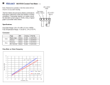
2-2.
Options
The
table
below
should
be
used
to
determine
the
options
that
can
be
used
together
on
a
wire
feeder.
Use
the
column
on
the
left
side
of
the
table
to
choose
the
desired
option
and
follow
the
line
across
to
see
which
options
are
compatible.
Desired
Option
Burn-
back
Control
4-in-i
Control
Digital
Meter(s)
Tach
Feed-
back
Digital
Voltage
Control
Voltage
Control
Run-In
Control
Digital
Dual
Scheduie
Dual
Schedule
Control
Remote
Pendant
Control
Cord
#137
552
(For
RCSP-45)
Burnback
Control
No
Yes
Yes
Yes Yes Yes Yes Yes Yes
4-In-i
Control
(In-
ciudes
prof
low/post
flow,
spotlburnback,
and
trigger
hold
con
trol)
No
Yes
Yes
Yes
Yes
Yes
Yes
Yes
Yes
Digital
Meter(s)/Tach
Feedback
(one
ortwo
meter
option)
Yes Yes
Yes
Yes
Yes Yes
No
Yes
Yes
Digital
Voltage
Control
(DVC)
Yes
Yes
Reqd
No
Yes Yes
No
Yes
Yes
Voltage
Control
Yes
Yes Yes
No
Yes
No
No
No
Yes
Run-in
Control
(Option
interface
Required)
Yes Yes
Yes
Yes
Yes
Yes
Yes Yes
Yes
Digital
Dual
Schedule
(Option
Interface
Re-
quired)
Yes
Yes
Reqd Reqd
No
Yes
No No No
Dual
Schedule
Control
(Option
Interface
Re-
quired)
Yes
Yes
No
No
No
Yes
No
No
No
Remote
Pendant
Con
trol
(Option
Interface
Required)
Yes
Yes
Yes
Yes
No
Yes
No No
No
Cord
#137
552
(For
RCSP-45)
(Option
In-
terface
Required)
Yes
Yes Yes
Yes
Yes Yes
No
No
No
OM-i
582
Page
2

3-1.
Site
Selection
SECTION
3-INSTALLATION
a
WARNING
t_*
I
WARNING:
FALLING
WIRE
FEEDER
can
cause
serious
personal
injury
and
equipment
damage.
Do
not
put
wire
feeder
where
it
will
tip
or
fall.
Put
all
four
rubber
feet
solidly
on
a
flat
surface.
CYLINDERS
can
explode
If
damaged.
Keep
cylinders
away
from
welding
and
other
electrical
circuits.
Never
touch
cylinder
with
welding
electrode.
Always
secure
cylinder
to
running
gear,
wall,
or
other
stationary
support.
ELECTRIC
SHOCK
can
kIll.
Do
not
touch
live
electrical
parts.
The
welding
wire,
drive
rolls,
drive
assembly,
and
all
metal
paris
touching
the
welding
wire
are
electrically
live
when
welding
or
feeding
wire
using
gun
trigger.
wfwam7.1
9/91
Do
not
put
feeder
where
welding
wire
hits
cylinder.
5
1
Wire
Feeder
2
Lifting
Eye
3
Rubber
Feet
4
Installation
Slots
When
installing
wire
feeder
over
a
lifting
eye
on
a
welding
power
source,
select
the
slot
that
will
al
low
all
four
rubber
feet
on
base
of
feeder
to
sit
securely
on
top
of
welding
power
source.
5
Wire
Spool/Reel
6
Gas
Cylinder
(Customer
Supplied)
7
Welding
Power
Source
Position
wire
feeder
on
welding
power
source
so
that
welding
wire,
or
wire
spool/reel,
does
not
touch
gas
cylinder.
3
sT152
586
/
ST-152
568
Figure
3-1.
Installing
Wire
Feeder
Over
A
Lifting
Eye
OM-1582
Page
3

3-2.
Equipment
Connection
Diagrams
£~
WARNING
CYLINDERS
can
explode
if
damaged.
Keep
cylinders
away
from
welding
and
other
electrical
circuits.
Never
touch
cylinder
with
welding
electrode.
Always
secure
cylinder
to
running
gear,
wall,
or
other
stationary
support.
HOT
SURFACES
can
burn
skin.
Allow
gun
to
cool
before
touching.
ELECTRIC
SHOCK
can
kill.
Do
not
touch
live
electrical
parts.
Tum
Off
wire
feeder
and
welding
power
source,
and
disconnect
input
power
before
making
connections.
Stop
engine
on
welding
generator.
The
welding
wire,
drive
rolls,
drive
assembly,
and
all
metal
parts
touching
the
welding
wire
are
electrically
live
when
welding
or
feeding
wire
using
gun
trigger.
Have
only
qualified
persons
install
this
unit.
Figure
3-2.
Connections
With
A
Constant
Voltage
(CV)
Or
Constant
Voltage/Constant
Current
(CV/CC)
Welding
Power
Source
Having
A
14-Socket
Receptacle
And
24
VAC
Supply
NOTE
~
If
using
wire
feeder
with
an
engine-driven
power
source,
place
engine
control
____________________
switch
in
Run
(high
speed)
position.
Some
wire
feeders
may
work
with
switch
in
Run/Idle
position.
wfwamg.1
2193
1
CV
Or
CC/CV
Welding
Power
Source
Supplying
24
VAC
To
Feeder
2
14-Pin
Plug
PLG1O
And
Inter
connecting
Cord
3
Positive
(+)
Weld
Cable
4
Negative
()
Weld
Cable
5
Workpiece
6
Voltage
Sensing
Lead
7
Gun
8
Wire
Feeder
9
Y
Adapter
Gas
Hose
10
Gas
Cylinder
ST-152
616
OM-1582
Page
4

CV
Welding
Power
Source
2
PSA-2
Interconnecting
Cord
(Supplied
With
PSA-2
Con
trol)
Positive
(+)
Weld
Cable
Negative
()
Weld
Cable
Workpiece
Voltage
Sensing
Lead
Gun
Figure
3-3.
Connections
With
A
Constant
Voltage
(CV)
Welding
Power
Source
Having
Only
115
VAC
Available
3
4
5
6
7
8
9
Wire
Feeder
14-Pin
Plug
PLG1O
And
Inter
connecting
Cord.
10
PSA-2
Control
(Optional)
11
V
Adapter
Gas
Hose
12
Gas
Cylinder
2
4
5-
8
9
11
ST-152
320
OM-1582
Page
5

3-3.
Wire
Guide
And
Drive
Roll
Installation
4~
WARNING
CYLINDERS
can
explode
if
damaged.
Keep
cylinders
away
from
welding
and
other
electrical
circuits.
Never
touch
cylinder
with
welding
electrode.
Always
secure
cylinder
to
running
gear,
wall,
or
other
stationary
support.
HOT
SURFACES
can
burn
skin.
Allow
gun
to
cool
before
touching.
ELECTRIC
SHOCK
can
kill.
Do
not
touch
live
electrical
parts.
Tum
Off
wire
feederand
welding
powersource,
and
disconnect
input
power
before
making
connections.
Stop
engine
on
welding
generator.
The
welding
wire,
drive
rolls,
drive
assembly,
and
all
metal
parts
touching
the
welding
wire
are
electrically
live
when
welding
or
feeding
wire
using
gun
trigger.
Have
only
qualified
persons
install
this
unit.
wfwamg.1
2/93
A.
Wire
Guide
Installation
Figure
3-4.
Wire
Guide
Installation
When
changing
wire
size
or
type,
check
guide
size
(see
Table
7-2).
1
Drive
Rolls
Remove
drive
rolls
before
installing
wire
guides
(see
Figure
3-5).
2
Wire
Guide
Securing
Screws
Loosen
wire
guide
screws.
3
Antiwear
Guide
4
Inlet
Wire
Guide
Install
inlet
wire
guide
into
antiwear
guide.
Install
inlet
guide
so
wire
guide
screw
is
centered
in
groove
in
guide.
5
Intermediate
Wire
Guide
Insert
intermediate
guide
until
flange
on
guide
rests
against
cast
ing,
and
secure
with
guide
screw.
Install
drive
rolls
(see
Figure
3-5).
Repeat
procedure
for
opposite
side
of
wire
feeder.
)
5/64
in
ST-153
125-B
/
ST.137
317-D
Tools
Needed:
1
OM-1
582
Page
6

B.
Drive
Roll
Installation
Figure
3-5.
Drive
Roll
Installation
(Four-Drive
Roll
Model
Shown)
3-4.
Welding
Gun
Connections
£~
WARNING
ELECTRIC
SHOCK
can
kill.
Do
not
touch
live
electrical
parts.
Turn
Off
wire
feeder
and
welding
power
source,
and
disconnect
input
power
before
Inspecting
or
installing.
Stop
engine
on
welding
generator.
wfwarnl.1
2/93
Figure
3-6.
Gun
And
Trigger
Lead
Connections
When
changing
wire
size
or
type,
check
drive
roll
size
(see
Table
7-2).
1
Spring
Shaft
Carrier
Close
spring
shaft
carrier.
2
Drive
Roll
Nut
3
Drive
Roll
Carrier
Turn
nut
one
click
until
lobes
of
nut
line
up
with
lobes
of
drive
roll
carri
er.
Open
spring
shaft
carrier.
4
Drive
Roll
Slide
drive
roll
onto
drive
roll
carri
er.
Turn
nut
one
click.
Repeat
procedure
for
top
drive
roll.
5
Drive
Assembly
Cover
Close
cover.
Repeat
procedure
for
opposite
side
of
wire
feeder.
ST-137
377~D
4
1
GunSecunngKnob
2
Gun
Block
3
Gun
End
Loosen
gun
securing
knob.
Insert
end
into
block.
Position
as
close
as
possible
to
drive
rolls
without
touch
ing.
Tighten
knob.
4
Gun
Trigger
Plug
Insert
plug
into
receptacle,
and
tight
en
threaded
collar.
5
Gun
Trigger
Receptacle
6
Drive
Assembly
Cover
Close
cover.
Repeat
procedure
for
welding
gun
on
opposite
side
of
wire
feeder.
Ref.
$1149652/
Ref.
ST-152
466
OM-1
562
Page
7

3-5.
Motor
Start
Control
ELECTRIC
SHOCK
can
kill.
Do
not
touch
live
electrical
parts.
TurnOffwirefeederandweldingpowersource,
and
disconnect
input
power
before
inspecting
or
installing.
Stop
engine
on
welding
generator.
STATIC
ELECTRICITY
can
damage
parts
on
circuit
boards.
Put
on
grounded
wrist
strap
BEFORE
handling
boards
or
parts.
wfwaml.r
2/93
Figure
3-7.
Motor
Start
Control
On
Motor
Control
Board
PCi
To
change
wire
feed
starting
speed,
proceed
as
follows:
Turn
Off
wire
feeder
and
welding
power
source.
Remove
wrapper.
Front
panel
shown
open
for
illustra
tion
purposes.
2
Left
Side
Inner
Control
Panel
It
may
be
necessary
to
remove
panel
to
access
Motor
Start
Con
trol.
Remove
panel
only
as
far
as
required
if
options
are
attached
to
panel.
3
Motor
Board
PCi
4
Motor
Start
Control
Poten
tiometer
R70
Turn
potentiometerclockwiseto
in
crease
time
it
takes
the
motor
to
ramp
up
to
speed.
Remove
protec
tive
white
rubber
cap
before
mak
ing
adjustment.
Adjust
potentiome
ter
R70
using
a
small
nonconduc
tive
screwdriver.
Reinstall
left
side
inner
control
pan
el
if
it
was
removed.
Reinstall
wrapper.
Ref.
ST-143
259-E
/
Ref.
SB-146
862-0
£~
WARNING
1
Front
Panel
Tools
Needed:
c~~zJ=~n
1/4
in
OM-1582
Page
8

3-6.
Dip
Switches
Options
AA
WARNING
ELECTRIC
SHOCK
can
kill.
Do
not
touch
live
electrical
parts.
Turn
Off
wire
feeder
and
welding
power
source,,
disconnect
input
power
before
inspecting
installing.
Stop
engine
on
welding
generator.
STATIC
ELECTRICITY
can
damage
parts
on
circuit
boards.
Put
on
grounded
wrist
strap
BEFORE
handling
boards
or
parts.
wfwamlV
2/93
A.
SpotlTime
DIP
Switch
Si
Change
DIP
switch
position
If
a
dif
ferent
range
of
Spot/Time
Is
de
sired.
1/4
in
Ref.
ST-143
259-E
/
SA-146
868-A
Figure
3-8.
Spot/Time
DIP
Switch
Si
Turn
Off
wire
feeder
and
welding
power
source.
Remove
wrapper.
1
Front
Panel
Remove
screw
from
upper
left
cor
ner,
and
open
hinged
front
panel
if
necessary.
2
4-In-i
Board
PC3O
3
Spot/Time
D~P
Switch
SI
Place
switch
(on
either
or
both
PC3O
boards)
in
desired
position:
Long
Time
for
0-5
seconds,
and
Short
Time
for
0-2.5
seconds
(see
Figure
4-12
for
control
operation).
Close
and
secure
front
panel,
and
reinstall
wrapper.
1
Tools
Needed:
OM-1582
Page
9

B.
Digital
Meter
Functions
And
Positions
The
Digital
Meter
Board
PC6O
for
the
Two
Meter
Option
is
equipped
with
DIP
switch
S3.
This
switch
is
shipped
from
the
factory
in
the
Off
position,
and
should
not
be
changed.
Change
DIP
switch
positions
if
a
different
mode
of
operation
is
de
sired.
Turn
Off
wire
feeder
and
welding
power
source.
Remove
the
six
(6)
screws
from
front
edge
of
wrapper.
1
Front
Panel
Front
panel
shown
open
for
illustra
tion
purposes.
2
Digital
Meter
Board
PC6O
3
Meter
Functions
DIP
Switch
S2
Place
switch
in
appropriate
posi
tion
for
desired
mode
(see
Figure
4-7
for
meter
operation).
Some
units
have
a
5-position
DIP
switch
which
corresponds
to
the
bottom
five
positions
of
the
9-posi
tion
switch
shown.
Reinstall
wrapper
screws.
Figure
3-9.
Digital
Meter
Functions
DIP
Switch
S2
Ref.
ST-143
259-E
I
Ref.
5-0389-A
/
SA-135
481-K
OM-1
582
Page
10
Or
Standard
Motor
Inches/Minute
Standard
Motor
Meters/Minute
High
Speed
Motor
High
Inches/Minute
Speed
Meters/Minute
I
I
j:
j;
I
I I
I
Ir
~
~
~
I
(D
~
I
I
u
u,
Or
I
I
I~
I
I~
t~)
C~)
c~
cJ
I
N
><.-
><-
><
><-
Or
Voltage
Monitor
><~
><~
><~-
><(D
><~n
><~
><~,
><c~
I
~jT~
~
Means
place
switch
in
this
position.
X
Means
switch
can
be
In
either
position.
~1
Tools
Needed:
c~z=n
1/4
in
/