
USER MANUAL


4
WARRANTY
AvMap warrants their GPS receiver and accessories to be free of defects in material and work-
manship for a period of two years from the date of original purchase. This warranty applies only
to the original purchaser of this product. In the event of a defect, AvMap, at its option, will
repair or replace the product with no charge to the purchaser for parts or labor. The repaired
or replaced product will be warranted for ninety (90) days from the date of return shipment, or
for the balance of the original warranty, whichever is longer.
PURCHASER’S REMEDY - Purchaser’s Exclusive Remedy under this written warranty or any
implied warranty shall be limited to the repair or replacement, at AvMap’s option, of any
defective part of the receiver or accessories which are covered by this warranty. Repairs under
this warranty shall only be made by an authorized AvMap dealer.
PURCHASER’S DUTIES - To obtain warranty service, the purchaser must return the receiver
or accessories post paid, with proof of the date of original purchase and purchaser’s return
address to AvMap, or an authorized AvMap representative. AvMap will not be responsible for
any losses or damage to the product incurred while the product is in transit or is being shipped
for repair. Insurance is recommended.
LIMITATION OF IMPLIED WARRANTIES - Except as set forth above, all other expressed or implied
warranties, including those of fitness for any particular purpose and merchantability, are hereby
disclaimed. Some states do not allow limitations on warranties, so the above limitation may
not apply to you.
EXCLUSIONS - This warranty does not cover the following: Installation, Finishes, Defects resulting
from installation. Any damage due to accident, resulting from inaccurate satellite transmissions.
Inaccurate transmissions can occur due to changes in the position, health, or geometry of a
satellite. Any damage due to shipping, misuse, negligence, tampering or improper use. Servicing
performed or attempted by anyone other than an authorized AvMap representative.
Attenzione! L’esposizione del display ai raggi ultravioletti può accorciare la vita dei
cristalli liquidi usati nel vostro plotter cartografico. Questo limite è dovuto alla tecnologia costruttiva
degli attuali display. Evitare inoltre che il display si surriscaldi per non causare una diminuzione di
contrasto che, in casi estremi, può rendere lo schermo completamente nero. Tale condizione è
comunque reversibile durante il raffreddamento.
Warning! Exposure of display to UV rays may shorten life of the liquid crystals used in
your plotter. This limitation is due to the current technology of the LCD displays. Avoid overheating
which may cause loss of contrast and, in extreme cases, a darkening of the screen. Problems which
occur from overheating are reversible when temperature decreases.
Achtung! Ultraviolette Strahlen können die Lebensdauer vom Flüssigkristalldisplay
verkürzen. Die derzeitige LCD-Technologie bedingt diese verkürzte Lebensdauer.
Überhitzung des Displays durch Sonneneinstrahlung führt zu einem Kontrastverlust und in extremen
Fällen sogar in eine Schwär zung des Bildschirmes. Bei sinkenden Temperaturen normalisiert sich
der Kontrast wieder und die Bildschirminformation wird wieder ablesbar.
Attention! L’exposition de votre écran LCD aux ultra-violets lors de soleil intense
réduira la durée de vie de l’afficheur de votre lecteur. Cette contrainte est liée à la technologie des
écrans LCD. Une augmentation trop importante de température peut obscurer des zones de votre
écran et le rendre ainsi inutilisable (non couvert par la garantie).
Aviso! La exposición de la pantalla a los rayos UV puede acortar la vida del cristal líquido
usado en su ploter. Esta limitación se debe a la tecnología actual de las pantallas LCD. Evitar que
la pantalla se caliente en exceso pues puede causar pérdida de contraste y, en caso extremo, la
pantalla puede quedar totalmente negra. Este problema revierte al enfriarse la pantalla

5
Warning!!!
A measure of knowledge by the user is required for proper and safe use of the chart plotter.
Read the User Manual and the Warranty completely.
Use Good Judgement
This product is an excellent navigation aid, but it does not replace the need for careful
pilotage and good judgement. Never rely solely on one means of naviga-tion.
Use Care to Avoid Inaccuracies
The Global Positioning System (GPS) is operated by the U.S. Government, which is solely
responsible for the accuracy and the maintenance of GPS. Certain conditions can make the
system less accurate.
Accuracy can also be affected by poor satellite geometry.
The accuracy of position fixes is subject to changes in accordance with the Department of
Defense civil GPS user policy and the Federal Radionavigation Plan.
Cleaning Procedure for the Chartplotter Screen
Cleaning of the chartplotter screen is a very important operation and must be done carefully.
Since the surface is covered by a antireflective coating, the procedure for cleaning all the
surfaces can be performed using the following procedure: You need a tissue or lens tissue
and a cleaning spray containing Isopropanol (a normal spray cleaner sold for the PC screen,
for example PolaClear by Polaroid). Fold the tissue or lens tissue into a triangular shape,
moisten the tip and use the index finger behind a corner to move the tissue across the
surface, in overlapping side to side strokes. If the tissue is too wet, a noticeable wet film will
be left in its path and you will need to repeat the process. If too dry, the tissue won’t glide
easily, and may damage the surface.
Copyright 2005 AvMap Italy - All rights reserved
No part of this User Manual may be reproduced or transmitted in any form or by any means,
electronic or mechanical, including photocopying and recording , for any purpose other than the
purchaser’s personal use without the written permission of AvMap.

6

7
TABLE OF CONTENTS
1 IntroductIon
1.1 FEATURES 12
1.1.1 Specifications 12
1.2 BASIC 14
1.3 FLYING START 15
1.3.1 The Moving Map 15
1.3.2 The Main Menu 15
1.3.3 Moving Map Functions 15
1.3.4 Moving Map Icons 16
1.3.5 Course Predictor 16
1.3.6 GoTo 17
1.3.7 Database 17
2 the BasIcs
2.1 THE KEYBOARD 18
2.2 TURNING THE GEOPILOT II ON/OFF 19
2.2.1 Turning On 19
2.2.2 Turning Off 19
2.3 CHANGING BRIGHTNESS & CONTRAST 19
2.4 SELECTING THE LANGUAGE 19
2.5 EXTERNAL CONNECTIONS 20
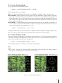
2.5.1 Down Or Up-load Flight Plans & Tracks 20
2.5.1.1 Download/Upload Waypoints 20
2.5.1.2 Download/Upload Flight Plan 20
2.5.1.3 Download Track 20
2.6 SYSTEM SETUP OPTIONS 20
2.7 DATA ENTRY 21
3 the MovIng Maps
3.1 OPERATING MODES 22
3.1.1 Cursor Mode 22
3.1.2 Auto Home (Screen Amplifier) 22
3.1.3 Auto Zoom Mode 22
3.2 DATA WINDOW 23
3.3 AUTOMATIC INFO 23
3.4 CURSOR OR POSITION MODE 23
3.4.1 Airspace Information 23
3.4.2 Full Information 24
3.4.3 Project Radial 24
3.4.4 A - B Function 24
3.4.5 Waypoint Handling 25
3.4.6 Flight Plan 25
3.5 MOVING MAP MENU 26
3.5.1 Viewed Fp 26
3.5.2 Auto Position Mode 27
3.5.3 Data Window mode 27
3.5.4 Setup Data Fields 28
3.5.5 Default Datafields 28
3.5.6 Map Orientation 28

8
3.5.7 Map Presentation Settings 29
3.5.8 Automatic Information 29
3.5.9 Rangerings 29
3.5.10 Vfr, Airspace, Land, Marine And Other Settings 30
3.5.10.1 VFR Settings 30
3.5.10.2 Airspace Settings 30
3.5.10.3 Land Settings 31
3.5.10.4 Marine Settings 31
3.5.10.5 Other Settings 32
3.5.11 Terrains 32
3.5.11.1 Terrain “ON” 32
3.5.11.2 Terrain “OFF” 32
3.6 MAP PRESENTATION MENU 32
3.6.1 Generic 33
3.6.2 TAWS 33
3.6.3 Selective Display Settings 34
3.6.4 POI Settings 35
4 navIgatIon & LocatIon
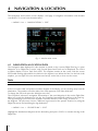
4.1 NAVIGATION & LOCATION DATA 36
4.2 SAVE CURRENT FIX AS USER WAYPOINT 37
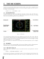
5 the hsI screen
5.1 HSI DESCRIPTION 38
5.2 HSI MENU 38
5.2.1 Add Mark Under Fix 38
5.2.2 Setup Datafields 39
5.2.3 Default Datafields 39
5.2.4 Compass Orientation 39
6 FLIght pLan
6.1 VIEWED FLIGHT PLAN 40
6.2 CREATING A FLIGHT PLAN FROM THE DATABASE 40
6.3 ACTIVATE & DEACTIVATE A FLIGHT PLAN 41
6.4 NAMING A FLIGHT PLAN 42
6.5 CLEAR A FLIGHT PLAN 42
6.6 REVERSE A FLIGHT PLAN 42
6.7 GOTO FLIGHT PLANS 42
6.7.1 GoTo - Database Mode 42
6.7.2 GoTo - Moving Map Mode 43
6.7.3 GoTo - Quick Info 43
6.8 NEAREST SEARCH FOR GOTO FLIGHT PLAN ACTIVATION 43
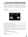
7 the gLoBaL posItIonIng systeM
7.1 GPS PAGE 45
7.2 GPS RECEIVER SPECIFICATIONS 45
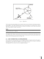
7.3 HOW GPS WORKS 46
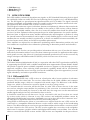
7.3.1 Accuracy 46
7.3.2 WAAS 46
7.3.3 Differential GPS 46
7.3.4 Monitoring & Controlling The GPS 47

9
7.3.5 GPS Information Sources 47
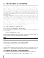
8 WaypoInt & dataBase
8.1 USER WAYPOINTS – MOVING MAP 48
8.1.1 Creating User Waypoints – Moving Map 48
8.1.2 Saving Present Position – Moving Map Methods 48
8.1.3 Editing User Waypoints – Moving Map Methods 48
8.1.4 Deleting User Waypoints – Moving Map Methods 49
8.2 USER WAYPOINTS – DATABASE METHODS 49
8.2.1 Creating User Waypoints – Database Methods 49
8.2.2 Editing User Waypoints – Database Methods 49
8.2.3 Deleting User Waypoints – Database Methods 49
8.3 DATABASE 49
8.3.1 Database Menu 49
8.3.1.1 Selecting Database Search Fields 50
8.3.1.2 Displaying Sunrise and Sunset Information 50
8.3.2 File Manager 50
9 approach data procedures
9.1 APPROACH FROM THE MOVING MAP 52
9.2 APPROACH FROM FLIGHT PLAN DATABASE 52
9.3 SELECT APPROACH FOR GOTO 53
10 caLcuLator
10.1 COUNTDOWN TIMER 54
10.2 ELAPSED TIMER 54
10.3 TRIP COMPUTER 55
10.4 VERTICAL NAVIGATION 55
10.5 WIND CALCULATION 57
10.6 FUEL CONSUMPTION 58
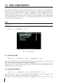
11 the checkLIsts
11.1 ENGINE START 60
11.2 GROUND CHECK 60
11.3 PRE TAKE-OFF 61
11.4 CRUISE IN FLIGHT 61
11.5 LANDING 61
12 sIMuLator
12.1 SIMULATING STRAIGHT MODE 62
12.2 SIMULATING ROUTE MODE 62
12.3 TURNING THE SIMULATOR OFF 63
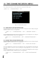
13 the coMMunIcatIon Menu
13.1 WAYPOINTS UPLOAD/DOWNLOADS 64
13.2 FLIGHT PLAN UPLOAD/DOWNLOAD 64
13.3 TRACK DOWNLOAD 65

10
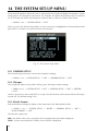
14 the systeM set-up Menu
14.1 GENERAL SET-UP 66
14.1.1 Beeper 66
14.1.2 Scale Format 66
14.1.3 Language 67
14.1.4 Military Frequency 67
14.1.5 Airspaces Level 67
14.1.6 Terrain Legend 67
14.2 FIX SET-UP 67
14.2.1 Fix Source 67
14.2.2 Differential Correction Source 67
14.2.3 Fix Symbol 68
14.2.4 Static Navigation 68
14.2.5 Course Predictor 68
14.2.6 Head Up Response 68
14.3 ALARM SET-UP 68
14.3.1 Arrival Alarm Radius 68
14.3.2 XTE Alarm Range 69
14.3.3 Waypoint Alarm Radius 69
14.3.4 TAWS Alarm 69
14.3.5 Airspace Ahead Alarm 69
14.3.6 Event Log 70
14.3.7 Clear Event Log 70
14.4 TRACK SET-UP 70
14.4.1 Track Display 70
14.4.2 Track Line 70
14.4.3 Track Width 70
14.4.4 Track Color 70
14.4.5 Track Recording Step 70
14.4.6 Clear Track 71
14.4.7 Remaining Track 71
14.5 UNITS SET-UP 71
14.5.1 Distance Unit 71
14.5.2 Speed Units 71
14.5.3 Altitude Unit 71
14.5.4 Depth Unit 72
14.5.5 Fuel Unit 72
14.5.6 Vertical Speed 72
14.5.7 Temperature 72
14.5.8 North Reference 72
14.5.9 Coordinate System 72
14.6 DATE & TIME SET-UP 73
14.6.1 Time Format 73
14.6.2 Local Time Difference 73
14.6.3 Data Format 73
14.7 COLORS SET-UP 73
14.7.1 Data Window Colors 74
14.8 CLEAR USER DATA 74
14.9 CLEAR ALL RADIALS 74
14.10 FACTORY DEFAULTS 74
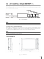
15 operatIng requIreMents
15.1 SECURING THE GEOPILOT II 75

11
15.2 DIMENSIONS 75
15.3 TROUBLESHOOTING 76
15.3.1 Power 76
15.3.2 GPS Fix 76
15.3.3 When Nothing Else Works 76
15.3.4 Customer Support 77
15.4 SYSTEM TEST 77
15.4.1 RAM Menu 78
15.4.2 C-CARD Menu 78
15.4.3 Serial Ports 78
APPENDIX A - TERMS 79
APPENDIX B - MAP DATUM 82
APPENDIX C - ICAO CODES 83
APPENDIX D - C-MAP AV. CARTRIDGE OPTIONS 89
APPENDIX E - C-MAP DATA TRANSFER 90

12
1 INTRODUCTION
If you have not used a GPS Charting System before and intend to use your Geopilot II for
navigating, we suggest that you read this User Manual and make sure you are familiar with its
contents. Throughout this User Manual, the keys are shown in capital letters enclosed between
single inverted commas, for example ‘MENU’. Menu operations are in bold characters listed by
keys sequence with the menu names enclosed between quotes, for example ‘MENU’ 1 sec. +
“SYSTEM SETUP” + ‘ENT’ + “FIX SETUP” + ‘ENT’ means: press and hold down the ‘MENU’ key
for 1 second, using the cursor key selects the System Setup menu, press ‘ENT’, using the cursor key
selects the Fix Setup menu and then press ‘ENT’.
1.1 FEATURES
This electronic charting system integrates the remarkable accuracy of a GPS receiver with a detailed
moving map into a single, easy-to-use, computerized electronic map system. The Geopilot II
contains a built-in base map with coast/shorelines, names of states, major cities, highways, lakes
and rivers.
When the Geopilot II is first opened, please check it for the following contents:
• SD (2 GB) with Aeronautical+Jeppesen Maps (inserted in the slot on the left side of the unit)
• Power cord
• Suction cup mount
• Quick guide
Optional Accessories:
• PC/Data cable
If any parts are missing contact the dealer where you purchased it immediately: additional C-MAP
NT+ Compact Flash (cartography and aeronautical data cards) and mounting hardware options are
available through your local dealer.
For additional information, visit our web site at: www.avmapnavigation.com
1.1.1 Specifications
Main Characteristics
Recordable Individual points
• Waypoints:1000
• Type of User Waypoint Icons:16
Flight Plans
• Flight Plans: 15
• Max Waypoints per Flight Plan: 100
Tracking
• Tracks: 1
• Track Colors: 7
• Points per Track: 5000
• Step by Distance: Auto, 20, 100, 500 Mt, 1Km; 5, 30 Sec, 1 Min

13
Cartographic Functions
• Worldwide Background
• Built-in Continental Cartography
• Coordinates System (DDD MM SS, DDD MM.mm, DDD MM.mmm, UTM, OSGB, MGRS)
• North Reference
• Auto Zoom
• Map Presentation (Aero+Terrestrial, Aeronautical, Marine)
• POI Settings
• Selective and cycled Display
• VFR (Airports, VOR, NDB, Intersections, Vertical Obstructions, Aero Objects Id, Enroute
Communications)
• Airspace (Controlled Areas, Restricted Areas, FIR & UIR, MORA)
• Land (Roads, Road Labels, Railroads, City Names, Rives and Lakes, Cultural Features, Natural
Features, Landmarks, POI Objects)
• Marine (Lights, Chart Boundaries, Bathymetric & Soundings, Bathymetric & Soundings Range,
Depth Area Limit, Navigational Aids, Attention Areas, Tracks & Routes)
• Other Settings (User Points, Objects Overlap, Lat/Lon Grid)
Fix Functions
• DGPS
• WAAS
• Fix Symbol user selectable (Standard, Plane, Helicopter, Car)
• Static Navigation
• Course Predictor
• Map Orientation (Track-up, Course-up, North-up)
• Projected Radial
• A-B measurement
Data Page Options
• Nav/Location
• HSI Page
• Flight Plan
• GPS Page
• About Page
Special Functions
• Automatic Info (Aero+Terrestrial, Aeronautical, Terrestrial, Marine)
• Nearest search
• Direct-To navigation
• Date and Time Format
• Astronomic Data Calculation (Sun/Moon Info)
• Distance Unit selection (KM, NM, SM)
• Speed Unit selection (MPH, KTS, KMH)
• Altitude Unit selection (FT, FL, MT)
• Depth Unit selection (FT, FM, MT)
• Fuel Unit selection (GAL, LIT, LB, KG, BGAL)
• Descent Rate selection (FT/MIN, M/S, DEG)
• Temperature Unit (C/F)
• Alarms handling (Arrival, XTE, Waypoint Alarm Radius, Airspace)
• Database(Airports, VOR, NDB, Intersections, POI objects, User Waypoints, File Manager)
• Calculator (Countdown Timer, Elapsed Timer, Trip Computer, Vertical Navigation, Wind
Calculation, Fuel Consumption)
• Simulation mode (Speed, Heading)
• Checklists (Engine Start, Ground Check, Pre Take-Off, Landing)
• Communications (Waypoints Upload/Download, Flight Plan Upload/Download, Track Upload/

14
Download)
Interface
• Serial I/O port
Physical Characteristics
Size
• Ultra-sleek 100x139.7 x 35.4 cm
Weight
• Under 1lib (390 g)
LCD display
• Color 5” LCD TFT ultra bright, sun viewable
• resolution 320x240 pixels
Power Supply
• 10-35 V (cigarette plug power cable)
• Operating Temperature Range 32°F to 131°F (0°C to 55°C)
Storage Temperature
• -13°F to 158°F (-25°C to 70°C)
Keyboard
• Backlighted, silicon rubber
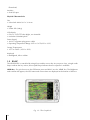
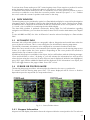
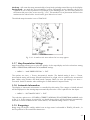
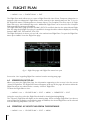
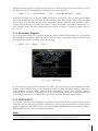
1.2 BASIC
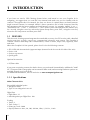
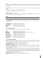
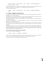
The GEOPILOT2 is controlled by using 6 keys and the cursor key. As you press a key, a single audio
beep confirms the key action; three rapid beeps indicates that no response is available.
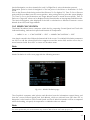
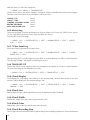
NEAR Key - For quick access to the GPS status press and hold 1 sec the ‘NEAR’ key. The Brightness
and contrast will appear; the GPS status and current time are displayed at the bottom of this box.
Fig. 1.2 - The Geopilot II

15
1.3 FLYING START
These pages provide a very brief overview of several of the Geopilot II’s important features, the
Main Menu, the Moving Map, GoTo flights and locating a Waypoint in the Database. It does not
replace the User Manual, which should be read to get the fullest possible use from your Geopilot
II.
Note
The Geopilot II is an aid to navigation. It does not replace paper charts and good judgement.
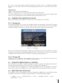
1.3.1 The Moving Map
Before starting, connect the Geopilot II to power and place the antenna with a clear view of the sky.
Turn On the unit pressing ‘NEAR’. Press ‘ENT’ to exit from the Warning page and enter the Moving
Map mode. The Moving Map is the default state displaying the Moving Map screen and the Data
Window. The Data Window contains navigation information boxes (See Chapter 3 for details on
Moving Map mode).
Note: If no Fix is available, red dashed cross is displayed over the map for increased Pilot
Awareness.
To Change the Scale of the Moving Map
Use ‘+’ and ‘-’ to change the map display scale.
To Select Position
Use the cursor key to scroll to the location you want.
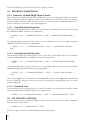
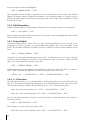
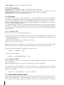
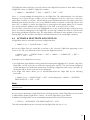
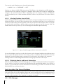
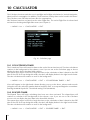
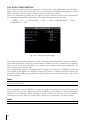
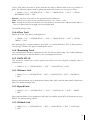
1.3.2 The Main Menu
From Moving Map press ‘MENU’ for 1 second to display the Main Menu:
Fig. 1.3.2 - Main Menu
1.3.3 Moving Map Functions
The Moving Map operates in Auto Home, Auto Zoom, and Cursor Mode. The screen will behave
differently based on the mode of operation selected. The Auto Home mode will allow the user to

16
pan away from his present position to view other parts of the map, and return to present position
automatically when no buttons are pushed for a pre-determined amount of seconds. Auto Zoom
mode will keep your present position, and your destination in the screen at all times. The screen
will automatically zoom in as you get closer. To shut off this function, simply select OFF.
The Cursor Mode (OFF Selected) will allow you to move the map to any position to view data or
details. To return to your present position, just press ‘ESC’ while in moving map.
The control for these functions is found in the Moving Map Menu, under Auto Position Mode.
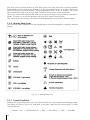
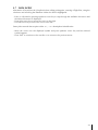
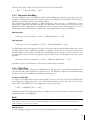
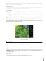
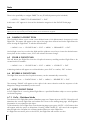
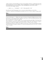
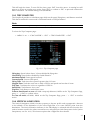
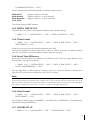
1.3.4 Moving Map Icons
The following icons are displayed on the Moving Map to represent Waypoints, navigation aids and
airports.
Fig. 1.3.4 - Moving Map Icons
1.3.5 Course Predictor
Indicates the projected position at the set time interval if the current speed and heading are kept.
This allows the pilot to correct for wind drift, in real time, right from the moving map. To select
course predictor:
> ‘MENU’ 1 sec. + “SYSTEM SETUP” + ‘ENT’ + “FIX SETUP” + ‘ENT’ + “COURSE

17
PREDICTOR” + ‘ENT’
1.3.6 GoTo
GoTo sets a 1-leg course from the present position to any location or selected Waypoint. To activate
a GoTo Flight Plan move the cursor to the desired location or Waypoint and press ‘GOTO’. The
GoTo menu box will open enabling you to activate the current cursor position or search the
Database for a specific object to fly to. To activate the current cursor position, highlight “CURSOR”
and press ‘ENT’. To activate a GoTo Flight Plan to a specific Database item, select the category and
press ‘ENT’. Select the database item and press ‘GOTO’ again to activate.
To deactivate, press ‘GOTO’ and select “DEACTIVATE”.
1.3.7 Database
The Database function allows the user to access information stored in the data cartridges on
Airports, VOR’s, NDB’s, Intersections and User Waypoints. Searching the Database allows the user
to activate GoTo Flight Plans and locate the item on the map. There are two methods of accessing
the Database information. The first is through the Database function within the Main Menu and the
second is directly from the Moving Map display (see Chapter 3).

18
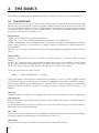
2 THE BASICS
This chapter provides general information about the functions of the keys and entering data.
2.1 THE KEYBOARD
The GeoPilot2 has 7 keys, which access and control features. Some keys perform different tasks
based on the operation mode. A quick key guide is displayed at the bottom of many menus for easy
reference. Below we indicate the keys in capital letters enclosed between single inverted commas,
for example ‘MENU’. When a key, for example ‘MENU’, must be pressed and held down for more
than 1 second it is shown as ‘MENU’ 1 sec.
The Near key
‘NEAR’: press and hold to turn the GeoPilot2 On.
‘NEAR’ 3 sec.: once the GeoPilot has been turned On turns the GeoPilot Off.
‘NEAR’: (immediately release!) Displays a list of the 20 nearest objects, including private airports
which contain runways of at least 500 ft. in lenght, relative to fix position or cursor position if no
fix is available.
‘NEAR’: 1 sec once the GeoPilot2 has been turned On displays the Brightness and the Contrast
Menu.
The GoTo key
Activates a Flight Plan to the cursor position (in Moving Map) or to selected object (in other
modes).
GOTO 1 sec.: allows the user to quickly filter mapping information on the display. There are three
Cycle modes selectable and holding GOTO shifts from one to the other in succession. The default
Cycle is the Cycle 1 that normally activates all features to be visible on the display.
To set user preferences for the Cycle Key:
‘MENU’ + “SELECTIVE DISPLAY” + ‘ENTER’
The Cycles appear in the first three columns and are labeled 1, 2 and 3. In order to adjust at which
Cycle features appear, use the Cursor Control key to highlight an item and hit ‘ENTER’ to remove
the item from appearing. Hit ENTER again to check the item so that it will appear on the display
when that Cycle is activated. Continue to use this procedure to activate features in Cycles 1 - 3 as
desired.
The - key
Shows less detail of a larger area by changing the chart scale and zooming out on the map display.
The cursor key
Moves the cursor on the Moving Map, quickly and accurately. Also scrolls to the desired options
in menu page(s).
If pressed on the center it works as an ‘ENT’ key, it selects the desired option or confirms selection.
Also opens the Cursor/Position Menu.
The + key
Shows more detail of a smaller area by changing the chart scale and zooming in on the map display.
If pressed outside the Moving Map it can be used as an ‘ENT’ key
The Esc key
Rejects an action, closes a window or activates Home or Auto Zoom mode.

19
‘Esc’ 3 sec. on the moving map changes the position of the fix icon: one configuration displays
the fix icon on the 20% central area of the Moving Map and the other on the exact center of the
screen.
The Menu key
‘MENU’: selects the Moving Map Menu.
‘MENU’: press & hold for 1 seconds: opens the Map Presentation Menu
The menu enables the user to select between generic representation mode, three TAWS modes
(auto, low sep and high sep) and two Weather modes (North America only)
2.2 TURNING THE GEOPILOT II ON/OFF
Before powering On the Geopilot II, check for the correct voltage (10-35 Volt DC).
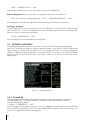
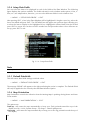
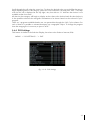
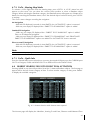
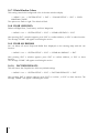
2.2.1 Turning On
Press and hold ‘NEAR’ for 1 second. The Geopilot II emits one rapid beep sound and a Title page
containing information about the Product name, Software version, library version and cartridges
installed is displayed. This data can also be viewed in the “About” page in the “Main Menu”.
Fig. 2.2.1 - Title page
After a few seconds the Warning page is displayed, reminding you that the Geopilot II is an aid to
navigation and should be used with appropriate prudence. The electronic charts are not intended
to substitute for the official charts. Press ‘ENT’ to open the Moving Map screen.
2.2.2 Turning Off
‘NEAR’ 3 sec.: a countdown timer appears on the screen, if you release the key before the
countdown timer reaches zero, the Geopilot II will remain On.
2.3 CHANGING BRIGHTNESS & CONTRAST
Press and hold 1 sec ‘NEAR’ to adjust the brightness and the contrast of the display and keyboard
(do not press and hold the key or the “power-off ” message will be displayed!).
To increase/decrease the brightness use respectively up/down cursor key. Similarly, to increase/
decrease the contrast use left/right cursor key. In addition the Time and the GPS State are shown.
2.4 SELECTING THE LANGUAGE
It is possible to select the language in which the information is displayed (for screen labels, menus
and options, but it does not affect the map information). The default setting is English.
> ‘MENU’ 1 sec. + “SYSTEM SETUP” + ‘ENT’ + “GENERAL SETUP” + ‘ENT’ +
“LANGUAGE” + ‘ENT’

20
Choose the language you want and press ‘ENT’ again to confirm.
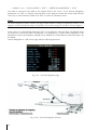
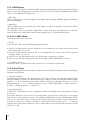
2.5 EXTERNAL CONNECTIONS
2.5.1 Down Or Up-load Flight Plans & Tracks
The Geopilot II can also send and receive Flight Plans from the AvMap Flight Planner or another
device compatible with it through the serial port (the USB port is for factory use only). This requires
an optional data cable that can be purchased from your avionics dealer or AvMap/Navigation for a
proper connection to the device (see following figures).
2.5.1.1 Download/Upload Waypoints
The Download Waypoint function allows you to send the current Waypoints to the serial port using
the NMEA0183 $WPL sentence (see Appendix E):
> ‘MENU’ 1 sec. + “COMMUNICATIONS” + ‘ENT’ + “WAYPOINTS DOWNLOAD” +
‘ENT’
The Upload Waypoint function allows you to receive Waypoints from the serial port using the
NMEA0183 $WPL sentence (see Appendix E):
> ‘MENU’ 1 sec. + “COMMUNICATIONS” + ‘ENT’ + “WAYPOINTS UPLOAD” +
‘ENT’
2.5.1.2 Download/Upload Flight Plan
The Download Flight Plan function allows you to send the current Flight Plans to the serial port
using the NMEA0183 $WPL and $RTE sentences (see Appendix E):
> ‘MENU’ 1 sec. + “COMMUNICATIONS” + ‘ENT’ + “FLIGHT PLAN DOWNLOAD”
+ ‘ENT’
The Upload Flight Plan function allows you to receive Flight Plans from the serial port using the
NMEA0183 $WPL and $RTE sentences (see Appendix E):
> ‘MENU’ 1 sec. + “COMMUNICATIONS” + ‘ENT’ + “FLIGHT PLAN UPLOAD” +
‘ENT’
The received Flight Plan is saved in the current Flight Plan. If the current Flight Plan contains data
the user should be asked to confirm the action (overwriting the existing Flight Plan) or choose
another Flight Plan.
2.5.1.3 Download Track
The Download Track function allows you to send Track data from the serial port using the CMAP
Proprietary NMEA0183 $PCMPT sentence (see Appendix E):
> ‘MENU’ 1 sec. + “COMMUNICATIONS” + ‘ENT’ + “TRACK DOWNLOAD” + ‘ENT’
2.6 SYSTEM SETUP OPTIONS
You may select how the Geopilot II displays primary information (such as how time is displayed)
from the System Setup Menu.
> ‘MENU’ 1 sec. + “SYSTEM SETUP” + ‘ENT’
Refer to Chapter 14 for information about the System Setup Menu.
Page is loading ...
Page is loading ...
Page is loading ...
Page is loading ...
Page is loading ...
Page is loading ...
Page is loading ...
Page is loading ...
Page is loading ...
Page is loading ...
Page is loading ...
Page is loading ...
Page is loading ...
Page is loading ...
Page is loading ...
Page is loading ...
Page is loading ...
Page is loading ...
Page is loading ...
Page is loading ...
Page is loading ...
Page is loading ...
Page is loading ...
Page is loading ...
Page is loading ...
Page is loading ...
Page is loading ...
Page is loading ...
Page is loading ...
Page is loading ...
Page is loading ...
Page is loading ...
Page is loading ...
Page is loading ...
Page is loading ...
Page is loading ...
Page is loading ...
Page is loading ...
Page is loading ...
Page is loading ...
Page is loading ...
Page is loading ...
Page is loading ...
Page is loading ...
Page is loading ...
Page is loading ...
Page is loading ...
Page is loading ...
Page is loading ...
Page is loading ...
Page is loading ...
Page is loading ...
Page is loading ...
Page is loading ...
Page is loading ...
Page is loading ...
Page is loading ...
Page is loading ...
Page is loading ...
Page is loading ...
Page is loading ...
Page is loading ...
Page is loading ...
Page is loading ...
Page is loading ...
Page is loading ...
Page is loading ...
Page is loading ...
Page is loading ...
Page is loading ...
Page is loading ...
Page is loading ...
-
 1
1
-
 2
2
-
 3
3
-
 4
4
-
 5
5
-
 6
6
-
 7
7
-
 8
8
-
 9
9
-
 10
10
-
 11
11
-
 12
12
-
 13
13
-
 14
14
-
 15
15
-
 16
16
-
 17
17
-
 18
18
-
 19
19
-
 20
20
-
 21
21
-
 22
22
-
 23
23
-
 24
24
-
 25
25
-
 26
26
-
 27
27
-
 28
28
-
 29
29
-
 30
30
-
 31
31
-
 32
32
-
 33
33
-
 34
34
-
 35
35
-
 36
36
-
 37
37
-
 38
38
-
 39
39
-
 40
40
-
 41
41
-
 42
42
-
 43
43
-
 44
44
-
 45
45
-
 46
46
-
 47
47
-
 48
48
-
 49
49
-
 50
50
-
 51
51
-
 52
52
-
 53
53
-
 54
54
-
 55
55
-
 56
56
-
 57
57
-
 58
58
-
 59
59
-
 60
60
-
 61
61
-
 62
62
-
 63
63
-
 64
64
-
 65
65
-
 66
66
-
 67
67
-
 68
68
-
 69
69
-
 70
70
-
 71
71
-
 72
72
-
 73
73
-
 74
74
-
 75
75
-
 76
76
-
 77
77
-
 78
78
-
 79
79
-
 80
80
-
 81
81
-
 82
82
-
 83
83
-
 84
84
-
 85
85
-
 86
86
-
 87
87
-
 88
88
-
 89
89
-
 90
90
-
 91
91
-
 92
92


Ask a question and I''ll find the answer in the document
Finding information in a document is now easier with AI
Related papers
Other documents
-
Si-tex Fishplot 10 & 12 User manual
-
Visual Land GPSMAP 296 User manual
-
 II Morrow Inc. Apollo 360 GPS User manual
-
Garmin GPSMAP 295 User manual
-
-
-
Garmin G1000 Nxi - Piper PA-46 Meridian Reference guide
-
Garmin G1000 NXi - Beechcraft King Air C90A/C90GT/C90GTi Reference guide
-
-
