Page is loading ...

CITY MULTI™
Optional Parts for PUHY,PURY-P-YGM/YSGM
1. JOINT
2. HEADER OU-Op-2
3. JOINT KIT CMY-R160-J FOR BC CONTROLLER OU-Op-4
4. HIGH STATIC PRESSURE MOTOR PAC-KBU04MT-F OU-Op-5
OU-Op-3
VI Optional parts for the Outdoor unit R410A Data G2
OUTDOOR UNIT R410A OU - Op - 1

1. JOINT R410A Data G2
OUTDOOR UNIT R410A OU - Op - 2
For gas pipe: For liquid pipe:
ID: Inner Diameter OD: Outer Diameter
Ref.: W901632
mm
CMY-Y102S-G
<Deformed pipe(Accessory)><Deformed pipe(Accessory)>
Piping for CITY MULTITM can be easily done with Joints and headers provided by MITSUBISHI ELECTRIC CORP..
For PUHY-P-YGM/YSGM and PURY-P-YGM, 4 sets of Joints are available. Details for applying the Joint sets are refer-
able to System Design 2-8. or their own Installation Manual.
For gas pipe: For liquid pipe:
ID: Inner Diameter OD: Outer Diameter
Ref.: W901633
mm
CMY-Y102L-G1
<Deformed pipe(Accessory)><Deformed pipe(Accessory)>
For gas pipe: For liquid pipe:
ID: Inner Diameter OD: Outer Diameter
Ref.: W901634
mm
CMY-Y202-G1
<Deformed pipe(Accessory)><Deformed pipe(Accessory)>
For gas pipe: For liquid pipe:
ID: Inner Diameter OD: Outer Diameter
Ref.: W901635
mm
CMY-Y302-G1
<Deformed pipe(Accessory)><Deformed pipe(Accessory)>

2. HEADER R410A Data G2
OUTDOOR UNIT R410A OU - Op - 3
For gas pipe:
For liquid pipe:
Ref.: W901636
mm
CMY-Y104-G
<Deformed pipe(Accessory)>
<Deformed pipe(Accessory)>
Piping for CITY MULTITM can be easily done with Joints and headers provided by MITSUBISHI ELECTRIC CORP..
For PUHY-P-YGM/YSGM and PURY-P-YGM, 3 sets of Headers are available. Details for applying the Header sets are
referable to System Design 2-9. or their own Installation Manual.
For gas pipe:
For liquid pipe:
Ref.: W901637
mm
CMY-Y108-G
<Deformed pipe(Accessory)>
<Deformed pipe(Accessory)>
For gas pipe:
For liquid pipe:
Ref.: W901638
mm
CMY-Y1010-G
<Deformed pipe(Accessory)>
<Deformed pipe(Accessory)>

3. JOINT KIT “CMY-R160-J”FOR BC CONTROLLER R410A Data G2
OUTDOOR UNIT R410A OU - Op - 4
Ref.: WT04350X01_01
This sheet 1pc 1pc 1pc 2pcs 1pc 1pc 8pcs 1pc
(for liquid side)
The Joint kit include following items:
(for gas side) (for gas side) (for liquid side)
1 Instruction 2 Joint pipe 3 Joint pipe 4 Cover 1 5 Cover 2 6 Cover 3 7 Band 8 Reducer
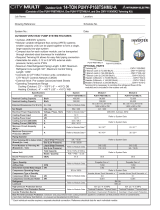
Joint kit "CMY-R160-J" for BC controller is used to combine 2 ports of the BC controller at a PURY-P-YGM system so as to
enable down-stream Indoor capacity above P55 as shown in Fig. 1.
PURY-P-YGM
Joint kit
CMY-R160-J
CMY-Y102S-G
BC controller
Fig.1. CMY-R160-J applying scheme
IU IU IU
IU IU IU IU
Group1
Total Indoor Capacity
<=P54
Group2
Total Indoor Capacity
P54 to P96
Group3
Total Indoor Capacity
P72 or P96
Ref.: WT04350X01_02
Clamping torque 35Nïm
Use two spanners simultaneously for tightening.
Coat the flare contact surface with refrigerating machine oil.
Clamping torque 80Nïm
Use two spanners simultaneously for tightening.
Coat the flare contact surface with refrigerating machine oil.
Piping to indoor unit
(Non-oxidized brazing)
Joint pipe (for liquid side)
2
Joint pipe(for gas side)
3
Flare nut 15.88 (5/8")
Flare nut 9.52 (3/8")
Fig.2. Connecting CMY-R160-J Ref.: WT04350X01_03
2 Joint pipe (for liquid side) 3 Joint pipe (for gas side) mm(in.)
Ref.: W901616
1. Designing CMY-R160-J to a PURY-P-YGM system
The maximum down-stream Indoor capacity for 1 port of BC
controller is P54.When the down-stream Indoor capacity is
above P54, Joint kit CMY-R160-J is needed to combined 2
ports of BC controller to enlarge the capacity, like Group 2 and
3 in Fig. 1.
Maximum 3 Indoor units are allowed to connect to 1 port of BC
controller or 2 combined ports of BC controller using CMY-
R160-J.
When connecting Indoor units to 1 port of BC controller or 2
combined ports of BC controller using CMY-R160-J, CMY-
Y102S-G or CMY-Y104-G is applicable, like Group 1 and 2 in
Fig. 1
Caution: Mixed cooling and heating mode at the same time for
Indoor units connecting to 1 port or 2 combined ports is not
available.
2. Piping at the installation site
The connection of CMY-R160-J to BC controller and pipe leading to Indoor units is referable to Fig. 2. Non-oxidized brazing is
necessary. All piping must be careful to avoid foreign material getting inside.
After piping and air-tight testing, insulation work to the Joint and pipe should be done. Details is available at the Installation Manual.

R410A Data G2
OUTDOOR UNIT R410A OU - Op - 5
4. HIGH STATIC PRESSURE MOTOR PAC-KBU04MT-F
With PAC-KBU04MT-F, the PUHY-P-YGM/YSGM, PURY-P-YGM outdoor unit will gain external 30Pa or 60Pa static
pressure, which makes the outdoor unit exhausting design much easier to coordinate with the building situation.
1. Inside the package of PAC-KBU04MT-F, following items are enclosed together with the installation manual.
2. Installing the high static pressure motor PAC-KBU04MT-F
onto the outdoor unit.
2.1 You may order outdoor unit installed the optional PAC-KBU04MT-F
instead of non-static pressure motor, and set the expected external
static pressure at shipment, or change the motor by yourself at the
field. For the details you need to talk to your provider.
2.2 In the case you change the motor, and set the expected static
pressure at the field. Instruction 2.2a, 2.2b and 2.2c should be
followed.
2.2a. Mounting the motor
A. Remove the screw1, and remove the fan guard, referring to Fig.1.
B. Remove the screw2, and remove the panel 1, referring to Fig.1.
C. Remove the nut, and remove the propeller fan, referring to Fig.2.
D. Remove the connector of the motor, referring to Fig.3.
E. Remove the screw3 of the motor, and exchange the motor,
referring to Fig.4.
F. Connect the motor connectors.
Secure the connectors with a clamp below the motor base not
directly exposed to rainwater, referring to Fig.5.
G. Remove the screw4 from both sides of the side panel and replace
the side panel with the supplied reinforcing plates. referring to
Fig.6. (Other than PUHN type)
H. Put back the propeller fan, fan guard and panel in the reverse
order from A-C.
(Bind the nut tight with the torque of 20 ± 2 N·m.)
I. Attach the supplied label on the unit, referring to Fig.1.
2.2b. Switching for 30Pa or 60Pa static pressure
1 Remove the Panel 2, referring to Fig.1.
2 Remove the control box cover.
3 Set the DIPSW, which is on the front board in the control box,
referring to the figure below.
(For the DIPSW location, refer to the wiring nameplate on the
back of the control box cover).
2.2c. Field work of 2.2a and 2.2b needs working space at the front
and back of the outdoor unit. Enough working space should be
considered for the field work of 2.2a and 2.2b. For example,
upon corrective installation 20mm or the like interval is helpful.
Label
Panel 1
(front)
Screw2
Screw2
Screw1
Fan guard
Fig.1
Panel
(back)
Side
panel
Panel 2
(front)
30Pa
60Pa
30Pa
60Pa
PUHY-P-YGM,YMM,YSM
PURY-P-YGM
DIPSW3-9
ON
ON
DIPSW5-1
ON
OFF
PUHN-P01YGM DIPSW7-1
ON
ON
DIPSW7-4
ON
OFF
Connector
Establish a trap
below the connector.
Secure the motor connector.
The motor connector
must be below the motor base.
Motor
Fig.5Fig.4
Fig.6
Fig.3Fig.2
Nut
Propeller fan
Screw4
Front View
Screw4
Screw3
Fix the wire
by the binder
Screw3
Screw4
Top View
1 Instruction 2 Motor 3 Reinforcing plates 4 Label
11 1
5 Binder
12

R410A Data G2
OUTDOOR UNIT R410A OU - Op - 6
/