Mitsubishi Electronics Heat Pump PUHY-P120YKMU-A (-BS) User manual
- Category
- Split-system air conditioners
- Type
- User manual
This manual is also suitable for

Job Name:
Schedule Reference: Date:
Specications are subject to change without notice.
© 2014 Mitsubishi Electric US, Inc.
Specications System Module 1 Module 2
Unit Type PUHY-P240YSKMU-A (-BS) PUHY-P120YKMU-A (-BS) PUHY-P120YKMU-A (-BS)
Nominal Cooling Capacity (460V) Btu/h 240,000 120,000 120,000
Nominal Heating Capacity (460V) Btu/h 270,000 135,000 135,000
Operating Temperature Range *1
Cooling (Outdoor) *2
Refer to Module Data
23~115° F (-5~46° C) DB
Heating (Outdoor) -4~60° F (-20~15.5° C) WB
External Dimensions (H x W x D)
In.
mm
Refer to Module Data
64-31/32 x 68-29/32 x 29-5/32
1,650 x 1,750 x 740
64-31/32 x 68-29/32 x 29-5/32
1,650 x 1,750 x 740
Net Weight Lbs. / kg 1,452 (658) 726 (329) 726 (329)
External Finish
Refer to Module Data Pre-coated galvanized steel sheet
Electrical Power Requirements Voltage, Phase, Hertz Refer to Module Data** 460V, 3-Phase, 60Hz
Minimum Circuit Ampacity (MCA) A Refer to Module Data** 20 20
Maximum Fuse Size A Refer to Module Data** 25 25
Piping Diameter
From Twinning Kit to First Joint or
Header (Brazed) (In. / mm)
Liquid (High Pressure) 5/8 (15.88) Brazed
Refer to System Data
Gas (Low Pressure) 1-1/8 (28.58) Brazed
Max. Total Refrigerant Line Length Ft. 3,280
Refer to System Data
Max. Refrigerant Line Length
(Between ODU & IDU)
Ft. 541
Max. Control Wiring Length Ft. 1,650
Indoor Unit
Total Capacity
50~130% of outdoor unit
capacity
Refer to System Data
Model / Quantity P06~P96/2~50 Refer to System Data
Sound Pressure Level dB(A) 63 Refer to System Data
Fan
Type x Quantity
Refer to Module Data
Propeller fan x 2 Propeller fan x 2
Airow Rate CFM 11,300 11,300
External Static Pressure In. WG (Pa) Refer to Module Data Selectable; 0, 0.12 or 0.24”WG; factory set to 0”W.G.
Compressor Operating Range 8% to 100% Refer to System Data
Compressor Type x Quantity Refer to Module Data
Inverter-driven Scroll
Hermetic x 1
Inverter-driven Scroll
Hermetic x 1
Refrigerant Refer to Module Data
R410A x 26 lbs + 1 oz
(11.8 kg)
R410A x 26 lbs + 1 oz
(11.8 kg)
Protection Devices
High Pressure
Refer to Module Data
High pressure sensor, High
pressure switch at 4.15 MPa
(601 psi)
High pressure sensor, High
pressure switch at 4.15 MPa
(601 psi)
Inverter Circuit
(Comp. / Fan)
Over-current protection Over-current protection
Fan Motor Thermal switch Thermal switch
AHRI Ratings
(Ducted/Non-Ducted)
EER 12.1 / 12.0
Refer to System DataIEER 18.6 / 18.1
COP 3.55 / 3.53
Blue Fin Anti-corrosion Protection: Cellulose- and polyurethane-resin coating treatment applied to condenser coil that protects it from air contaminants
Standard: ≥1μm thick; Salt Spray Test Method - no unusual rust development to 480 hours.
Sea Coast (BS): ≥1μm thick; Salt Spray Test Method - no unusual rust development to 960 hours.
UNIT OPTION
□ Standard Model….…...…….......…………….PUHY-P240YSKMU-A
□ Sea Coast (BS) Model…….....………….PUHY-P240YSKMU-A-BS
OUTDOOR VRF HEAT PUMP SYSTEM FEATURES
• INVERTER-driven compressor
• Air-source, heat pump system
• Long line lengths - for details see Engineering Manual
• Connects to CITY MULTI indoor units
• Controlled via CITY MULTI Controls Network
Outdoor Unit: 20-TON PUHY-P240YSKMU-A (-BS)
(Consists of Two PUHY-P120YKMU-A (-BS) and One CMY-Y100CBK3 Twinning Kit)
NOTES:
*1. Harsh weather environments may demand performance enhancing equipment.
Ask your Mitsubishi Electric representative for more details about your region.
*2. For details on extended cooling operation range down to -10° F DB, see Low Ambient Kit Submittal.
** Each individual module requires a separate electrical connection.
Refer to electrical data for each individual module.
OPTIONAL PARTS
□ Twinning Kit (required)..............................................… CMY-Y100CBK3
□ Joint Kit.............................…for details see Pipe Accesories Submittal
□ Header Kit.........................…for details see Pipe Accesories Submittal
□ Low Ambient Kit ...............…..for details see Low Ambient Kit Submittal
□ Snow/Hail Guards Kit......…for details see Snow/Hail Guards Kit Submittal

Specications are subject to change without notice.
© 2014 Mitsubishi Electric US, Inc.
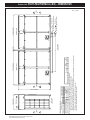
Outdoor Unit: PUHY-P240YSKMU-A (-BS) – DIMENSIONS
ø28.58(1-1/8)
ø15.88(5/8)
CMY-Y100CBK3
PUHY-P120YKMU-A(-BS)
PUHY-P120YKMU-A(-BS)
PUHY-P240YSKMU-A(-BS)
b
a
Gas
Liquid
Outdoor unit 2
Outdoor unit 1
Indoor unit~Twinning pipe
Outdoor Twinning Kit(optional parts)
Component unit name
Package unit name
Twinning pipe connection size
Note 1.Connect the pipes as shown in the figure above. Refer to the table above for the pipe size.
2.Twinning pipes should not be tilted more than 15 degrees from the horizontal plane.
Be sure to see the Installation Manual for details of Twinning pipe installation.
3.The pipe section before the Twinning pipe (sections "a" and "b" in the figure) must have at least 500mm(19-11/16) of straight section
(*including the straight pipe that is supplied with the Twinning pipe).
4.Only use the Twinning pipe by Mitsubishi (optional parts).
d or fc or e
Gas
Liquid
P120
Unit model
Twinning pipe~Outdoor unit
Discharge air
Outdoor unit 2
To indoor unit
Gas Twinning pipe<optional parts>
Liquid Twinning pipe<optional parts>
To indoor unit
Left view
Front view
Intake
air
Intake
air
Intake
air
Outdoor unit 1
ø28.58(1-1/8)ø12.7(1/2)
a
b
f
e
c
d
1650(64-31/32)
1750(68-29/32) 30(1-3/16) 1750(68-29/32)
740(29-5/32)
PUHY-P240YSKMU-A(-BS)
Unit : mm(in.)

Specications are subject to change without notice.
© 2014 Mitsubishi Electric US, Inc.
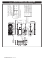
Modules 1 & 2: PUHY-P120YKMU-A (-BS) – DIMENSIONS
(5-17/32) (3-1/16)
(5-29/32) (3-23/32)
(2-1/16)
(1-11/32)
(1-3/8)
(7/8)
(2-15/32)
(1-3/4)
(2-9/16)
(1/2)
(1/2)
(1-1/8)
(1-1/8)
(3/8)
(1/2)
Fan box
ø12.7 Brazed
ø12.7
ø28.58 Brazed
ø28.58
ø9.52 Brazed
Note1.Please refer to the engineering manual for information
regarding necessary spacing around the unit and
foundation work. Outdoor unit must be mounted at least
12" off the ground or 12" above the highest average snow
depth, whichever is greater.
2.At brazing of pipes, wrap the refrigerant service valve
with wet cloth and keep the temperature of
refrigerant service valve under 120°C(248°F).
Refrigerant pipe Service valve
Diameter
Model
Connecting pipe specifications
(ø12.7 Brazed)
PUHY-P144YKMU
PUHY-P120YKMU
Gas GasLiquidLiquid
(26-13/16)
(3-5/32)
(3-5/32)
(2-25/32)
(11-15/16)
(4-25/32)
(5-23/32)
(3-5/16)
(1-3/16)
(1-3/16)
(3-23/32)
(5-31/32)
(7-23/32)
(8-9/16)
(3-17/32) (3-1/16)
(23-5/8)
(25/32)
(25/32)
(13/16) (13/16)
(2-1/4)
(2-1/4)
2
1
4
7
3
2X2-80(3-5/32)X35(1-13/32) Oval hole
<Sling hole>
5
6
Discharge air
Intake
air
Intake
air
Transformer box
Service
panel
Intake
air
2X3-14(9/16)X20(13/16) Oval hole
(Mounting pitch)
(Mounting pitch)
(Mounting pitch)
Control box
Refrigerant service valve
<liquid>
Refrigerant service valve
<gas>
Service panel
2X7-ø4.6(3/16) Hole
(Make hole at the plastic fan guard
for snow hood attachment)
<Snow hood attachment hole>
Refrigerant service
valve <gas>
Refrigerant service
valve <liquid>
(6-25/32)
(8-25/32)
ø65 Knockout hole
ø34 Knockout hole
For transmission cables
ø52 Knockout hole
For pipes
Bottom through hole
150 × 94 Knockout hole
140 × 77 Knockout hole
Front through hole
NO.
Usage
For wires
Front through hole
Front through hole
Bottom through hole
Bottom through hole
Front through hole
ø62.7 or ø34.5 Knockout hole
ø43.7 or ø22.2 Knockout hole
Specifications
*1 Expand the on-site piping and connect to the refrigerant service valve piping.
*2 Use the pipe joint(field supply) and connect to the refrigerant service valve piping.
*3 Indicates dimensions and connection specifications in the case the unit is
used in combination with other outdoor units.
*4 Furthest piping length (OU from IU) 40m(131ft)
*1 *3 *4
*2
*1
*2
58(2-5/16)
75(2-31/32)
541(21-5/16)
217
172
196
151
121
303
1347(53-1/16)
1650(64-31/32)
1750(68-29/32)
19.5
831(32-23/32)
831(32-23/32)
19.5
60070
(740)(29-5/32)
29.529.5
562(22-5/32)
740(29-5/32)
7789
80
795(31-5/16)
795(31-5/16)
80
681
140(5-17/32)
49(1-15/16)
54(2-5/32)
57
20
586(23-3/32)
57
20
223
145
590(23-1/4)
83(3-9/32)
150(5-29/32)
561(22-3/32)
516(20-11/32)
8494
Front view
Top view
Left side view
Bottom view
PUHY-P120,144YKMU-A(-BS)
Unit : mm(in.)
1
2
3
4
5
6
7
>
=

1340 Satellite Boulevard
Suwanee, GA 30024
Toll Free: 800-433-4822
www.mehvac.com
Specications are subject to change without notice.
© 2014 Mitsubishi Electric US, Inc.
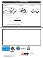
Twinning Kit: CMY-Y100CBK3
1-15/16"
(2 pcs.)
(2 pcs.)
3-7/8"
9-1/2"
7-7/32"
3-9/32"
19-29/32"
13-15/32"
23-5/32"
6-5/16"
2-15/32"
1-15/16"
2-15/32"
Distributer
Distributer
Pipe cover
(Dot-dashed
part)
1/2"
1/2"
1/2"
1/2"
Local brazing
Note 2
5/8"
5/8"
1-1/8"
Note 2
1"
7/8"
1"
7/8"
Pipe cover
(Dot-dashed
part)
Local brazing
1-1/8"
(2 pcs.)
7/8"
3/4"
1/2"
5/8"
1/2"
3/8"
1-1/8"
7/8"
For Gas pipe: For Liquid pipe:
ID: Inner Diameter OD: Outer Diameter
Ref.: CMY_Y100VBK2_EXD_EUDB_SI
in.
CMY-Y100CBK3
<Reducer(Accessory)>
Notes:
The angle of the branch pipe for hign pressure is within against the horizontal plane.
2. Use the attached pipe to braze the port-opening of the distributer.
3. Pipe diameter is indicated by inside diameter.
4. Only use the Twinning pipe by Mitsubishi (optional parts) .
Note 1. Reference the attitude angle of the branch pipe below the fig.
Distributer
15
15
FORM# PUHY-P240YSKMU-A (-BS) - 201407
-
 1
1
-
 2
2
-
 3
3
-
 4
4


Mitsubishi Electronics Heat Pump PUHY-P120YKMU-A (-BS) User manual
- Category
- Split-system air conditioners
- Type
- User manual
- This manual is also suitable for
Ask a question and I''ll find the answer in the document
Finding information in a document is now easier with AI
Related papers
-
 Mitsubishi Electronics PUHY-P96THMU-A User manual
-
 Mitsubishi Electronics Marine Battery H2iSD-1 User manual
-
Mitsubishi Electric PURY-HP192T User manual
-
-
Mitsubishi 250 YHA-A User manual
-
Mitsubishi Electric CITY MULTI PKFY-PVAM-A User manual
-
 Mitsubishi Electronics Fan PAR-30MAAU User manual
-
 Mitsubishi Electronics TG-2000A User manual


Other documents
-
-
-
Continental Automotive Systems LHJ010 User manual
-
-
-
Mitsumi electronic CMY-R100VBK User manual
-
-
Intertherm B6BX Installation guide
-
York GM9S*DH User manual
-
Westinghouse B6BM Series Installation guide