Page is loading ...

ECLIPSE2 IPCommander User
Eclipse2
IP Commander Software
User Manual
P
ublication Reference
23 November 2011
ECLIPSE2 IPCommander User
Manual
Eclipse2
IP Commander Software
User Manual
ublication Reference
– 0308920019
23 November 2011
1
IP Commander Software

ECLIPSE2 IPCommander User Manual
2
Disclaimer
Due to our policy of continuous improvement of our products and services, technical
specifications and claims that were correct at time going to print maybe subject to
variation without notice. RF Technology has endeavoured to ensure that the
information in this document is correct, but does not accept liability due to
typographical, omissions or other errors or subsequent modifications of the product.
Copyright
All information contained in this manual is the property of RF Technology Pty Ltd.
All rights are reserved. This manual may not, in whole or in part, be copied,
photocopied, reproduced, translated, stored, or reduced in any manner without
prior written permission.
All trade names referenced are the trademarks or registered trademarks of the
respective manufacturers.
RF Technology Pty Limited
Unit 46 / 7 Sefton Road
Thornleigh NSW 2120
Sydney Australia
Phone +61 2 9484 1022
Fax +61 2 9484 1288
Web www.rftechnology.com.au

ECLIPSE2 IPCommander User Manual
3
Contents
Contents ............................................................................................................................................ 3
1. Introduction ................................................................................................................................... 6
2. Getting Started .............................................................................................................................. 6
2.1. Connection ............................................................................................................................. 6
2.2. Default Login .......................................................................................................................... 8
2.3. Changing Admin Password ..................................................................................................... 8
2.4. Auto Login .............................................................................................................................. 9
3. Base Station Menu ...................................................................................................................... 10
3.1. Adding a Base Station Connection ....................................................................................... 10
3.2. Connecting to a Base Station ............................................................................................... 11
4. Admin Menu ................................................................................................................................ 12
4.1. Users ..................................................................................................................................... 12
4.2. Base Station Software .......................................................................................................... 13
4.3. Backup and Restore .............................................................................................................. 13
4.3.1. Backup ........................................................................................................................... 14
4.3.2. Restore .......................................................................................................................... 14
4.4. Check for Update .................................................................................................................. 14
4.5. Auto Check Updates ............................................................................................................. 14
4.6. Slow Connection ................................................................................................................... 15
4.7. Play Alarm Audio .................................................................................................................. 15
4.8. Reboot Base Station ............................................................................................................. 15
5. Overview ..................................................................................................................................... 16
5.1. Operational Channel ............................................................................................................ 17
5.2. Networking ........................................................................................................................... 17
5.3. Logging (Syslog) .................................................................................................................... 18
5.4. Versions ................................................................................................................................ 18
5.5. Exciter Transmit Power ........................................................................................................ 18
5.6. Reciter Temperature ............................................................................................................ 18
5.7. RX Path ................................................................................................................................. 18
5.8. RSSI ....................................................................................................................................... 19
5.9. C/N ........................................................................................................................................ 19
5.10. Channel Bandwidth ............................................................................................................ 19
5.11. RX P25 NAC ......................................................................................................................... 19
5.12. RX P25 BER ......................................................................................................................... 19

ECLIPSE2 IPCommander User Manual
4
5.12.1. RX VCO ......................................................................................................................... 19
5.13. TX Path ............................................................................................................................... 19
5.14. Forward Power ................................................................................................................... 19
5.15. Reverse Power .................................................................................................................... 19
5.16. Maximum Deviation ........................................................................................................... 20
5.17. TX VCO ................................................................................................................................ 20
5.18. TX P25 NAC ......................................................................................................................... 20
5.19. Voting ................................................................................................................................. 20
6. Signals .......................................................................................................................................... 22
6.1. Using the Signal Map ............................................................................................................ 22
6.2. Function Blocks..................................................................................................................... 24
6.2.1. FM Demodulator ........................................................................................................... 24
6.2.2. FM Modulator ............................................................................................................... 24
6.2.3. Tone Decoder ................................................................................................................ 25
6.2.4. Tone Encoder................................................................................................................. 25
6.2.5. De-Emphasis .................................................................................................................. 25
6.2.6. Pre-Emphasis ................................................................................................................. 26
6.2.7. Line Input ....................................................................................................................... 26
6.2.8. Line Ouput ..................................................................................................................... 26
6.2.9. Gain ............................................................................................................................... 26
6.2.10. Phase Invert ................................................................................................................. 27
6.2.11. Speaker ........................................................................................................................ 27
6.2.12. Microphone ................................................................................................................. 27
6.2.13. Voice Reporting ........................................................................................................... 27
6.2.14. Tone Generator ........................................................................................................... 28
6.2.15. Signal Mix .................................................................................................................... 28
6.2.16. Priority ......................................................................................................................... 28
6.2.17. Notch Filter .................................................................................................................. 28
6.2.18. High Pass Filter ............................................................................................................ 28
6.2.19. Low Pass Filter (LPF) .................................................................................................... 29
6.2.20. Pass Filter (BPF) ........................................................................................................... 29
6.2.21. Band Stop Filter (BSF) .................................................................................................. 29
6.2.22. APCO P25 Demodulator .............................................................................................. 29
6.2.23. APCO P25 Modulator .................................................................................................. 29
6.2.24. Talkgroup Out (VoIP/RoIP) .......................................................................................... 30

ECLIPSE2 IPCommander User Manual
5
6.2.25. Talkgroup IN (VoIP/RoIP) ............................................................................................. 30
6.2.26. Multi-Tone Decoder .................................................................................................... 31
6.2.27. Multi-Tone Encoder ..................................................................................................... 31
6.2.28. Continuous Wave Identification .................................................................................. 32
7. Channels ...................................................................................................................................... 35
7.1. Overview .............................................................................................................................. 36
7.2. FM & P25 RX Profile ............................................................................................................. 36
7.3. FM & P25 TX Profile .............................................................................................................. 36
7.4. RX Subaudio .......................................................................................................................... 37
7.5. TX Subaudio .......................................................................................................................... 37
7.6. RX Mute/RSSI........................................................................................................................ 37
7.7. RX P25 ................................................................................................................................... 37
7.8. TX P25 ................................................................................................................................... 37
7.9. TX P25 ................................................................................................................................... 38
7.10. TX CWID .............................................................................................................................. 38
7.11. Trace ................................................................................................................................... 38
8. Calibration ................................................................................................................................... 40
8.1. Codec calibration .................................................................................................................. 40
8.2. Output power calibration ..................................................................................................... 40
8.3. RSSI calibration ..................................................................................................................... 41
9. SNMP ........................................................................................................................................... 42

ECLIPSE2 IPCommander User Manual
6
1. Introduction
The Eclipse2 series product range is a radio platform that provides an
array of features and applications.
The IP Commander software is used to monitor and configure a range of parameters,
within the Eclipse2 Transceiver Modules, via the local USB port or remotely using the
Internet Protocol over Ethernet.
IP Commander is a platform independent application, written in Java®, and will run on
many operating systems, including all versions of Microsoft® Windows, Apple® MAC OS
and Linux.
IP Commander can additionally calibrate and update the Eclipse2 Transceiver Module
firmware via USB or remotely over Ethernet.
2. Getting Started
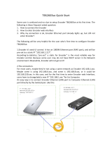
2.1. Connection
To physically connect the computer running IP Commander to the Eclipse2
Transceiver Module, use the front mounted USB connector or the rear mounted
Ethernet socket.
A standard “Type A” USB cable or RJ45 terminated Ethernet cable is required to
connect to the Eclipse2 Transceiver module.
Note that the USB connection is not supported under Microsoft Vista®.
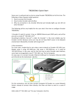
The Eclipse2 has a preconfigured IP address of 192.168.1.201, however customers can
specify their own IP addresses at time of order.
Ensure that the computer, on which IP commander is running, is on the same IP
network as the Transceiver Module. The network mask will be 192.168.1.XXX when
using the Transceiver Module’s default IP address.
If you are unable to connect via the Ethernet connection or if the IP Address is unknown,
you can still connect by using the front panel mounted USB port. The IP Address can be
reset to a value of 192.168.1.201 by simultaneously pressing, and holding, the front
panel speaker and microphones PTT buttons, for five seconds.
NOTE: The IP Address reset sequence will not work if the front panel is
disabled.

ECLIPSE2 IPCommander User
Manual
Figure
1
Base station front an
Manual
Base station front an
d rear views
7

ECLIPSE2 IPCommander User Manual
8
2.2. Default Login
Start IP Commander by clicking on the desktop icon and log in using the
following user name and password and click “OK”
Default User Name: admin
Default Password: rft
NOTE: The logon screen will not
be displayed if “Auto
Logon” is enabled.
NOTE: The user name and
password are case
sensitive.
2.3. Changing Admin Password
To change the administrator password:
1. Select “Admin” from the main menu bar.
2. Select “Users”.
3. Select “admin” from the list and click “Edit”.
4. Enter and confirm your new password and click “OK”
Figure
2
Login screen
Figure
3
Changing Administrator Password

ECLIPSE2 IPCommander User Manual
9
2.4. Auto Login
IP Commander can be setup to auto login, without requiring a username and password.
To enable Auto Login select “Admin” from the toolbar and click “Auto Login”
NOTE: Auto Login is enabled by default. If you upgrade IP Commander, you will
need to turn Auto Login off after the upgrade is complete.
Figure
4
Auto Login

ECLIPSE2 IPCommander User Manual
10
3. Base Station Menu
The Base Station Menu stores a list of base stations, to which IP Commander may be
connected.
3.1. Adding a Base Station Connection
To configure a base station connection, select from the main toolbar “File” then
select “Base Stations”
There are two default entries in the table:
• Eclipse2 default IP Address 192.168.1.201
• Local Base Station using the USB Port
Any entry can be added or removed from the list except for the Local USB Port.
NOTE: The USB Port is always present and cannot be removed.
To add a base station to the connection list, click “Add” and then enter a station
name, a description and the valid IP address of the base station.
An existing entry can also be edited or removed from the list.
Figure 5 Adding a Base Station Configuration

ECLIPSE2 IPCommander User Manual
11
3.2. Connecting to a Base Station
To connect to a base station, double click an entry in the list or highlight an entry
and click “Connect”.
Figure 6 Connecting to a Base Station

ECLIPSE2 IPCommander User Manual
12
4. Admin Menu
The Admin menu allows you to:
• Add or remove users
• Upgrade and rollback Base Station software
• Backup and restore a snapshot of the base station configuration and software.
• Check for Software Updates via the RF Technology website
• Reboot the currently selected Base Station
• Select “Slow Connection <9600bps” speed
• Enable “Alarm Audio”
• Enable “Auto Login”
4.1. Users
The User Configuration menu allows you to add, delete or edit additional users from
the table.
NOTE: There must be at least one entry in the list with the access level set to
Administrator.
Figure
7
User Configuration Menu

ECLIPSE2 IPCommander User Manual
13
4.2. Base Station Software
IP Commander can perform an update or rollback of the base station software.
The Eclipse2 contains two copies of the firmware image, one active and one
inactive. During a software upgrade, the new version is copied to the inactive
memory location, only becoming active after a successful installation. If an
upgrade is interrupted, the original firmware will continue to be active.
The software upgrade is carried out using the local USB port or remotely using the
Ethernet connection.
The firmware files are supplied with a filename in the following format:
• firmware_1_8_0.esw
The filename determines the version number; in the above example, the Version number
is 1.8.0 and the file extension .esw indicates that it is an Eclipse2 software file.
To upload a new firmware file click “Upload” and select the firmware file and click “Apply”.
Once the upload has been completed, the base station will save the current base
station configuration and deploy the new firmware image.
When the new firmware has been deployed, click “OK” to reboot the base station.
During the reboot process, the base station will make the new firmware active and
load the configuration, which was automatically saved from the previous firmware.
A firmware update will take approximately two minutes to complete.
To rollback the firmware back to the previous version, select the inactive version and click
“Apply”.
4.3. Backup and Restore
This process allows the saving and restoration of the base station non-volatile configuration
Figure 8 Base Station Software Upload

ECLIPSE2 IPCommander User Manual
14
data, including the signal map and channel profiles.
4.3.1. Backup
To start the Backup process select “Backup/Restore” from the Admin menu, then type a
filename for the backup file. Click “Save” and the backup process will start.
The backup process will take approximately two minutes to complete.
The backup file will have a default format of “[email protected]”
• Where base_station_name is the text from the networking name field
• xxx.xxx.xxx.xxx is the IP Address of the base station.
• .ebs is the file extension of the backup file.
However, the Backup file can be changed to any name provided the file extension remains
as .ebs
4.3.2. Restore
To start the Restore process select “Backup/Restore” from the Admin menu, then
select a previously saved backup file, click “Open” and the Restore process will start.
The restore process will take approximately two minutes to complete.
4.4. Check for Update
Select “Check for Update” to make IP Commander to immediately check for any software
updates via the internet.
This function is currently not implemented.
4.5. Auto Check Updates
This selection allows IP Commander to check automatically for any software updates via the
internet.
This function is currently not implemented.
Figure
9
Base Station Configuration
Restore

ECLIPSE2 IPCommander User Manual
15
4.6. Slow Connection
This selection adjusts IP Commander’s response time to suit slow speed networks.
Only enable this selection for IP networks that have a data rate of 9600bps or less.
4.7. Play Alarm Audio
If enabled, IP Commander will play an “Alarm” sound in a response to an alarm message
sent from the base station. The alarm will be played through the speakers connected to the
computer. The alarm sound can be customised by replacing the file “C:\Program
Files\IPCommander\wav\alarm.wav” with a sound file of your choosing. This
WAVE sound file will be repeatedly played during an alarm condition.
4.8. Reboot Base Station
Clicking on “Reboot Base Station” will send a command to restart the Reciter Module.

ECLIPSE2 IPCommander User Manual
16
5. Overview
Once a connection with a base station has been established, the overview panel will display
the following information:
• Operational Channel including Name and Transmit/Receive frequencies.
• Networking Information including Name, IP address and subnet mask.
• System Logging including IP address and message type.
• Software, Hardware and Database Versions
• Temperature
• Receive Signal Level (RSSI) in dBm
• RF Carrier to Noise Ratio (C/N) in dB
• Exciter Transmit Power level
• Transmit Forward and Reverse Power levels
• Transmit and Receive VCO Tuning Voltage
• Reference Frequency
• P25 NAC Codes
• P25 BER
• In-base voting

ECLIPSE2 IPCommander User Manual
17
5.1. Operational Channel
Displays the current active channel including transmit and receive frequencies.
To change channels click on the “Up” or “Down” arrows on the “Channel” field and click the
“Apply” button.
5.2. Networking
The Networking field displays, and allows the configuration of, the parameters required for
IP networking: the current base station name, IP address, subnet mask and gateway IP.
• Name: Specifies the name of the base station.
• IP: The IP Address of the base station. This is the IP Address to which IP Commander
will connect.
• Mask: The subnet mask of the base station. The subnet mask defines which IP
addresses are to be treated as being inside the LAN, and which are outside the LAN.
• Gate: The gateway IP, or default route, for the base station. A value of “0.0.0.0”
means there is no default route. The gateway IP is the address to which traffic
destined outside the LAN will be sent to.
Changes to these fields require that the base station be rebooted, for the new network
settings to be accepted and to take effect. On pressing the Apply button, the user will be
asked if it is okay to reboot the Eclipse2. If a reboot is declined, the changes will be
Figure
10
Overview Panel

ECLIPSE2 IPCommander User Manual
18
discarded and the current settings retained.
5.3. Logging (Syslog)
The Eclipse2 has a built-in Syslog client conforming to the RFC3164 protocol.
When enabled the Eclipse2 will send messages to a Syslog Server or Host using a
specified IP address and severity level.
• Enable Logging: Click on check box to enable logging.
• Host: Enter the IP address of the Syslog Server that will receive the messages.
• Min Severity: Specifies the level of the message type.
There are eight message types:
Level 0. Emergency
Level 1. Alert
Level 2. Critical
Level 3. Error
Level 4. Warning
Level 5. Notice
Level 6. Informational
Level 7. Debug
5.4. Versions
Displays the current software, hardware and database version numbers.
5.5. Exciter Transmit Power
Displays the current Exciter RF Power Output in Watts.
The Exciter has an RF power output of 0.1 watt to 5 watts, set via the Power field.
To change the Exciter TX power, enter the required power level and click the “Apply”
button. Valid power levels are from 0.1 to 5 watts in 0.1 watt increments.
5.6. Reciter Temperature
Displays the current free air temperature inside the reciter module.
5.7. RX Path

ECLIPSE2 IPCommander User Manual
19
When receiving a valid analog signal the RX path will be highlighted in green. Blue
highlighting indicates a valid P25 signal.
5.8. RSSI
Displays the Received Signal Strength in dBm.
5.9. C/N
Displays the current RF Carrier to Noise Ratio in dB.
5.10. Channel Bandwidth
Displays the current channel bandwidth. 12.5KHz or 25KHz.
5.11. RX P25 NAC
Displays the current decoded RX NAC.
Only displayed when the C4FM demodulator is present on the signal map.
5.12. RX P25 BER
Displays the Bit Error Rate of the P25 Demodulator.
Only displayed when the P25 demodulator is present on the signal map.
5.12.1. RX VCO
Shows current RX VCO tuning voltage and PLL frequency.
5.13. TX Path
When transmitting an analog signal, the TX path will be highlighted in orange. Pink
highlighting means a P25 signal is being transmitted.
5.14. Forward Power
Displays the forward power at the Exciter output.
5.15. Reverse Power
Displays the reverse power at the Exciter output.

ECLIPSE2 IPCommander User Manual
20
5.16. Maximum Deviation
Displays the maximum transmitter deviation for the current channel.
Typical maximum deviation values are 2.5KHz for Narrowband channels and 5KHz for
wideband channels.
5.17. TX VCO
Shows the current TX VCO tuning voltage and PLL frequency.
5.18. TX P25 NAC
Displays the current TX NAC.
Only displayed when the C4FM modulator is present on the signal map.
5.19. Voting
In-base voting is used to determine the base station with the best incoming signal, and to pass the
signal from that base station to other bases.
It is recommended that base stations be part of same IP multicast group.
When the base stations are receiving, they send their RSSI values to each other. One of the base
stations will determine that it has the highest RSSI value, become the master base station and then
inform all the other base stations that they are slaves.
The slave base stations will listen for audio packets from the master base station, for the duration of
the call, until the following conditions arise:
1. The master’s RSSI value falls below -107dbm, in which case a new master base station will
be assigned
2. All the base stations stop receiving, which will invoke a restart of the voting process
3. The master base station stops receiving and a new master is assigned
Base Stations can join or leave the multicast group without causing system failure. (no permanently
assigned master).
This type of voting architecture is distributed, thus no central voting comparator is required.
The Audio packets are sent only from the master to the slaves, the master base station transmitting
its own received audio locally.
The data rate of a stream is approximately 100Kbps using the G711 audio codec, thus only 100kbps
per base station is required.
Comparing the above distributed voting to the use a central voting comparator, for a central
comparator ALL audio packets are routed via the voter for processing. Since there are now separate
receive and transmit audio paths required per base station, the required data rate (and consequently
bandwidth) is doubled to 200kbps per base station.
/