1
PID-DTM fuzzy logical PID controller
Resistance temperature Detector: Pt100, Cu50
Thermocouple: T , R , J , B , K , E , Wre3-Wre25
Auto-tune function can find the best PID parameter automatically
Unit of ℃ or ℃ are selectable by parameter
5 kinds of Control modes
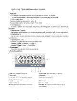
1 Technology parameters
Power supply voltage rating: 85-264VAC/50-60Hz or 12V (depends on the model#)
Relay output (NO+NC): 250VAC/3A
Relay switch life : 1×10⁵ cycles
SSR Voltage : 8V outline,Short line current : 30MA
Measurement accuracy : 0.2%FS
There are 4 LED indicator lamp on the front panel
Out range shown:“EEEE”
Ambient : Temperature of 0~50℃, humidity of 0~85RH%
Front panel: out Dimension 48mm×24mm×75mm , cut dimension 45mm×22mm
2 Front Panel And Operation
3 Manual setting the PID parameters
3.1 Setting initial function value(password 0089)
3.1.1 Table of initial function
symbol Code Description Parameters Initial
Inty Input type See table of Description of
initial function value
P10.0
outy Control mode 0, 1, 2, 3, 4 2
hy Control Hysteresis 0~9999 0.3
Psb Input Shift Adjustment -1000~1000 0.0
rd Heat cold 0 heat;1 cold 0
CorF Unit select 0 ℃;1 F 0
End The End

2
3.1.2 Description of initial function value
symbol name Input spec. Setting Range(℃)
t T type Thermocouple -200~400 Resistor
input 100K
r R type Thermocouple -50~1600
J J type Thermocouple -200~1200
W WRE 0~2300
b B type Thermocouple 350~1800
S S type Thermocouple -50~1600
K K type Thermocouple -200~1300
E E type Thermocouple -200~900 Current
output
0.2mA
Pt100 P100 -199~600
Pt10.0 P100 -199.9~600.0
Cu50 Cu50 -50.0~150.0
3.1.3 ouTY : out control mode
No. Out control mode
0 One line relay alarm output
1 one line relay PID output
2 One line relay alarm output;one line SSR PID output
3 One line relay output;one line SSR Hysteresis control
4 one line relay Hysteresis control output
3.1.4 Method of setting parameters

3
3.2 Setting PID Parameter(Password 0036)
3.2.1 Table of PID parameter
symbol Name Description parameters Initial
P P Proportional band 0.1~99.9% 5.0
I I Time of Integral 2~1999(s) 100
D Time of Derivative 0~399(s) 20
SOUF Overshoot depressant 0.0~1.0 0.2
OT Control period 2~199(s) 2
Flit Input digital filter 0~3 0
End End The End
3.2.2 PID PARAMETER
P;Proportional band Smaller P values will make the both integral and derivative action stronger, Larger the P number
means the weaker the action
I; Integral time Decrease integral time, if the controller is taking too long to eliminate the temperature offset. When I=0,
the system becomes a PD controller.
D;“d”. Derivative time Derivative action contributes the output power based on the rate of temperature change
Souf, Overshoot depressant
The value of souf is larger; the Overshoot depressant will be smaller. When the value of souf is too large, the Overshoot
depressant will be not enough. When the value of souf is smaller, the Overshoot depressant will be stronger.
OT,Control period
OT Small value can improve control accuracy,For SSR, thyristor or linear current output, generally 0.5 to 3 seconds. For
Relay output or in a heating/refrigerating dual output control system, generally 15 to 40 seconds, because small value
will cause the frequent on-off action of mechanical switch or frequent heating/refrigerating switch, and shorten its
service life. When OT is too small,the action is more,the life of relay will be short. If ouTY is set 1,OT is set 2~3
normally;If ouTY is set 2,OT is set 5~15 normally .If OUTY is set other selection ,OT is invalid
Flit; PV input filter. 0 No filter,1little, 2 middle, 3 strong. The value of Flit will determine the ability of filtering noise.
When a large value is set, the measurement input is stabilized but the response speed is slow.
Auto tuning; If the result of temperature control is not satisfy, you can start Auto tuning. Press > for more than 3 seconds to
active the auto-tuning process. After 2 cycles of on-off action, the instrument will obtain the values of PID control
parameters. During auto tuning, “At” will flash at lower display window and the instrument executes on-off control. If you
want to escape from auto tuning status, press > and hold for about 3 seconds until the "At" parameter appears again.
Note 1: If the setpoint is different, the parameters obtained from auto-tuning are possibly different. So you’d better set
setpoint to an often-used value or middle value first, and then start auto-tuning. For the ovens with good heat
preservation, the setpoint can be set to the highest applicable temperature. It is forbidden to change SV during auto
tuning. Depending on the system, the auto-tuning time can be from several seconds to several hours.
Note 2: Parameter HY (on-off differential, control hysteresis) has influence on the accuracy of auto-tuning. Generally, the
smaller the value of HY, the higher the precision of auto tuning. But the value of HY parameter should be large enough
to prevent the instrument from error action around setpoint due to the oscillation of input. HY is recommended to be 2.0.
Note 3: In a heating/refrigerating dual output system, auto tuning should be executed at the main output (OUTP).

4
3.3 Setting alarm and SV parameters(Password 0001)
3.3.1 Table of Alarm and Control parameter
symbol Code Description Setting range Initial
Sv Setting value In testing
Range
80.0
AHI Connect Value of Relay J1 80.0
AL1 Open Value of Relay J1 90.0
End End The End
3.3.2 Description of alarm and control parameter
SV;Set value of temperature
SV can be set either in here, or by only pressing “∧∨” to change
4 Wiring graph
/