SYL-1512A PID TEMPEARATURE CONTROLLER INSTRUCTION MANUAL
Version 2.2, July. 2007
Auber Instruments, 730 Culworth, Alpharetta, GA 30022
www.auberins.com e-mail: info@auberins.com Tel: 770-569-8420
WARNING
·Wiring precautions
-Install an external protection circuit if failure of this instrument could result in damage to your system.
-In order to prevent instrument damage or failure, protect the power line and the input/output lines from
high currents by using fuses with appropriate ratings. A very fast blowing fuse (such as an I
2
t fuse) is
needed when the output device is a solid-state relay (SSR). Please check with your fuse supplier for the
correct fuse for your SSR.
·Power supply
-Supply power of the specified rating.
-Do not turn on the power until all of the wiring is completed.
-Never use this instrument in the presence of inflammable gases or vapor.
-In order to prevent electric shock or burns, never touch the inside of the instrument.
-Do not attempt to modify this instrument.
·Maintenance
-Only authorized service engineers should replace parts.
-In order to use this instrument continuously and safely, conduct periodic maintenance. Some parts used
in this instrument have a limited service life and may deteriorate over time.
Caution
·Only clean the instrument when power is off.
·Please use a soft cloth or tissue to clean up stains on the display.
·Never use sharp & hard objects such as screwdrivers or ball pens to touch the buttons on the panel.
=============================================================
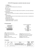
1. Features
◆ Compact size, 1/32 DIN that is only 24 x 48 x 75 mm (1x2 x3”)
◆ Supports 10 different types of commonly used temperature sensors, including Pt100 and Cu50 RTDs,
T、R、J、B、S、K、E、and WRe3-WRe25 thermocouples.
◆ The PID control output can be configured by user for either relay contact or SSR.
◆ The relay contact output can also be configured as the alarm output, or on/off control
◆ Auto-tune function can automatically find the best PID parameters.
◆ Temperature can be displayed in Fahrenheit and Celsius.
◆ Can be used with either DC or AC power source.
Figure 1
2. Specification
◆ Power supply:85~260VAC or 85~360VDC
◆ Power consumption:<2W
◆ Sampling rate:4 sample/sec
◆ Accuracy:0.2% full scale
1

◆ Display range:-1999~9999
◆ Display resolution:1 ℃ , 1℉, or 0.1 ℃ , 0.1℉ with Pt100 RTD sensor input.
◆ SSR driving output: 10VDC, 40 mA
◆ LED display:0.28” red color
◆ Out of range display:“EEEE”
◆ Working condition:0~50℃,≤85%RH
◆ Relay contact rating:220VAC @ 3A
◆ Outside dimensions:48×24×75mm
◆ Mounting cutout dimension:45×22mm
3. Front Panel and Operation
Figure 2
① AL- Relay J1 indicator
② Select next parameter/value increment.
③ Select previous parameter/value decrement
④ Digit shift/Auto tuning
⑤ Set/Confirm
⑥ OUT- Output indicator
(AT)- blinking during auto-tuning process
⑦ Parameter Display
4. Parameter Setting
a) Configuration Parameters
Table 1, Configuration Parameter Setting
Code Description Setting
Range
Initial
Setting
Note
Inty Input Type See table 2 K
outy Controlled output
device
0,1,2 2 1
Atdu Autotune offset 0~200(deg) 10 2
PSb Input offset -100~
100(deg)
0
rd Control function 0:heating
1:Cooling
0
CorF Display Unit 0:℃ 1:℉ 1
End Exit
Note 1.0:Relay J1 as alarm output; SSR output disabled。Can be used as On/Off control。
1:Relay J1 as PID controlled relay contact output. SSR output disabled.
2:Relay J1 as alarm output; SSR PID controlled with 12 V output.
Note 2.The autotune offset will shift the SV value down by the the Atdu value during the auto tune
2

process. That will preventing the system from damaging from over temperature during the autotune.
Press
,The enter code “0089” press again. Then, following the flow chart in Fig. 3
Figure 3 Setup flow chart
1) Press
to enter setting mode;
2) Press
、 and to enter parameters;
3) Press
to confirm;
4) Press
or to select the new parameter
Table 2, Temperature sensor code.
Symbol Description Working Temperature Range
t T Thermocouple -200~400 ℃; -320~752 ℉
r R Thermocouple -50~1600 ℃; -58~2900 ℉
j J Thermocouple -200~1200℃; -320~2200 ℉
WRE WRe3- WRe25
Thermocouple
0~2300℃; 32~4200 ℉
b B Thermocouple 350~1800℃; 660~3300 ℉
S S Thermocouple -50~1600℃; -58~2900 ℉
K K Thermocouple -200~1300℃; -320~2400 ℉
E E Thermocouple -200~900℃; -320~1650 ℉
P10.0 Pt100 RTD -99.9~600.0℃; -99.9~999.9 ℉
P100 Pt100 RTD -200~600℃; -320~1100 ℉
Cu50 Cu50 RTD -50.0~150.0℃; -60~300 ℉
b) PID Parameters
To enter PID parameter setting mode, press
, then enter code “0036”, press again. The parameter
3

flow chart is similar to Fig. 3
Table 3, PID and relevant parameters
Symbol Description Setting range Initial Setting note
P Proportional
Constant
0.1~99.9 (%) 5.0 4
I Integral time 2~1999(Sec) 100 5
d Derivative time 0~399(Sec) 20 6
SouF Damp constant 0.1~1.0 0.2 7
ot Cycle rate 2~199(sec) 2 8
FILT Digital filter
strength
0~3 0 9
End Exit
The values of the P, I, and D parameters are critical for good response time, accuracy and stability of
the system. Using the Auto-Tune function to automatically determine these parameters is recommended for
the first time user. If the auto tuning result is not satisfactory, you can manually fine-tune the PID constants
for improved performance.
Note 4. Proportional Constant (P): Represents the gain of the signal amplifier. Larger gain means the
controller will have more output power change for the same difference between set temperature (SV) and
measured temperature (PV). Smaller P value represents higher gain, or faster action.
Note 5. Integration time (I): Brings the system up to the set value by adding a constant to the output that is
proportional to how far the process value (PV) is from the set value (SV) and how long it has been there.
When I decreases, response speed is faster but the system is less stable. When I increases, respond speed is
slower, but system is more stable.
Note 6. Differentiation time (d): Responds to the rate of change of the process value so that the controller
can compensate in advance before |SV-PV| gets too big. A larger number increases its action. Setting
d-value too small or too large would decrease system stability, causing oscillation or even
non-convergence.
Note 7. Damp constant: This constant can help the PID control further improve the control quality. It helps
to damp the temperature overshoot. When its value is too low, the system might overshoot. When it is too
high, the system will be over damped.
Note 8. Control Period (also called cycle rate) (ot): When ot gets smaller, heating/cooling cycle is drive
faster, system respond speed is faster. For SSR output, ot is normally set at 2. But when using contact
control (Relays), contacts wear out faster so it is normally at 5~30 seconds.
Note 9. Digital Filtering (Filt): Filt=0, filter disabled; Filt=1, weak filtering effect; Filt=3, strongest
filtering effect. Stronger filtering increases the stability of the readout display, but causes more delay in the
response to changes in temperature.
c) Temperature setting and Alarm setting
To enter the temperature and alarm parameter setting mode, press
, enter the code “0001”, and press
4

again. The parameter flow chart is shown in Fig. 3
Table 4. Temperature and Alarm Parameter
Symbol Description Initial
setting
Note
SV Target temperature (Set
Value)
800 11
AH1 Alarm on temperature 800
AL1 Alarm off temperature 900
End Exit
Note 11. The SV can also be set directly during the normal operation mode. Press (^) or (v) key to switch
the display from process value (PV) to set value (SV). Press (^) or (v) key again to increase or decrease SV
by 1 degree.
i. Relay J1 value
① When AH1=AL1,relay is disabled,
② AH1>AL1 is for absolute high alarm. See fig. 4.
③ AH1<AL1 is for absolute low alarm. See fig. 5.
5. Auto-Tuning
Auto-Tuning function (also called self tuning) can automatically optimize the PID parameters for the
system. The auto-tuning function will heat up the system then let it cool down. It will repeat several
times. Based on the response time of the system, the built-in artificial intelligence program will
calculate and set the PID parameters for the controller.
Figure 6
A)To activate auto-tuning, press and hold
key until the “AT” indicator starts to blink, which indicates
auto-tuning is in progress. When “AT” stops blinking, the auto-tuning is finished. Now, newly calculated
PID parameters are set and are used for the system. Please note that Auto-tuning is only for PID control
mode (when “outy”is set at 1 or 2)
5

B) To stop the auto-tuning, press and hold key until “AT” indicator stops blinking. Then, the previous
PID parameters value are resumed,
6. Terminal Wiring (back view)
The polarity of power at terminal 1 and 2 do not matter.
Figure 7. Wiring diagram with thermocouple (TC) input on the left and RTD input on the right. Please
note that if the RTD is connected by two wires instead of three wires (for short distance application), the
terminal 6 and 7 need to be shorted.
7. Application Example
A furnace that can operate in the 0℃~1000℃ range needs to be controlled at 800℃. Alarm will go
off if T > 850℃, Power source is 220VAC,Heating element is switched by a SSR。K type thermocouple
is used as the temperature sensor.
a) Wiring diagram
Figure 8
b) Parameter setting,
(Inty)=K, (outy)=2, (Caty)=0, (PSb)=0, (rd)=0, (CorF)=0, (FILt)=0
Auto-tunig is used to set the PID parameters.
(SV)=800℃, (AH1)=850℃, (AL1)=848℃
Power up the controller. Press and hold the
key until “AT” starts to blink. The controller starts
the Auto-tuning. When the “AT” stops blinking, the new PID parameters are generated for the
system. The controller is in normal operation mode. The furnace will be maintained at 800℃。
For accessories, please check our web site at
www.auberins.com
6
1/6