Page is loading ...

© 2013 PORTER ATHLETIC, INC. ALL RIGHTS RESERVED. INST00476
7-16-2013
INSTALLATION INSTRUCTIONS
735 Spring Kit
No. 0073801
Remove Existing Springs
The first step in adding a spring kit to the 735 portable is to disconnect and remove the existing
springs. To do this, follow these steps:
1. Raise the unit to the upright position and lock the unit in place.
2. Place a protective mat or piece of cardboard under the springs to ensure the floor is not damaged
when the springs are removed.
3. Loosen (turn counterclockwise) the four jam nuts (B & C) to the end of the tension studs.
4. Remove the existing springs from the eye bolts.
5. Remove each of the tension stud clevis pins and the cotter pins which keep them in place; gently lower
the forward spring bar to the floor.
6. Remove the nuts and lock washers which attach the eye bolts to the frame; remove the eye bolts.
7. Swap out the old springs for the new springs.
Installing the New Springs
At this point the springs included in the spring kit need to be placed onto the front and rear spring
bars before attaching the spring carriage back onto the portable. To assist in showing the order in which
the springs and eye bolts are placed onto the rear spring bar, refer to Figure 1 below.
Figure 1: Spring Placement Diagram

© 2013 PORTER ATHLETIC, INC. ALL RIGHTS RESERVED. INST00476
7-16-2013
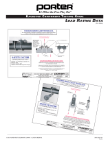
With the spring carriage assembled as shown in Figure 1, reattach the eye bolts first followed by the
tension studs. When tightening the jam nuts (B & C), set the initial adjustment distance to 4.5” (refer to
Figure 2 below). Then, carefully (with two or more adults) lower the unit and adjust the tension of the
springs as needed. Note: Never exceed an adjustment distance greater than 9” or the springs could be
permanently stretched and no longer function as intended.
Installation Is Complete
This concludes the installation of the spring kit. If the unit is difficult to raise or lower after installation,
follow the “Difficulty in Raising/Lowering the Backstop” sections from the owner’s manual.
601 Mercury Drive, Champaign, IL U.S.A., 61822
Toll Free: (888) 277-7778 xPhone: (217) 367-8438 xFax: (217) 239-2255
www.porterathletic.com
SAVE THESE INSTRUCTIONS FOR FUTURE USE
Figure 2: Initial Adjustment Distance of Forward Spring Bar
THIS WARNING IS GIVEN IN COMPLIANCE
WITH CALIFORNIA’S PROPOSITION 65:
WARNING
This product contains chemicals known to the
State of California to cause cancer, birth defects
or other reproductive harm.
WARNING: This product can expose you to Titanium Dioxide,
which is known to the State of California to cause cancer.
For more information go to www.p65warnings.ca.gov.
E

© 2013 PORTER ATHLETIC, INC. ALL RIGHTS RESERVED. INST00476
7-16-2013
Parts Reference Diagram:
/