Page is loading ...

Apr-08-2016 GI-50 320 DS (NZ308)_UL April 2016 Page 1Texmate, Inc. Tel. (760) 598-9899 • www.texmate.com
Table of Contents
✔TIGER FAMILY: More than 120 different Plug-in
I-Series Input Signal Conditioners are approved for
the Tiger Family of meters.
See I-Series Input Signal Conditioning Modules
Guide (Z87) for an up-to-date list.
Input Module Compatibility
• The Tiger 320 Operating System supports an easy to use
PC based Configuration Utility Program (which can be
downloaded FREE from the Texmate website) and pro-
gramming from front panel buttons.
• The T Version supports custom macro programs that can
be easily produced with the Tiger 320 Macro Development
System (available FREE on the Texmate website). The
Development System enables programs to be written in
BASIC, which can utilize any combination of the hundreds
of functions and thousands of registers embedded in the
Tiger 320 Operating System.
• Red, green, or superbright red 7-segment, 1” high LEDs
with full support for seven segment alphanumeric text.
• Brightness control of LED display from front panel buttons.
• Modular construction with more than 120 interchangeable
input
signal conditioners and more than 25 interchangeable
I/O modules.
• Up to 4 input channels with cross channel math for
multi-channel processing.
• For applications where sensor excitation is required,
modules are provided with 5V, 10V or 24 V DC
voltage outputs.
• On demand tare, calibration and compensation can be ini-
tiated by the front panel program button.
• Autozero maintenance for super stable zero reading is pro-
vided for use in weighing applications.
• Programmable input averaging and smart digital filtering for
quick response to input signal changes.
• Display text editing. Customize display text for
OEM applications.
• Scrolling display text messaging on T meters with macros.
• Auto-sensing high voltage or optional low voltage AC / DC
power supply.
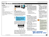
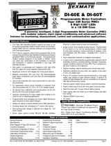
A powerful, intelligent, 5-digit Programmable Meter Controller (PMC)
with modular outputs, input signal conditioning and advanced software
features for monitoring, measurement, control and communication applications.
GI-50E & GI-50T
Programmable Meter Controllers
Tiger 320 Series PMCs
5 Digit 1” LEDs
in a 9/32 DIN Case
• Serial output options include RS-232, RS-485, ModBus or
direct meter-to-meter communications.
•
Single or dual 16-bit
Isolated Analog Outputs. Programmable
0~4 to 20mA or 0 to 10V for retransmission, 4-20mA loops
to drive valve actuators, remote controllers & displays, multi-
loop feedback and PID output. Scalable from 1 count to full
scale.
• Dual independent totalizers to integrate input signals.
• 6 super smart, independently programmable setpoints
with 8 selectable functions, including latching, deviation,
hysteresis, register resetting, tracking and dual PID. Plus 7
programmable timer modes on all 6 setpoints.
• Setpoint tracking, setpoint latching and manual relay reset.
• Setpoints activated from any input, any register in the meter
or from any digital input.
• Plug-in I/O modules include electromechanical or solid state
relays, logic outputs or open collector outputs. 6 inputs & 16
outputs of opto-isolated I/O can be connected to an external
DIN Rail terminal block module.
• Internal program safety lockout switch to prevent tampering.
• Peak & valley (max & min) with front panel recall and reset.
• Real time clock with 15 year Lithium battery backup.
• Data logging within the meter (up to 4000 samples with
date/time stamp).
• Optional NEMA-4 front cover.
• UL Listed
General Features
General Features ...................1
Specifications.....................2-3
Block Diagram of Tiger 320 Structure ...4
Controls & Indicators............... 6-7
Front Panel Configuration & Setup......8
Front Panel Programming Codes....9-10
Initial Setup Procedures ..........11-12
Display Brightness..................12
Calibration Modes ...............13-16
Programming Procedures.........17-29
Setpoint Programming Mode ......30-35
Registers .........................36
Functional Diagram.................37
Connector Pinouts..................37
Carrier Board Output Pins ...........38
Relay and Logic I/O Modules .........38
Component Layout & Ext. Devices ...39-40
Installation Guidelines ...............41
Index .........................42-43
Case Dimensions ..................44
TIGER FAMILY
E469078

Texmate, Inc. Tel. (760) 598-9899 • www.texmate.comPage 2 Apr-08-2016 GI-50 320 DS (NZ308)_UL April 2016
Development System for Custom
Macros
The Tiger 320 Macro Development System, which
may be downloaded free from our website, can be
used to create powerful macro software that allows
Tiger 320 T Versions to be easily customized to suit
any proprietary OEM application.
Installed Application Software
Includes
Counter Functions: Two built-in counters. UP count-
ers, DOWN counters, UP/DOWN counters and high
speed quadrature counters.
Data Logging: Logging with a date/time stamp, initi-
ated at timed intervals, by activation of a setpoint, or
manually. Data stored in internal 1MB EEPROM or in
a removable 4 to 128M Flash Card Memory Module.
Endless loop recording is supported.
Input Compensation: Provides compensation to the
primary input channel (CH1) via channels 2, 3 or 4.
Linearization: 4 selectable 32 point or one 125 point
flexible linearization tables are provided.
Logic I/O: 28 Macro programmable I/O ports sup-
ported.
Manual Loader: Front panel adjustable, 4 to 20mA or
0 to 10V isolated analog output.
Math Functions: Cross channel math functions to
calculate the sum, difference, ratio or the product of
two inputs.
On Demand Functions: Tare, compensation and
calibration.
Peak and Valley: The meter can retain peak and val-
ley (min/max) information and recall this on the front
panel.
Remote Setpoint Input: Remote setpoint input via
channel 2.
Serial Output Protocols: Selectable communication
modes include ASCII, Modbus (RTU), Master Mode
(for meter to meter communication) and an Epson
compatible printer driver.
Setpoint Functions: Six super smart setpoints with
fully configurable hysteresis, on and off delays, one
shot, pulse and repeat timers, latching, dual PID,
setpoint tracking, resetting of registers, initiating of
logging and printing.
Signal Conditioning Functions: Averaging, smart
filter, rounding, square root,auto zero maintenance.
Timer: Timer functions supported in either time-up,
time-down, or real-time clock modes.
Totalizer: Two totalizers for running total and batch
totals of a process signal that can be accumulated
over time.
Display
Digital Display: 7-segment, 1” (25.4 mm) LEDs.
Display Color: Red (std). Green or Super-Bright Red
(optional).
Digital Display Range: -19999 to 99999
Update Rate: 3 to 10 times per second
Display Dimming: 8 brightness levels. Front Panel
selectable
Scrolling Display Text Messaging: Full alphanu-
meric, 7-segment text characters supported on T
Version with macros.
Polarity: Assumed positive. Displays - negative
Decimal Point: Front panel, user selectable to five
positions.
Annunciators: 6 red LEDs on front panel; one per
setpoint.
Overrange Indication:
Underrange Indication:
Front Panel Controls: PROGRAM, UP and DOWN.
Operating System (Tiger 320)
Processor: 32 bit with floating point maths (18.4
MHz).
Flash Memory: 64k, 4k for use by custom macros.
RAM: 1.25k and FeRAM 4k.
EEPROM: E Version 4k standard, T Version 32k
standard. Memory upgrades available to 32k for LIN
Tables and 1MB for Data Logging and custom macros.
Registers: 6144 registers comprised of 8, 16 or 32
bit signed, unsigned or floating point registers, imple-
mented in a combination of RAM, FeRAM, Flash and
EEPROM.
Internal communication BUS: 32 bit I2C BUS
Real Time Clock (option):
Year:Month:Date:Hour:Minute:Second with 15 yr
Lithium battery backup.
Conguration: Supports Front Panel Programming
Codes and a PC-based Configuration Utility Program,
which may be downloaded free from our website. T
Version also supports custom macros.
Specifications

Apr-08-2016 GI-50 320 DS (NZ308)_UL April 2016 Page 3Texmate, Inc. Tel. (760) 598-9899 • www.texmate.com
Inputs
Inputs Available: More than 120 single, dual, triple
and quad input signal conditioners available covering
all types of analog, digital and mixed input signals.
Accuracy: Tiger 320 PMCs enable the user to estab-
lish any degree of system accuracy required. Built-in
compensation and linearization functions enable sys-
tem accuracies of the order of ±0.0001% of reading for
analog inputs. Stop -Start time resolution from ±1sec
to ±0.7nsec. Digital input and pulse counts ±1 count.
A/D Convertors: A Dual Slope, bipolar 17 bit A/D
is provided as standard on the main board. SMART
modules can have 24 bit or 16 bit Delta-Sigma A/D
convertors that utilize the internal I2C BUS.
Temperature Coefficient: Typically 30ppm/˚C.
Compensation can be utilized to achieve system tem-
perature coefficients of 1ppm.
Warm Up Time: Up to 10 minutes, depending on
input module.
Conversion Rate: Typically 10 samples per second.
However, SMART input modules are available that can
convert at 60, 240, 480 or 960 samples per second.
Control Output Rate: Can be selected for 100msec
or 10msec. Some SMART modules have SSR outputs
that react within 1.2msec.
Excitation Voltage: Depends on input module select-
ed. Typically, 5V, 10V or 24VDC is provided.
Outputs
(See pages 38-39 for pinouts and details of modular
construction)
Standard Carrier Board: Is available without a serial
output, or with either an isolated RS-232 or an isolat-
ed RS-485 (RJ-6 socket).
Two Isolated Analog Output Options: Mounted on any
carrier board.
1. Single Analog Output: Fully scalable from 4 to
20mA or 0 to 20mA (or reverse) and selectable for 0
to 10VDC (or reverse).
2. Dual Analog Output: Fully scalable from 0 to 10VDC
(or reverse).
Analog Output Specications: Accuracy: 0.02%
FS. Resolution: 16-bit Delta-Sigma D/A provides
0.4µA on current scaling, 250µV on voltage scaling.
Compliance: 500Ω maximum for current output.
500Ω minimum for voltage output. Update Rate:
Typical 7 per second. Step Response: Typical
6msec to a display change. Scalable: From 1 count
to full scale.
Outputs continued
Seven I/O Modules: Plug into any carrier board from
rear.
1. Four Relay Module: Available in six combinations
from one relay up to a total of two 9/10A Form C
Relays* and two 4/5A Form A Relays**.
2. Four Relay Module: Available with one to four 5A
Form A Relays**.
3. Six Relay Module: Available with five or six 4A Form
A Relays**.
*Form C Relay Specications: 9/10A 240VAC~1/2
HP, 8A 24VDC. Isolation 3000V. UL and CSA listed.
**Form A Relay Specications: 4/5A 240VAC, 4A
24VDC. Isolation 3000V. UL and CSA listed.
4. Four Solid State Relay (SSR) Module: Available with
one to four independent (210mA DC only) SSRs (300V
max).
5. Six Output 5VDC / TTL or Open Collector: Available
with 0 to 5VDC (50 mA) or 0 to V+ (5VDC max, 50
mA).
6. Opto Isolated I/O Module: Available in either 6 Outputs
& 6 Inputs, or 16 Outputs and 6 Inputs. For connection
to an external breakout box.
7. Flash Card Memory Module: Available with 8 or 16
MB memory.
Power Supplies
Auto sensing AC/DC (DC to 400Hz) hi volts std, low
volts optional.
PS1 (standard): 95-300VDC / 85-265VAC, 50-400Hz,
2.5W nominal
PS2 (optional): 10-72VDC / 14-48VAC, 50-400Hz,
2.5W nominal.
Environmental (See Rear page for IP-65 & NEMA-4
options)
Operating Temperature: 0 to 50 ˚C (32 ˚F to 122 ˚F).
Storage Temperature: -20 ˚C to 70 ˚C (-4 ˚F to 158
˚F).
Relative Humidity: 95% (non-condensing) at 40 ˚C
(104 ˚F).
Mechanical (See Rear page for more details)
Case Dimensions: 9/32 DIN, 144x72mm (5.69” x
2.84”)
Case Material: 94V-0 UL rated self-extinguishing
polycarbonate.
Weight: 11.5 oz (0.79 lbs), 14 oz (0.96 lbs) when
packed.
Certications and Listings
CE: As per EN-61000-3/4/6 and EN-61010-1.
UL: E469078
Specifications continued

Texmate, Inc. Tel. (760) 598-9899 • www.texmate.comPage 4 Apr-08-2016 GI-50 320 DS (NZ308)_UL April 2016
Block Diagram of the Tiger 320 Series Software and Hardware Structure
RESIDENT TIMER 1
RESIDENT TIMER 2
Runs ONLY if selected on CH3,
or CH4. Resolution 1 sec
I2C
BUS
LOGIC I/O
FROM
MODULES
Prescaler
Channel 1 & 2
17 BIT ON BOARD
DUAL SLOPE A to D
REF IN
CHANNELS
RESULT
CHANNEL
1 2 3 4
CHANNELS 1 2
1 2
3 4
1R
R
2 3 4
1R
D
D
2 3 4
1R
DEFAULT
DISPLAY
CHANNEL
DEFAULT
DISPLAY
CHANNEL 234
DISPLAY FORMATTING
I2C
MICRO
Sigma Delta
A to D
16 to 24 Bit
Signal
Conditioning
REF
SSR SSR
REF
Sig
Con
SMART MODULES WITH MULTICHANNEL INPUTS,
AN ON-BOARD A TO D CONVERTER,
MICROPROCESSOR, AND TWO
SOLID STATE RELAY OUTPUTS
Signal
Conditioning
MULTI-INPUT MODULES
W/DIGITAL SCALING
MUX
REF
PULSE
Signal
Conditioning
SINGLE INPUT MODULES
WITH ANALOG SCALING
REF
ZERO
SPAN
Signal
Conditioning
REF
RAW DATA ANALOG, DIGITAL
AND LOGIC I/O
MACRO PROCESSING
DATA LOGGING
Manual or auto, Up to 4000
samples, Date and Time
stamp, endless loop record,
Burst downloading
SERIAL COMMUNICATION
Read and write into all registers
ASCII, MODBUS,
Meter TO Meter Communication,
ETHERNET (TCP/IP), Epson Compatible
Serial Printer Driver
SETPOINTS
Up to 6 relay, SSR,
TTL or open collector.
PID, deviation, trigger, pulse,
tracking, hysteresis, latching,
timer modes, reset,
High/low/deviation activation
TOTALIZER 1
TOTALIZER 2
Two independent totalizers
Linearizing
4 Tables of 32 Points each
or 1 Table of 125 Points
Internal System Clock
Downloads from Real Time Clock
or starts from 12:00 on power up.
Can be displayed on CH3, CH4
Optional Real-time clock
with date and time stamp
Rear Pins
Hold, Test, Lock & Capture.
The Lock, Hold and Capture
pins can be reprogrammed
for use as Digital Logic I/O pins.
ANALOG OUTPUT
Voltage or current,
single or dual
PLUG IN OPTO-ISOLATED
I/O 6 IN 6 OUT OR 6 IN 16 OUT
DISPLAY DRIVE
SMART MODULES WITH AN ON BOARD
MICROPROCESSOR AND TWO SOLID STATE
RELAY OUTPUTS WITH PULSE, OR QUADRATURE
ENCODER INPUTS FOR COUNTING, FREQUENCY OR POSITION
I2C
MICRO
Signal
Conditioning
SSR SSR
REF
Sig
Con
Signal
Conditioning
Cross Channel Math
1+2, 1-2, 1x2, 1/2, 1=R
RESET
with UP/DOWN
Peak, Valley,
Tare, Totalizers
VIEW MODE
to view
selected
function values
P and UP Buttons
to enter setup
menu.
P and DOWN
Buttons to enter
setpoint menu.
PROGRAM
BUTTON
MACRO_
PROCESSING
Including
EDIT MACRO
F1_BUTTON
MACRO_
PROCESSING
F2_BUTTON
MACRO_
PROCESSING
F3_BUTTON
MACRO_
PROCESSING
ON DEMAND
FUNCTIONS
Hold down the
PROGRAM
button for 4 secs
to initiate Auto
tare, Auto
Calibration,
Manual Loader or
Input Channel
Compensation
PROGRAM LOCK
If Program lock is ON values are
displayed, but cannot be changed
SETPOINT LOCK
If Program lock is ON values are
displayed, but cannot be changed
Prog
F1 F2 F3
RESULT PROCESSING
of Cross Channel Math
Select data source for
OUTPUT PROCESSING
Select data source for: Setpoint 1, 2, 3, 4, 5, 6;
Analog output 1, 2; Data logging
Select data source for
DISPLAY PROCESSING
Select data source for:
Display 1 (Default Display Channel D), Display 2,
Display 3, Peak, Valley, Totalizer 1, Totalizer 2,
AVERAGING,
CALIBRATION (SCALE and OFFSET),
INVERSE OF INPUT, LINEARIZATION,
LOG OF INPUT (Bargraph display only)
RTD, SAMPLE RATE, SMART AUTO ZERO,
SQUARE ROOT, THERMOCOUPLES
DECIMALS, , RIGHT HAND CHARACTER, AND ROUNDING
FOR CH1, 2, 3, 4, RESULT AND DEFAULT DISPLAY
CUSTOM TEXT FOR CH1, 2, 3, 4, RESULT, PEAK, VALLEY,
TOTALIZER 1, TOTALIZER 2, SP1, SP2, SP3, SP4, SP5, SP6
DIGITAL PROCESSING
Select from R, 1, 2, 3, 4, Totalizer 1, 2, Peak,
Valley, Tare or any usable registers from 1 to 244
Select from R, 1, 2, 3, 4, Totalizer 1, 2, Peak,
Valley, Tare or any usable registers from 1 to 244
Code1
SPC_1 to 6
SPC_1 to 6
Code1
Code7
Code2
Code4
Code5
Code6
Code8
CAL
CAL
CAL
CAL
CAL
CAL
CAL
CAL
Linearization
24 bit registers in EEPROM that store
the four 32 point LIN tables.
Registers 257 to 512
OPERATING SYSTEM USE ONLY
DO NOT write to these registers, as
any alteration to their data may make
the meter inoperative.
Registers 1125 to 2048
OPERATING SYSTEM USE ONLY
DO NOT write to these registers, as
any alteration to their data may make
the meter inoperative.
Registers 4097 to 5120
Multi function, multi type Registers
that may only be accessed through
the serial port or by macros. Their
functions are detailed in the Register
Supplement.
Registers 513 to 1124
Macro Code Storage
16 bit unsigned. In Flash RAM
Registers 2049 to 4096
16 bit unsigned. May be
accessed by macros or
Serial Port.
Registers 5120 to 6144
Code9
Code5
Code6
FLASH
Result of Cross
Channel Math
AVERAGING, CALIBRATION (SCALE & OFFSET),
INVERSE of R, LOG OF R (Bargraph display only)
LINEARIZING of R,
SMART AUTO ZERO,
SQUARE ROOT of R,
SP1
SP2
SP3
SP4
SP5
SP6
Registers 1 to 244
Registers from 1 to 244 may be selected
manually as a data source for setpoint
or output processing. However only
those registers shown below contain
data applicable for use as data source.
Setpoints
6 to 11- SP1,2,3,4,5,6 value
65 to 70- SP1,2,3,4,5,6 Hysteresis,
71 to 76- delay on make SP1,2,3,4,5,6
77 to 82- delay on break SP1,2,3,4,5,6
Input Channels
18,19,20,41,42- Raw Result,CH1,2,3,4
21 to 23,43,44- Scaled Result,CH1,2,3,4
45,46- Prescaler CH1,2
Smart modules
54 to 60- Smart Output 1,2,3,4,5,6,7
Analog Outputs
83, 84 - Analog Output 1 & 2
Variables (Used with Macro Only)
85 to 94 - Variable 1 to Variable 10
Timers
95 & 96 - Timer 1, 2
Real time Clock
213 to 219 - Real Time Clock
Auto Zero Offset
227 to 231 - Auto Zero Offset for Result,
CH1, CH2, CH3 & CH4
Operating System
NOT USABLE as a data source.
15,38,47,48,52,53,61-64,123-128,140,
141,160,161,234-244
6144 REGISTERS
Registers are comprised of 8, 16 or
32 bit signed, unsigned or floating
point registers, implemented in either
Flash RAM, RAM, FeRAM, EEPROM
or NVRAM (Real time clock option).
See the Register Supplement for
detailed information on ALL registers
All registers may be accessed, and
read or written to via the serial port,
and by user developed macros.
The registers used for the operating
system should not be written into, as
modification of their data may render
the meter inoperative.
LOG BARGRAPH DISPLAY, dB DISPLAY, OCTAL.
BRIGHTNESS, ANNUNCIATORS, TREND
SCALE, OFFSET FOR CH1, 2, 3, 4 AND RESULT
A macro can access all functions and read
and write into all registers. Macro Timer1,
Macro Timer2 have 0.1 second resolution.
Macros allow a user to customize a meter
for a specific application using the Tiger 320
Development System. Macros may be locked
to prevent access by anyone.
ANALOG, DIGITAL
AND LOGIC I/O

Apr-08-2016 GI-50 320 DS (NZ308)_UL April 2016 Page 5Texmate, Inc. Tel. (760) 598-9899 • www.texmate.com
THIS PAGE INTENTIONALLY LEFT BLANK

Texmate, Inc. Tel. (760) 598-9899 • www.texmate.comPage 6 Apr-08-2016 GI-50 320 DS (NZ308)_UL April 2016
ON
12
PROGRAM
LOCKOUT
Switch
SETPOINT
LOCKOUT
Switch
Seven Segment
LED Display
Display PCB without Faceplate and Bezel
Program Button
While programming, pressing the
P
button saves the current program-
ming settings and moves to the next programming step.
You can move through the programming codes using the program button.
The codes you pass are not affected, unless you stop and make changes
using the or buttons.
Pressing the
P
and button at the same time initiates the main
programming mode. To save a new configuration setting and return
to the operational display, press the
P
button once and then press
the
P
and button at the same time.
Pressing the
P
and button at the same time initiates the setpoint
programming mode. To save a new configuration setting and return
to the operational display, press the
P
button once and then press the
P
and button at the same time.
See Display with Faceplate and Bezel diagram.
Up Button
When setting a displayed parameter during programming, press the
button to increase the value of the displayed parameter.
When in the operational display, pressing the button initiates a
viewing mode that allows you to view the readings on channels 1
and 3, setpoints 1, 3, and 5, peak, and total 1. Once into the viewing
routine, pressing the button moves through each displayed parameter.
See Display with Faceplate and Bezel diagram.
Down Button
When setting a displayed parameter during programming, press the
button to decrease the value of the displayed parameter.
When in the operational display, pressing the button initiates a
viewing mode that allows you to view the readings on channels 2
and 4, setpoints 2, 4, and 6, valley, and total 2. Once into the viewing
routine, pressing the button moves through each displayed parameter.
See Display with Faceplate and Bezel diagram.
Annunciator LEDs
The annunciator LEDs can be programmed to indicate the alarm status.
Setpoint 1 can be configured to indicate the rising signal trend.
Setpoint 2 can be configured to indicate the falling signal trend. They
are labeled from left to right: SP1, SP2, SP3, SP4, SP5, SP6.
See Display with Faceplate and Bezel diagram.
Program Lockout Switch
When the PROGRAM LOCKOUT switch is set to position 2, all pro-
grammable meter functions can be changed.
When set to the ON position, the PROGRAM LOCKOUT switch pre-
vents any programming changes being made to the meter. If program-
ming is attempted, the meter displays [LoC]. The ON position allows
programming parameters to be viewed but not changed.
See Display PCB without Faceplate and Bezel diagram.
Controls and IndicatorsControls and Indicators
Front Panel Controls and Indicators
SP1 SP2 SP3 SP4 SP5 SP6
Prog.
UP
Button
DOWN
Button
P
PROGRAM
Button
Display with Faceplate and Bezel
LED Annunciators
for Setpoints 1- 6
Display with Faceplate and Bezel
SP1 SP2 SP3 SP4 SP5 SP6
Prog
Optional Membrane Touch Pad Faceplate
UP
Button
DOWN
Button
P
PROGRAM
Button
LED Annunciators
for Setpoints 1-6
LED Display
The meter has a 5-digit, 7-segment, 1” (25.4 mm) standard red,
or optional green or superbright red LED numeric display. The
LED displays are used to display the meter input signal read-
ings. They also display the programming codes and settings
during meter programming.
Display Text Editing with 7 Segment
Alphanumeric Display Characters
Display text, such as setpoints, can be easily edited to suit your
application, by connecting the meter to a PC running the free
downloadable Configuration Utility program.
For Example:
Instead of [SP_1]
could be used for
TANK LOW
Instead of [SP_2]
could be used for
BRAKE OFF
OR
SP1 SP2SP3SP4 SP5SP6
Prog.
SP1 SP2SP3SP4 SP5SP6
Prog.
Scrolling Display Text Messaging
Scrolling display text messaging can be configured to run with
a simple macro.
SP1 SP2SP3SP4 SP5SP6
Prog.
Display Text Characters
The following text characters are used with the 7-segment display.
7-SEGMENT DISPLAY CHARACTERS

Apr-08-2016 GI-50 320 DS (NZ308)_UL April 2016 Page 7Texmate, Inc. Tel. (760) 598-9899 • www.texmate.com
(full scale) signal
must be at least 1000
counts greater than
the low input (zero)
signal (positive and
negative values are
allowed).
2) The scaling requirement exceeded the capability of the meter (–19999
to +99999).
3) No input signal present, or incorrect connections.
24 25
Input Module (See I-Series
Input Module Supplement
for connection details)
28 29 30 31 32 33 34 35
AC/DC
POWER
39 40 41
38 42
37
Relay Outputs
Serial Output
Function Pins
LOCK
HOLD TEST COM
CAPTURE
45 4644
Dual Analog
Output ONLY
Analog Output
18 19 20
2726
21 22
12 13 14
910 11
456
12315 16
Rear Panel
Setpoint Lockout Switch
When the SETPOINT LOCKOUT switch is set to position 1, the
setpoints can be programmed. Once the setpoint values have been
entered and the SETPOINT LOCKOUT switch set to the ON position,
the setpoints can be viewed but not changed.
See Display PCB without Faceplate and Bezel diagram.
Error Message [Err]
Error messages usually occur during calibration procedures. The
three most likely causes of an error message are:
1) The full scale and
zero signals were too
similar.
Note, the high input
SP1 SP2SP3 SP4 SP5SP6
Prog.
Test Pin
Configure Code 9 to [0XX]. When the TEST pin (pin 20) is con-
nected briefly to the COMMON pin (pin 21) all segments of the
display and setpoint annunciators light up. Five eights and five
decimal points (8.8.8.8.8.) are displayed for a short period. The
microprocessor is also reset during this time, losing all RAM set-
tings such as peak and valley, and any digital input pin settings set
up in Code 9.
The TEST pin can also be configured in Code 9 to carry out the
following (see Meter Programming Codes on Page 9):
• Reset counter channel 1 and total 2 at power-up [1XX].
• Reset counters, CH1, CH2, CH3, CH4, total 1, and total 2 at
power-up [2XX].
• Reset total 1 and total 2 at power-up [3XX].
Capture Pin
When the CAPTURE pin (pin 22) is connected to the COMMON
pin (pin 21), the CAPTURE pin can be programmed for setpoint/
relay activation or macro control applications in the setpoint control
settings mode of the setpoint programming mode [SPC_X] [X2X] .
Common Pin
To activate the LOCK, HOLD, TEST and CAPTURE pins from the
rear of the meter, the respective pins have to be connected to the
COMMON pin (pin 21).
The LOCK pin can also be configured in Code 9 to carry out the
following functions (see Meter Programming Codes on Page 9):
• Reset channel 1 [XX1].
• Reset channel 2 [XX2].
• Reset channel 3 [XX3].
• Reset channel 4 [XX4].
• Reset tare [XX5].
• Reset total 1 [XX6].
• Unlatch (de-energize) all setpoints [XX7].
Hold Pin
Configure Code 9 to [X0X]. When the HOLD pin (pin 19) is con-
nected to the COMMON pin (21) the displayed reading is frozen.
However, A/D conversions and all control functions continue and
as soon as pin 19 is disconnected from pin 21 by the switch, the
updated reading is instantly displayed.
The HOLD pin can also be configured in Code 9 to carry out the
following functions (see Meter Programming Codes on Page 9):
• Reset channel 1 [X1X].
• Reset total 1 and total 2 [X2X].
• Reset total 2 [X3X].
• Reset peak and valley [X4X].
• Reset tare [X5X].
• Set tare [X6X].
• Unlatch (de-energize) all setpoints [X7X].
The main programming mode can be entered, but only the bright-
ness setting adjusted. After adjusting the brightness setting, press-
ing the
P
button displays [LoCK].
Lock Pin
By configuring Code 9
to [XX0], connecting the
LOCK pin (pin 18 on
the main PCB) to the
COMMON pin (pin 21
on the main PCB), both
the main and setpoint
programming modes
are locked out. All meter
programming codes and setpoints can be viewed but not changed.
Rear Panel External Switched Inputs
Controls and IndicatorsControls and Indicators continued
SP1 SP2SP3SP4 SP5 SP6
Prog.
Display Showing [LoCK] Message
Display Showing Error Message

Texmate, Inc. Tel. (760) 598-9899 • www.texmate.comPage 8 Apr-08-2016 GI-50 320 DS (NZ308)_UL April 2016
P
To explain software programming procedures, diagrams are used
to visually describe the programming steps. The following conven-
tions are used throughout the range of Tiger 320 Series document
diagrams to represent the buttons and indicators on the meter,
and the actions involved in programming the meter:
Text or numbers shown between square brackets
in a description or procedure indicate the pro-
gramming code name of the function or the value
displayed on the meter display.
Symbol Explanation
SP1 SP2 SP3 SP4 SP5 SP6
Prog.
Operational Display The display showing 99999 represents the
OPERATIONAL DISPLAY. After the meter
has been powered up, the display settles and
indicates the calibrated input signal. This is
known as the operational mode and is gen-
erally referred to as the operational display
throughout the documentation.
This symbol represents the UP button.
Shown in a diagram, pressing the UP button is
always indicated by a right hand.
This symbol represents the DOWN button.
Shown in a diagram, pressing the DOWN but-
ton is always indicated by a right hand.
Where two right hands are shown on the same
diagram with the word OR between them, this
indicates that both the and buttons can
be used to adjust the display: UP for increase,
DOWN for decrease.
This symbol represents the PROGRAM button.
In a procedure, pressing the program button is
always indicated by a left hand. A number indi-
cates how many times it must be pressed and
released, or for how long it must be pressed
before releasing.
[Span]
[10000]
When two displays are shown
together as black on grey, this
indicates that the display is
toggling (flashing) between the
name of the function and the
value or configuration setting.
Where a number is not defin-
able, the default setting [000]
is shown.
If an X appears in the description of a
3-digit programming code or in a configu-
ration procedure, this means that any num-
ber displayed in that digit is not relevant to
the function being explained, or more than
one choice can be made.
SP1 SP2SP3SP4 SP5SP6
Prog.
Where a left and right hand are shown on separate buttons
on the same diagram, this indicates that the buttons must be
pressed at the same time.
The exceptions to this rule are when carrying out the Model
and Software Code Version Check, or the Code Blanking and
Macro Check.
Programming procedures are graphic based with little descrip-
tive text.
Each procedure shows a number of meter panel displays running
in procedural steps from the top to the bottom of the page.
If need be, the procedure may run into two columns with the left
column running down the page and continuing at the top of the
right-hand column. Each action performed by the user is shown
as a numbered step.
Each procedural step shows the meter display as it looks before
an action is performed. The hand or hands in the procedural step
indicate the action to be performed and also how many times, or
for how long, the button is to be pressed.
For example, the diagram below shows the meter in the operation-
al display. With a left hand pressing the
P
button and a right hand
pressing the button, the user is entering the main programming
mode. This is indicated by the next diagram displaying [bri] and [5].
This is the display brightness mode and is the first sub-menu of
the main programming mode.
The meter uses a set of intuitive
software codes to allow maximum
user flexibility while maintaining
an easy programming process.
To configure the meter’s program-
ming codes, the meter uses the
three right-hand side display digits.
These are known as the 1st, 2nd,
and 3rd digits and can be seen in
the diagram opposite.
SP1 SP2 SP3 SP4 SP5 SP6
Prog.
Operational Display
First
Digit
Second
Digit
Third
Digit
SP1 SP2 SP3 SP4 SP5 SP6
Prog.
SP1 SP2 SP3 SP4 SP5 SP6
Prog.
SP1 SP2 SP3 SP4 SP5 SP6
Prog.
Operational Display
Press
4 secs
Press
2
SP1 SP2 SP3 SP4 SP5SP6
Prog.
SP1 SP2SP3SP4 SP5SP6
Prog.
SP1 SP2SP3 SP4 SP5SP6
Prog.
Step 1
Operational Display
Press
at same
time
Press
at same
time
Step 2 Press
2
SP1SP2 SP3SP4 SP5SP6
Prog.
SP1 SP2SP3SP4 SP5SP6
Prog.
OR
All programming modes are entered from this level.
Front Panel Push Button Configuration and Setup for Programming Conventions

Apr-08-2016 GI-50 320 DS (NZ308)_UL April 2016 Page 9Texmate, Inc. Tel. (760) 598-9899 • www.texmate.com
Main Programming Mode
Calibration Modes for Input and Output
Code 1 – Display Conguration
Code 2 – CH1 Measurement Task & Sampling Rate
Code 3 – CH1 Post Processing & Serial Mode Functions
Code 4 – CH2 Measurement Task & Sampling Rate
Code 5 – CH3 Functions
Code 6 – CH4 Functions
Code 7 – Result Processing
Code 8 – Data Logging & Print Mode
Code 9 – Functions for Digital Input Pins
[CAL]
[Cod_1]
[Cod_2]
[Cod_3]
[Cod_4]
[Cod_5]
[Cod_6]
[Cod_7]
[Cod_8]
[Cod_9]
Setpoint Programming Mode
Setpoint 1
[SP_1]
Setpoint Activation Values
Setpoint 2
[SP_2]
Setpoint 3
[SP_3]
Setpoint 4
[SP_4]
Setpoint 5
[SP_5]
Setpoint 6
[SP_6]
Enter these menus to adjust
SP activation values
Setpoint 1
[SPC_1]
Setpoint & Relay Control Function Settings
Setpoint 2
[SPC_2]
Setpoint 3
[SPC_3]
Setpoint 4
[SPC_4]
Setpoint 5
[SPC_5]
Setpoint 6
[SPC_6]
Enter these menus to con-
figure SP control values
Display Brightness
[bri]
The meter’s programming codes are divided into two modes:
the main programming mode, and the setpoint program-
ming mode. (See diagram below).
Each mode is accessible from the operational display.
Main Programming Mode
The main programming mode provides access to program all
meter functions, except setpoints.
Setpoint Programming Mode
The setpoint programming mode provides access to program
all setpoint and relay functions.
Code 10 – Bargraph Setup
[Cod10]
Code 10 applies to Tiger 320 Series meters with bargraph displays
only. See data sheets for DI-50EB51, DI-50TB51, FI-B101D50E,
and FI-B101D50T.
SP1 SP2 SP3 SP4 SP5 SP6
Prog.
Operational Display
P
SP1 SP2 SP3 SP4 SP5 SP6
Prog.
Operational Display
P
P
P
P
P
P
P
P
P
PP
P
P
P
P
P
P
P
P
P
P
P
P
The Setpoint and
Relay Control
Settings diagram
on Pages 34 and
35 shows the
three digit cong-
uration settings
that are applied
individually to
each setpoint.
See Page 33 for
an example proce-
dure to configure a
setpoint for simple
relay functions.
Front Panel Programming Codes
To enter or exit the Main
Programming Mode, press
P
and at the same time
To enter or exit the Setpoint
Programming Mode, press
P
and
at the same time
To save a new setpoint
configuration setting and
return to the operation-
al display at any point,
press the
P
button once.
Then press the
P
and
button at the same
time to exit.
Save SP Settings & Exit
To save a new main pro-
gramming mode configu-
ration setting and return to
the operational display at
any point, press the
P
button once.
Then press the
P
and
button at the same time
to exit.
Save Code Settings & Exit
Programming Tip
The easiest and fastest way to configure the
Tiger 320 is to use a PC with the free download-
able configuration utility program.
Programming Tip
Programming Tip

Texmate, Inc. Tel. (760) 598-9899 • www.texmate.comPage 10 Apr-08-2016 GI-50 320 DS (NZ308)_UL April 2016
View Modes
While in the operational display, pressing the button allows
you to view but not change the following parameters:
• Channel 1.
• Channel 3.
• Setpoint 1.
• Setpoint 3.
• Setpoint 5.
• Peak (of CH1).
• Total 1 (total of CH1).
While in the operational display, pressing the button allows
you to view but not change the following parameters:
• Channel 2.
• Channel 4.
• Setpoint 2.
• Setpoint 4.
• Setpoint 6.
• Valley (of CH1).
• Total 2 (total of CH2).
SP1 SP2 SP3 SP4 SP5 SP6
Prog.
Operational Display
Press
4 secs
SP1 SP2 SP3 SP4 SP5 SP6
Prog.
Operational Display
Press
1
After configuring an on demand
function in the Calibration On
Demand Mode, press the
P
button for 4 seconds to
activate one of the following
selected on demand modes.
Tare
Single-point calibration
Two-point calibration
Primary input compensation
Manual loader (manual offset)
Print
CH3
SP_1
SP_3
SP_5
PEAK
TOT_1
CH1
To view, press
the button:
SP1 SP2 SP3 SP4 SP5 SP6
Prog.
Operational Display
Press
1
View Mode
CH4
SP_2
SP_4
SP_6
VALEY
TOT_2
CH2
To view, press
the button:
On Demand Modes
The meter can be programmed to activate the following func-
tions on demand by pressing the
P
button for 4 seconds:
• Tare.
• Single-point calibration.
• Two-point calibration.
• Primary input compensation.
• Manual loader (manual offset).
• Print.
The on demand function is selected in the calibration mode.
OR
OR
OR
OR
OR
P
SP1 SP2 SP3 SP4 SP5 SP6
Prog.
Operational Display
SP1 SP2 SP3 SP4 SP5 SP6
Prog.
Operational Display
P
SP1 SP2 SP3 SP4 SP5 SP6
Prog.
Operational Display
P
On Demand Modes
Front Panel Programming Codes continued
For a full breakdown of all programming codes, see the
Tiger 320 Series Programming Code Sheet (NZ101).
View Mode

Apr-08-2016 GI-50 320 DS (NZ308)_UL April 2016 Page 11Texmate, Inc. Tel. (760) 598-9899 • www.texmate.com
Initial Setup ProceduresInitial Setup Procedures
SP1 SP2SP3SP4 SP5 SP6
Prog.
SP1 SP2 SP3SP4 SP5SP6
Prog.
SP1 SP2 SP3SP4 SP5SP6
Prog.
SP1 SP2SP3SP4 SP5SP6
Prog.
SP1 SP2SP3SP4 SP5SP6
Prog.
MODEL AND SOFTWARE CODE VERSION CHECK PROCEDURE
MODEL &
SOFTWARE
CODE VERSION
CHECK
Press
then
once
release
Press
and
hold
Step 1
Step 2
Step 3
The above displays toggles
three times before returning to
the operational display
SP1 SP2SP3SP4 SP5SP6
Prog.
Operational Display
Operational Display
Example
Release
after
pressing
Prog.
Model
Number
Typical
Software
Version
Number
Press and hold
the and
buttons
While holding both
buttons, press the Prog.
button then release
all three buttons
Step 3
Code
Blanking
CODE BLANKING & MACRO CHECK PROCEDURE
Release the
the and
buttons and hold
the Prog. button
for approx. 1 sec
then release
Step 4
Press the button to switch
code blanking OFF
NOTE: Unless otherwise
requested, the factory
default setting is oFF
Code Blanking & Macro
Check Procedure
continued on next page (Step 5)
SP1 SP2 SP3 SP4 SP5SP6
Prog.
SP1 SP2 SP3 SP4 SP5SP6
Prog.
SP1 SP2 SP3 SP4 SP5SP6
Prog.
SP1 SP2 SP3 SP4 SP5 SP6
Prog.
CODE BLANKING &
MACRO CHECK
PROCEDURE
Press
Press
and
hold
Step 1
Step 2
Operational Display
Example
Release
after
pressing
Prog.
SP1 SP2 SP3 SP4 SP5SP6
Prog.
Release
after 1
sec
Press and hold
the and
buttons
While holding both
buttons, press the Prog.
button.
Press
1
Programming Tip
The Model and Software Code Version
checking procedure can be performed at
any time without interfering with other con-
figuration settings.
START HERE
START HERE
Model and Software Code Version Check
The meter model and software code version number can be
checked at any time while in the operational display using the
following procedure.
Before configuring the meter, carry out the following meter
configuration checks:
• Model and software code version check.
• Code blanking and macro check.
After powering-up the meter, check the model and software
code version number and note this in your user manual.
Code Blanking and Macro Check
Tiger 320 Series meters have the ability to hide (blank out) all or
some programming codes, making them tamper-proof. This can
only be done using the Meter Configuration program.
With code blanking turned ON, all main and setpoint codes
that have been blanked out during factory programming are
hidden, preventing them from being reprogrammed. Any codes
that have not been blanked out are still visible and can be
reprogrammed.
Turning code blanking OFF means all meter programming
codes are visible when you enter the programming modes and
can be reprogrammed.
A macro is a set of commands that run automatically when
the meter is powered up. The supplier has a growing library of
macros to suit a wide range of standard customer applications.
Macros can be installed in the meter at the factory during initial
programming or by the customer at some later date. Macros are
written and compiled using the BASIC Compiler program, and
loaded into the meter using either the BASIC Compiler program
or the Meter Configuration program.
Turning the macro OFF means that the meter will not perform
the automatic commands pre-programmed to run with the
macro.
Unless requested to blank out all or some programming codes
and/or run a macro, the supplier programs the meter in the
code blanking OFF and macro OFF (default) setting.
To turn the code blanking and macro settings from ON to OFF:
a
b
c
d
a
b
c
Model No: .............................................................................
Software Version No: ...................................................
Customer ID:......................................................................
Macro ID: ..............................................................................

Texmate, Inc. Tel. (760) 598-9899 • www.texmate.comPage 12 Apr-08-2016 GI-50 320 DS (NZ308)_UL April 2016
Programming Tip
The Display Brightness setting procedure
can be performed at any time without inter-
fering with other configuration settings by
entering the main programming mode.
SP1 SP2 SP3 SP4 SP5SP6
Prog.
SP1 SP2 SP3 SP4 SP5SP6
Prog.
SP1 SP2SP3SP4 SP5 SP6
Prog.
SP1 SP2 SP3 SP4 SP5SP6
Prog.
SP1 SP2SP3 SP4 SP5 SP6
Prog.
Step 1
Step 2
Step 3
Operational Display
Operational Display
Example
OR
Press
at same
time
Press
at same
time
Press
at same
time
Press
at same
time
CONFIGURING THE DISPLAY BRIGHTNESS PROCEDURE
Enter Brightness Mode
Adjust brightness to 7
Save brightness setting.
Exit Brightness Mode.
Return to Operational
Display
DISPLAY
BRIGHTNESS
MODE
START HERE
Display Conguration
Once you have read the User manual and related supplements,
and installed and powered-up the meter, configure the display
to suit its designated application.
Display Brightness Mode
The display brightness mode is accessed when entering the
main programming mode. It allows you to adjust the brightness
of the display LEDs and setpoint annunciators without interfer-
ing with other configuration settings. It is always available, even
with the PROGRAM LOCK switch set to ON, or the external
LOCK pin connected to the COMMON pin, locking out the
programming modes.
The display brightness can be set between 0 and 7, with 0
being dull and 7 being bright. 5 is the default setting.
Example Procedure:
Configure the display brightness setting to 7 (bright).
Programming Tip
Code Blanking and Macro ON/OFF set-
tings revert to the meter’s original configu-
ration settings when the meter is powered
off and on.
SP1 SP2SP3SP4 SP5 SP6
Prog.
SP1 SP2SP3SP4 SP5 SP6
Prog.
SP1 SP2SP3SP4 SP5 SP6
Prog.
SP1 SP2SP3SP4 SP5SP6
Prog.
Operational Display
Example
SP1 SP2SP3SP4 SP5 SP6
Prog.
Press
1
CODE BLANKING & MACRO CHECK PROCEDURE 1
Press
1
Step 7
Press the Prog. button.
continued from Step 4
Press
1
Macro
NOTE: Unless otherwise
requested, the factory
default setting is oFF
Step 5
Press the Prog. button.
Step 6
Press the button to switch
the macro OFF
Initial Setup ProceduresInitial Setup Procedures continued Initial Setup Procedures[bri] - Display Brightness

Apr-08-2016 GI-50 320 DS (NZ308)_UL April 2016 Page 13Texmate, Inc. Tel. (760) 598-9899 • www.texmate.com
[CAL] - Calibration Modes for Input and Output
P
P
P
P4 secs
4 secs
4 secs
4 secs
P
P
P
P
P
P
P
P
P
P
P
0 No function
1 On Demand TARE from the PROGRAM button
2 On Demand Single-point Calibration from the
PROGRAM button (requires single input source)
3 On Demand Two-point Calibration from the
PROGRAM button (requires dual input source)
4 On Demand Primary Input Compensation Mode
from the PROGRAM button
5 On Demand Manual Loader Mode (no increase/
decrease with HOLD active)
6 -
7 -
Note:
When in the TARE mode, a decimal point appears at
the right of the display indicating that the tare value
is NOT zero.
The Tiger 320 Series meter has an extremely powerful set of
input and output calibration modes. See diagram below.
ON DEMAND Functions
In this mode the meter can be programmed to activate one of the
following on demand functions by pressing the
P
button while in
the operational display:
• On Demand TARE.
• On Demand Single-point Calibration (requires single input source).
• On Demand Two-point Calibration (requires dual input source).
• On Demand Primary Input Compensation Mode.
• On Demand Manual Loader Mode.
0 Functions Activated
by Pressing the
PROGRAM Button
1 Calibration Procedures
2 Related Calibration
Functions
3 -
CALIBRATION MODES FOR INPUT AND OUTPUT
FIRST DIGIT SECOND DIGIT
0 Manual Calibration (requires NO input source)
1 Two-point Calibration (requires dual input source)
2 Calibrate Thermocouple (requires K type thermo-
couple input source)
3 Calibrate RTD (requires RTD 385 input source)
4 Calibrate Smart Input Module. Note: This function is
not available on all input modules
5 Calibrate Analog Output (requires multimeter con-
nected to pins 16 and 17)
6 -
7 -
0 Set Serial Communications Properties
1 Set Auto Zero Maintenance for 3rd digit
2 Set Averaging Samples & Averaging Window for 3rd
digit
3 Totalizer Settings Mode
4 Setup 32-point Linearization Tables
5 Scale Analog Output
6 -
7 -
Press the PROGRAM button for 4
seconds to tare the selected channel
OBJECT FOR 2nd DIGIT
0 Result
1 Channel 1
2 Channel 2
3 Channel 3
4 Channel 4
THIRD DIGIT
Calibration Modes
The following calibration modes are available:
• Manual Calibration (requires NO input source).
• Two-point Calibration (requires dual input source).
This is the calibration mode generally used to calibrate the meter for
most applications. An example procedure has been included.
• Calibrate Thermocouple (requires K type thermocouple input
source).
• Calibrate RTD (requires RTD 385 input source).
• Calibrate Smart Input Module (not available on all input mod-
ules).
• Calibrate Analog Output (requires multimeter connected to pins
16 and 17).
Use buttons to ADJUST primary input compensa-
tion value from –19999 to 99999 on CH1 to CH4 ONLY
Use buttons to ADJUST manual loader output (via
analog output 1 or 2) value from –19999 to 99999
0 -
1 Analog Output 1
2 Analog Output 2
THIRD DIGIT
0 -
1 Total 1
2 Total 2
THIRD DIGIT
Note: The correct input signal channel must
be selected in the 3rd digit when configuring
a linearization table using the auto setup
mode.
. . . .
. . . . . .
0 -
1 Channel 1
2 Channel 2
3 Channel 3
THIRD DIGIT
0 -
1 Channel 1
2 Channel 2
3 Channel 3
4 Channel 4
THIRD DIGIT
. . . . . .
. . . . . . . . . .
Note:
The 3rd digit is not
relevant to the Serial
Output settings.
Reserved for Future Development
0 -
1 Analog Output 1
2 Analog Output 2
THIRD DIGIT

Texmate, Inc. Tel. (760) 598-9899 • www.texmate.comPage 14 Apr-08-2016 GI-50 320 DS (NZ308)_UL April 2016
[CAL] - Calibration Modes for Input and Output continued[CAL] - Calibration Modes for Input and Output continued
Related Calibration Functions
The following functions are also configured in the calibration
mode. See Advanced Calibration and On Demand Mode
Supplement (NZ203) for further calibration details.
Serial Communications Properties
Selecting [CAL][20X] enters the Serial Communications
Properties Mode.
This mode allows you to configure the serial communications
output module baud rate, parity, time delay, and address set-
tings.
See the calibration modes diagram on Page 13 showing a
breakdown of 1st, 2nd, and 3rd digits.
Also see the Serial Communications Module Supplement
(NZ202) for further details on the serial communications module.
Set Auto Zero Maintenance
Selecting [CAL][21X] enters the Set Auto Zero Maintenance
Mode.
This mode allows you to configure auto zero maintenance set-
tings for weighing applications applied to the channel selected
in the 3rd digit.
See the calibration modes diagram on Page 13 showing a
breakdown of 1st, 2nd, and 3rd digits.
Set Averaging Samples & Averaging Window
Selecting [CAL][22X] enters the Set Averaging Samples and
Averaging Windows Mode.
This mode allows you to configure the number of input signal
samples to average over, and the size of the averaging window
in display counts applied to the channel selected in the 3rd digit.
Selecting [CAL][22X] enters the Set Averaging Samples and
Averaging Windows Mode. When in this mode, the [AV_S]
menu allows you to select the number of input signal samples
to average over. After setting the number of samples, moving
to the [AV_W] menu allows you to configure the size of the
averaging window in displayed counts.
The meter averages the input samples over the selected num-
ber of input samples (selected in the [AV_S] menu). This carries
on in a continual process provided the input signal stays within
the averaging window (set in the [AV_W] menu). If the sample
moves out of the averaging window, the meter responds quick-
ly to the change by displaying the non-averaged signal value.
When the signal stabilizes, a new averaging window is estab-
lished and averaging resumes.
You can program the number of samples you want to average
the input signal over from 1 to 255 samples. The averaging
window can be set to between 1 and 65535 counts.
See the calibration modes diagram on Page 13 showing a
breakdown of 1st, 2nd, and 3rd digits.
See Input Signal Sampling Showing Averaging Window dia-
gram opposite.
Example Procedure
The example procedure on Page 16 shows how to configure
channel 1 (CH1) with an averaging sample rate of 10 counts
and an averaging window of 1000 counts.
Totalizer Settings
Selecting [CAL][23X] enters the Totalizer Settings Mode.
This mode allows you to configure the settings for the totalizer
selected in the 3rd digit. An input value of 10000 counts is
applied to a selectable time period to produce the required
total value.
The cutoff is a programmable limit below which the input is not
totalized.
See the calibration modes diagram on Page 13 showing a
breakdown of 1st, 2nd, and 3rd digits.
Also see the Totalizing and Batching Supplement (NZ208) for
further details on K factor and totalizer cutoff parameters.
Setup 32-point Linearization Tables
Selecting [CAL][24X] enters the Setup 32-point Linearization
Tables Mode.
This mode allows you to set up the linearization table or tables
using the manual or auto setup modes. The table or tables can
then be selected to linearize the signals on channels 1 to 4.
See Linearization Table Notes on Page 28 for a description of
memory related issues with linearization.
See the calibration modes diagram on Page 13 showing a
breakdown of 1st, 2nd, and 3rd digits.
Also see the Linearizing Supplement (NZ207) for further details
on linearization table setup and use.
Scale Analog Output
Selecting [CAL][25X] enters the Scale Analog Output Mode.
This mode allows you to calibrate and scale the analog output
signal. Before calibrating the analog output in the calibration
mode, the data source for the analog output must be configured
in Code 1.
See the calibration modes diagram on Page 13 showing a
breakdown of 1st, 2nd, and 3rd digits.
Also see the Analog Output Module Supplement (NZ200) for
further details on the analog output module.
Also see Congure Data Source Procedure on Page 19 for an
example of setting the analog output data source.
Calibration Mode Procedures Supplement
The Advanced Calibration and On Demand Mode Procedures
Supplement (NZ203) describes in detail all Tiger 320 Series
meter related calibration procedures configured in the calibra-
tion mode.
Sampling
Input Signal in Counts
= Samples
= Averaging Window
Averaging Window
in Displayed Counts
Number of
Samples
Input Signal Sampling Showing Averaging Window

Apr-08-2016 GI-50 320 DS (NZ308)_UL April 2016 Page 15Texmate, Inc. Tel. (760) 598-9899 • www.texmate.com
[CAL] - Calibration Modes for Input and Output continued[CAL] - Calibration Modes for Input and Output continued
Pass Brightness Mode
and enter
Calibration Mode
5.2. Apply the LOW
input signal
5.1. Adjust
display to
desired reading for
zero input
Set reading for zero
load into meter and
enter Span Mode
2-POINT CALIBRATION
Set Calibration Mode to [111]:
1st Digit = 1 Selects calibration
procedures
2nd Digit = 1 Selects 2-point calibration
3rd Digit = 1 Selects CH1 for
calibration
Select the No Function
Calibration Mode [000]
Save Calibration
Mode [000] setting
and enter Code 1
7.2. Apply the HIGH
input signal
7.1. Adjust display to
desired reading for
span input
Save zero and span
settings and re-enter
Calibration Mode
Exit Code1.
Return to
Operational Display
Enter the Zero Mode
Step 8
From Step 6
Step 4
Step 5
Step 3
Step 1
Step 2
Operational Display
Enter Brightness Mode
Step 6 To
Step
7
Step 7
Step 10
Step 9
Step 11
SP1 SP2SP3 SP4 SP5 SP6
Prog.
SP1SP2 SP3SP4 SP5SP6
Prog.
SP1 SP2SP3 SP4 SP5 SP6
Prog.
SP1 SP2 SP3 SP4 SP5 SP6
Prog.
Example
SP1SP2 SP3 SP4 SP5SP6
Prog.
SP1SP2 SP3 SP4 SP5SP6
Prog.
Press
1
SP1SP2 SP3 SP4 SP5SP6
Prog.
Operational Display
SP1 SP2SP3SP4 SP5 SP6
Prog.
SP1 SP2SP3SP4 SP5 SP6
Prog.
Press
1
SP1SP2 SP3 SP4 SP5SP6
Prog.
SP1 SP2SP3 SP4 SP5 SP6
Prog.
OR
SP1SP2 SP3 SP4 SP5SP6
Prog.
SP1SP2 SP3 SP4 SP5SP6
Prog.
OR
OR
SP1 SP2SP3 SP4 SP5 SP6
Prog.
SP1SP2 SP3SP4 SP5SP6
Prog.
Press
1
SP1SP2 SP3 SP4 SP5SP6
Prog.
Example
Press
1
Press
1
SP1 SP2SP3SP4 SP5 SP6
Prog.
SP1 SP2SP3 SP4 SP5 SP6
Prog.
OR
LOW
Signal
HIGH
Signal
TWO-POINT
CALIBRATION
Press
at same
time
Press
at same
time
Press
at same
time
Press
at same
time
LOW
Signal
HIGH
Signal
SP1 SP2 SP3 SP4 SP5 SP6
Prog.
SP1 SP2 SP3 SP4 SP5 SP6
Prog.
The low input source is applied
to the meter when setting the
zero value.
The high input source is
applied to the meter when set-
ting the span value.
Two-point Calibration
Two-point calibration is the most commonly used method of
calibrating Tiger 320 Series meters when a low and high input
source is available.
Example Calibration Procedure
Calibrate channel 1 (CH1) using the two-point calibration meth-
od. The calibration mode display is set to [111].
START HERE

Texmate, Inc. Tel. (760) 598-9899 • www.texmate.comPage 16 Apr-08-2016 GI-50 320 DS (NZ308)_UL April 2016
[CAL] - Calibration Modes for Input and Output continued[CAL] - Calibration Modes for Input and Output continued
See Advanced Calibration & On Demand Mode Supplement
(NZ203) for further calibration procedures.
Input Signal Filtering and Averaging
Input signal filtering and averaging is configured in the calibra-
tion mode. Programmable averaging allows you to program the
number of samples you want to average the input signal over
(from 1 to 255 samples).
A programmable averaging window provides a quick response
time to large input signal changes. The averaging window can
be set to between 1 and 65535 counts.
Select averaging
sampling rate from
1 to 255 samples
Save averaging
sampling rate setting
and enter the Averaging
Window mode
CONFIGURING AVERAGING SAMPLING & AVERAGING WINDOW PROCEDURE
0 Result
1 Channel 1
2 Channel 2
3 Channel 3
4 Channel 4
Set Calibration Mode to [221]:
1st Digit = 2 Selects related
calibration functions
2nd Digit = 2 Selects averaging
samples for 3rd digit
3rd Digit = 1 Selects channel 1
for 2nd digit
Enter the Averaging
Sampling Rate Mode
Pass Brightness Mode
and enter
Calibration Mode
Step 4
Step 5
Step 3
Step 1
Step 2
Operational Display
Enter Brightness Mode
Step 6 To
Step
7
SP1 SP2 SP3 SP4 SP5 SP6
Prog.
SP1 SP2 SP3 SP4 SP5 SP6
Prog.
Press
1
SP1 SP2 SP3 SP4 SP5 SP6
Prog.
Press
at same
time
Press
at same
time
SP1 SP2 SP3 SP4 SP5 SP6
Prog.
Press
1
SP1 SP2 SP3 SP4 SP5 SP6
Prog.
SP1 SP2 SP3 SP4 SP5 SP6
Prog.
OR
SP1 SP2 SP3 SP4 SP5 SP6
Prog.
Example
Press
1
Select [000] to
leave the
Calibration Mode
Save settings
Select averaging
window between 1
and 65535 counts
Save averaging
window settings
Exit Code1.
Return to
Operational Display
Step 8
From Step 6
Step 7
Step 10
Step 9
Step 11
SP1 SP2 SP3 SP4 SP5 SP6
Prog.
SP1 SP2 SP3 SP4 SP5 SP6
Prog.
SP1 SP2 SP3 SP4 SP5 SP6
Prog.
SP1 SP2 SP3 SP4 SP5 SP6
Prog.
Example
Operational Display
SP1 SP2 SP3 SP4 SP5 SP6
Prog.
SP1 SP2 SP3 SP4 SP5 SP6
Prog.
OR
SP1 SP2 SP3 SP4 SP5 SP6
Prog.
SP1 SP2 SP3 SP4 SP5 SP6
SP1 SP2 SP3 SP4 SP5 SP6
Prog.
Press
1
Press
1
SP1 SP2 SP3 SP4 SP5 SP6
Prog.
SP1 SP2 SP3 SP4 SP5 SP6
Prog.
OR
INPUT SIGNAL
FILTERING &
AVERAGING
Press
at same
time
Press
at same
time
OR
Example Procedure:
Select an averaging sampling rate of 10 samples and an aver-
aging window of 1000 counts for Channel 1 by setting [CAL]
to [221].
START HERE

Apr-08-2016 GI-50 320 DS (NZ308)_UL April 2016 Page 17Texmate, Inc. Tel. (760) 598-9899 • www.texmate.com
Initial Setup Procedures
[CodE_1] - Display Configuration
CODE 1 – Display Configuration
Setpoint
Annunciators
Mode
First Digit
Update
Display Mode
Second Digit
Manual
Loader Mode
Second Digit
Display Functions
Mode
Second & Third Digits
Data
Source
Sub-menu
[X5X]
Display
Format
Sub-menu
[X6X]
Last Digit
Text Character
Sub-menu
[X7X]
Setpoint Annunciators Mode
The setpoint annunciators mode is configured by changing the 1st
digit in Code 1. The setpoint annunciators can be configured to
operate as follows:
• On when the setpoint activates.
• All annunciators are permanently on and each one only goes
off when its setpoint activates.
• All annunciators are always off (See Note 1 on Code 1 diagram
on Page 18).
• Setpoint 1 annunciator comes on indicating a rising signal.
Setpoint 2 annunciator comes on indicating a falling signal.
The example procedure on Page 22 shows how to select the
setpoint annunciators to come ON when the setpoints are OFF
(not active).
Update Display at Selected Sample Rate
The meter’s default display update rate is 0.5 seconds and is
set in the 2nd digit of Code 1 as [X0X].
The display can be configured to update at the analog sample
rate selected in Code 2. The example procedure on Page 22
shows how to configure the display to update at typically 10
samples per second by setting Code 1 to [X2X].
For these settings to take effect, the analog sample rate must
be set at [2XX] in Code 2.
See Code 2 – Channel 1 Measurement Task and Sampling
Rate on Page 23 for an example.
Manual Loader Mode
The meter can be configured to function exclusively as a man-
ual loader by setting Code 1 to [X1X].
See Analog Output Module Supplement (NZ200) for full
details on manual loader mode functions.
Display Functions Mode
The display functions mode is configured by changing the 2nd
and 3rd digits in Code 1:
• Selecting [X5X] enters the Data Source sub-menu.
• Selecting [X6X] enters the Display Format sub-menu.
• Selecting [X7X] enters the Last Digit Text Character sub-
menu.
CODE 1 – Display Conguration Modes
All meter display modes, except the display brightness mode,
are configured in Code 1 (See diagram below). See Code 1
diagram on Page 18 for a breakdown of 1st, 2nd, and 3rd digits
settings.
Data Source – 2nd Digit [X5X]
The data source for the primary display is configured by selecting
5 in the 2nd digit and the 0 in the 3rd digit:
Note:
[XX1] Second Display is the bargraph display on models
DI-50EB51, DI-50TB51, FI-B101D50E, and FI-B101D50T.
The [XX1] Second Display and [XX2] Third Display only
apply to DI-503 meters with three displays.
The 2nd digit in Code 1 can also be used to configure the data
source for the remaining functions in the 3rd digit:
• [X53] = Peak and Valley.
• [X54] = Analog Output 1.
• [X55] = Analog Output 2.
• [X56] = Totalizer 1.
• [X57] = Totalizer 2.
Selecting 5 in the 2nd digit enters a sub-menu and allows you
to select the data from one of a number of meter registers as
the data source for the displays or functions selected in the
3rd digit.
The example procedure on Page 19 shows how to select the
data source for the primary display. The three digits are set to
[X50].
Display Format – 2nd Digit [X6X]
Selecting 6 in the 2nd digit enters the Display Format sub-
menu where the following display format settings can all be
configured:
• Last digit rounding.
• Display units (decimal, octal, or optional 12 or 24-hour clock).
• Decimal point placement.
The example procedure on Page 20 shows how to configure
the three display format modes for the 3rd digit selection.
Text Character – 2nd Digit [X7X]
Selecting 7 in the 2nd digit allows you to select one of 54
characters and apply it to the last digit when the meter is in the
operational display.
For example, if the meter was measuring a temperature, the
display could be configured to display the reading with a C or
an F in the last digit for °C or °F.
The example procedure on Page 21 shows how to configure
the last digit text character as “C” for centigrade (°C) for the 3rd
digit selection.
Note:
After setting any or all the above three modes [X5X], [X6X],
[X7X], the Code 1 display must be set back to [X0X] to
leave Code 1 and carry on programming.

Texmate, Inc. Tel. (760) 598-9899 • www.texmate.comPage 18 Apr-08-2016 GI-50 320 DS (NZ308)_UL April 2016
Initial Setup Procedures
[CodE_1] - Display Configuration continued
FRONT PANEL ANNUNCIATORS
0 ON when Setpoints are ON (relay
energized)
1 ON when Setpoints are OFF (relay
de-energized)
2 Always OFF. See Note 1
3 LED SP1 ON indicates RISING
signal trend.
LED SP2 ON indicates FALLING
signal trend.
DISPLAY FUNCTIONS
0 Normal Display Mode (i.e. operational display
shows selected register) updates every 0.5
seconds
1 Manual Loader Mode (Direct Display). See Note*
2 Update at controlled output rate selected in Code 2
3 -
4 -
5 Select data source as per 3rd digit. See Note 4
6 Select display format as per 3rd digit. See Note 4
7 Select text character as per 3rd digit. See Note 4
SELECT DATA SOURCE FOR
0 Primary Display
1 Second Display. See Note 2
2 Third Display. See Note 2
3 Peak/Valley
4 Analog Output 1
5 Analog Output 2
6 Totalizer 1
7 Totalizer 2
CODE 1 – DISPLAY CONFIGURATION
0 Result
1 Channel 1
2 Channel 2
3 Channel 3
4 Channel 4
5 Default Display
6 Total 1
7 Total 2
0 Result
1 Channel 1
2 Channel 2
3 Channel 3
4 Channel 4
5 Default Display
6 Total 1
7 Total 2
SELECT DISPLAY FORMAT FOR
SELECT TEXT CHARACTER FOR
FIRST DIGIT SECOND DIGIT THIRD DIGIT
See diagram below
See diagram below
See diagram below
Select Data Source
Select Display Format
Select Last Digit Text Character
Note*:
For the Manual Loader Mode (Direct Display) to work, with Code 1 set to [X54] the data
source for the analog output (1 or 2) must be set to [diSP].
Operating range upper and lower limits can be set for the manual loader mode.
The setpoint activation values for setpoint 5 becomes the upper limit and setpoint 6
becomes the lower limit.
When either the direct display or on demand manual loader mode is programmed into
the meter, the values for setpoint 5 and setpoint 6 are activated as upper and lower limits.
See Analog Output Supplement for further details.
Note 1:
LED annunciators are always off, except when the meter is in single channel VOLTAGE or
CURRENT mode and Code 3 = [X6X], or Code 7 = [X6X] in which case the LEDs indicate
which 32-point table has been selected from the rear pins (SP1 = Table 1, SP2 = Table 2,
SP3 = Table 3, SP4 = Table 4).
Note 2:
These options are only for use with meters that have more than one display. With bar-
graph meters the PRIMARY display is the digital display, and the SECONDARY display
is the bargraph display.
Use the buttons to cycle through the
Registers Menu and Registers (1 to 244)
to select data source for displays, peak
and valley, totalizers and analog output
(also see page 36).
Select Data Source
LAST DIGIT ROUNDING
0 No rounding
1 Rounding by 2’s
2 Rounding by 5’s
3 Rounding by 10’s
DISPLAY UNITS
0 Decimal
1 24-hour clock mode
Hours: Minutes:
Seconds (6-digit ver-
sion only)
2 12-hour clock mode
(12:30 am is displayed
as 12:30A. 12:30 pm is
displayed as 12:30P)
3 24-hour clock mode
Days: Hours:Minutes
(6-digit version only)
4 -
5 -
6 -
7 Octal
DECIMAL POINT PLACEMENT
0 No decimal point
1 -
2 -
3 X.XXXX
4 X.XXX
5 X.XX
6 X.X
7 Decimal Point set from the
rear (X.XXXX to XXXXX)
See Note 3.
Also See Note 4.
Display Format Mode
P
FIRST DIGIT SECOND DIGIT THIRD DIGIT
Program the three digits to the required display
function mode Use the button to cycle through the
menu, and the button to cycle back.
Select Last Digit Text Character
Press the
Up or Down
button 4
times as
the next 4
characters
are blank.
Note 3:
These functions are only available on selected input modules.
Note 4:
If Code 1's display modes have been entered (second digit set to 5, 6, or 7), the display
will cycle between Code 1 and the display functions mode each time the PROGRAM
button is pressed. To leave the cycle, the Code 1 digits must be reset to any relevant
function between [X00] to [X20]. This takes you into Code 2.
Note:
Selecting 1, 2, or 3
in the 2nd digit of
this mode cong-
ures the display of
the selected chan-
nel as a clock.
P
[rESLt] [Ch1]
[Ch2]
[Ch3]
[Ch4]
[tot_1]
[tot_2]
[PEAK]
[tArE] [VALEY]
[diSP]
[ 1][ 10][100]
[200]
[244]

Apr-08-2016 GI-50 320 DS (NZ308)_UL April 2016 Page 19Texmate, Inc. Tel. (760) 598-9899 • www.texmate.com
Initial Setup Procedures
[CodE_1] - Display Configuration continued
Use the buttons to
cycle through the Registers
Menu and Registers (1 to
244) to select data source for
displays (also see page 36).
Programming Tip
To enter the Main Programming Mode press the
P
and buttons at the same time. To exit and
return to the operational display, press the
P
and buttons again at the same time.
At the end of any procedure (Step 8 in this pro-
cedure) the
P
must be pressed before the
P
and buttons are pressed,otherwise the meter
returns to the operational display without saving
the new settings.
Select Data Source
P
[rESLt] [Ch1]
[Ch2]
[Ch3]
[Ch4]
[tot_1]
[tot_2]
[PEAK]
[tArE] [VALEY]
[diSP]
[ 1][ 10][100]
[200]
[244]
SP1 SP2 SP3 SP4 SP5SP6
Prog.
SP1 SP2SP3SP4 SP5SP6
Prog.
SP1 SP2SP3SP4 SP5 SP6
Prog.
X
SP1SP2 SP3SP4 SP5SP6
Prog.
SP1 SP2SP3 SP4 SP5SP6
Prog.
SP1 SP2SP3SP4 SP5 SP6
Prog.
SP1 SP2SP3SP4 SP5 SP6
Prog.
X
SP1 SP2 SP3 SP4 SP5SP6
Prog.
SP1 SP2 SP3 SP4SP5 SP6
Prog.
SP1 SP2SP3 SP4 SP5 SP6
Prog.
SP1 SP2 SP3SP4 SP5SP6
Prog.
SP1SP2 SP3SP4 SP5 SP6
Prog.
SP1 SP2SP3SP4 SP5SP6
Prog.
SP1 SP2SP3SP4 SP5 SP6
Prog.
Step 1
Step 2
Step 3
Operational Display
Operational Display
Example
Press
2
Press
at same
time
Press
at same
time
Press
1
OR
Step 4 Press
at same
time
Press
at same
time
Step 6
0 Primary Display
1 Second Display (See Note)
2 Third Display (See Note)
3 Peak/Valley
4 Analog Output 1
5 Analog Output 2
6 Totalizer 1
7 Totalizer 2
OR
OR
Step 7
Step 8
Step 9
Press
1
Press
1
From Step 5
Step 5
Select [diSP] as the Data Source
from the options listed in the Select
Data Source diagram below.
CONFIGURING THE DATA SOURCE PROCEDURE
Set Code 1 to [X50]:
1st Digit = X Note relevant
2nd Digit = 5 Selects data source mode
3rd Digit = 0 Selects Primary Display
Select [000] to leave
Code 1
Save Data Source
setting
Exit Code 2. Return to
Operational Display
Enter Brightness
Mode
Pass Brightness and
Calibration Modes
and enter Code 1
SP1 SP2SP3SP4 SP5SP6
Prog.
CONFIGURE
DATA SOURCE
Programming Tip
Pressing the and
buttons at the same time
increases the displayed
parameter in increments
of 100 counts.
Programming Tip
Pressing the
button reaches
[000] faster.
START HERE
Example Procedure:
Configure the Primary Display with the display [diSP] as the
data source by setting Code 1 to [X50]. See diagram at the
bottom of the page for data source selection options.
Congure Data Source Procedure
The following example procedure describes how to select the
source of the data to be displayed for the third digit selection.
Note:
Options 1 and 2 listed for the 3rd digit in Step 3 above are
only for use with meters that have more than one display. With
bargraph meters the PRIMARY display is the digital display,
and the SECONDARY display is the bargraph display.

Texmate, Inc. Tel. (760) 598-9899 • www.texmate.comPage 20 Apr-08-2016 GI-50 320 DS (NZ308)_UL April 2016
0 No rounding
1 Rounding by 2’s
2 Rounding by 5’s
3 Rounding by 10’s
Congure Display Format Mode Procedure
LAST DIGIT ROUNDING DISPLAY UNITS
0 Decimal
1 24-hour clock mode
Hours: Minutes: Seconds (6-digit ver-
sion only)
2 12-hour clock mode (12:30 am is
displayed as 12:30A. 12:30 pm is dis-
played as 12:30P)
3 24-hour clock mode
Days: Hours:Minutes (6-digit version only)
4 -
5 -
6 -
7 Octal
DECIMAL POINT PLACEMENT
0 No decimal point
1 -
2 -
3 X.XXXX
4 X.XXX
5 X.XX
6 X.X
7 Decimal Point set from the rear
(X.XXXX to XXXXX)
See Note 3 on page 18.
Also See Note 4 on page 18.
Display Format Mode
P
FIRST DIGIT SECOND DIGIT THIRD DIGIT
Program the three digits to the required display format mode
Note:
Selecting 1, 2, or 3
in the 2nd digit of
the Display Format
Mode congures the
display of the select-
ed channel (see
Step 4) as a clock.
CONFIGURING THE DISPLAY FORMAT PROCEDURE
Step 5
CONFIGURING THE DISPLAY FORMAT PROCEDURE
Set the Display Format
Mode to [106]:
0 Result
1 Channel 1
2 Channel 2
3 Channel 3
4 Channel 4
5 Default Display
6 Total 1
7 Total 2
Save Display
Functions setting
1st Digit = 1 Rounding by 2's
2nd Digit = 0 Decimal display
3rd Digit = 6 Decimal point
Enter the Display format Mode
SP1 SP2SP3SP4 SP5 SP6
Prog.
SP1SP2 SP3 SP4 SP5SP6
Prog.
SP1 SP2 SP3SP4 SP5SP6
Prog.
X
SP1 SP2 SP3 SP4 SP5SP6
Prog.
SP1 SP2 SP3 SP4 SP5SP6
Prog.
SP1 SP2SP3 SP4 SP5 SP6
Prog.
SP1 SP2 SP3SP4 SP5SP6
Prog.
X
SP1 SP2 SP3 SP4 SP5SP6
Prog.
SP1 SP2SP3SP4 SP5 SP6
Prog.
SP1SP2 SP3SP4 SP5SP6
Prog.
SP1 SP2SP3SP4 SP5 SP6
Prog.
SP1SP2 SP3SP4 SP5SP6
Prog.
SP1SP2 SP3SP4 SP5SP6
Prog.
SP1 SP2 SP3SP4 SP5SP6
Prog.
Step 1
Step 2
Step 3
Operational Display
Operational Display
Example
Press
2
Press
at same
time
Press
at same
time
Press
1
OR
Step 4
Press
at same
time
Press
at same
time
Step 6
OR
OR
Step 7
Step 8
Step 9
Press
1
Press
1
From Step 5
Set Code 1 to [X61]:
1st Digit = X Not relevant
2nd Digit = 6 Selects display functions
3rd Digit = 1 Selects Channel 1
Select [000] to leave
Code 1
Exit Code 2. Return to
Operational Display
Enter Brightness Mode
Pass Brightness and
Calibration Modes
and enter Code 1
SP1 SP2 SP3 SP4 SP5SP6
Prog.
CONFIGURE
DISPLAY
FORMAT
The following example procedure describes
how to configure the display format mode for
the 3rd digit selection and covers:
• Last Digit Rounding.
• Display Units.
• Decimal Point Placement.
Example Procedure:
Configure the display format mode for channel
1 with rounding by 2’s, decimal display units,
and the decimal point placed between display
digits 4 and 5 by setting Code 1 to [X61].
START HERE
Initial Setup Procedures
[CodE_1] - Display Configuration continued
/