Page is loading ...

VMAC Part #: 1900979-C
V900120
A700189 Instructions to Retrofit Intake Tube on Ford 6.7L VR70 Existing Kits
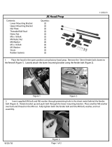
Preparing for Installation
□ Check for RE-VOLT system connected to main power harness. Disconnect if possible.
o Use a multi-meter to check for power on red battery wires after disconnection.
□ Disconnect both batteries, (second one under driver’s door, mounted to frame or other
location), clean off any dirt, dust or debris from air intake tube and air filter box areas.
□ Loosen hose clamps and remove both rubber elbows and intake tube between air filter box
lid and the rubber bellows leading to the engine.
Existing parts may differ slightly from that shown above.
Ensure no dirt or debris enters rubber bellows or air filter box openings.

Air Box Lid Removal
□ Disconnect MAF Sensor.
□ Remove Air Filter box lid, and filter element.
□ Remove the MAF sensor and the filter minder from the lid, and set aside for re-use.
Compressor Remote Air Filter Removal
□ Undo fasteners holding remote air filter mount to radiator support frame. Remove air filter
mount and reinstall fasteners on radiator support frame.
□ Undo hose clamp holding the remote air filter hose to the inlet valve.
□ Remove and discard hose.
Lower Air Box Removal
□ Remove fastener at left front of air filter box where the 1/2" compressor hose is held to the
air filter box with a ‘p-clip’.
□ Remove nut, in bottom of air filter box and lift out filter box.
□ Remove rubber intake sleeve from front of air box. Keep the sleeve, as it will be used with the
modified air box. Do not reuse if it has been modified.
Rubber Sleeve
□ Remove foam piece from rear bottom of air box and save for reuse later.
□ Remove fastener holding rear air filter box support bracket (1200604) to inner fender and
discard, if not previously removed.

□ Remove OEM steel support bracket which had been locating the air filter box, if not
previously removed. See below.
□ Cut off plastic tab from wiring guide that is clipped into fender frame on passenger side of truck.
Remove Air Dam
□ Remove OEM air dam.
Remove OEM air duct
for modification
Air Dam

!
Remove Glow Plug Relay Module
□ Remove plastic inner fender. (OPTIONAL)
□ Undo battery terminals on glow plug module bracket and remove fuse block from bracket.
□ Remove fasteners holding glow plug module bracket to inner fender, firewall and in wheel-
well.
□ Undo fasteners holding the glow plug module on bracket, and remove all battery terminal
posts and plugs. Battery posts will not be re-used.
□ Modify both OEM battery cable ends (positive and negative) by removing the threaded
stud from the battery cable ends and then enlarging the stud holes to allow them to fit
over each of the studs on the glow plug module. The clamping portion of the battery cable
ends can also be cut off as shown below.
Use caution when modifying the battery cable ends. Use a vice or other
means to hold and support the cable end when drilling. A ‘step drill’ is
recommended.

□ If the battery cable clamping portions are not cut off it will look like the image below. Be sure
to wrap any exposed ‘positive’ clamp with black electrical tape to prevent short circuiting.
Inlet Valve Removal and Modification
□ Undo fasteners holding inlet valve on compressor and connecting the two brace parts.
It is very important to tape or cover the opening in the top of the compressor to ensure
that nothing can enter the compressor housing as this may cause severe damage to the
internal parts or failure of the compressor.
□ Remove inlet valve with top brace.

Modify Inlet Valve
□ Remove fasteners retaining the remote air filter plate from the inlet valve.
WARNING – THESE SCREWS ARE TYPICALLY LOCTITED AND MAY REQUIRE
HEATING TO LOOSEN THEM!
□ Install the supplied vertical air filter mounting plate, supplied O-ring and fasteners, and
then install the air filter, cover and nylock nut with flat washer, (see diagram below).
□ If the 3/16” push-to-connect fitting in the inlet valve is a straight fitting, then remove the
fitting and replace it with the supplied 3/16” 90 degree push-to-connect fitting. See below.
□ Rotate the 90 degree push to connect fitting for the scavenge line so that it is pointing
directly down. The replacement scavenge line is longer and will be routed to the outside of
the inlet brace brackets.
O-ring 5830070
Mounting Plate 3200205
Nut 1550221 Threaded Rod 1500519
Air Filter 3600037
Cover 3600066
Washer 1570038
Nylock nut 1550029
Fasteners
Inlet Body for Ref.
This should be a 90 degree fitting
(Note orientation)
!
3200268
Note Orientation

Inlet Brace Replacement
□ Remove the existing brace on the front of the EGR.
□ Replace with the supplied thicker brace. (Figure 3.14), (use supplied M6 bolts, use Loctite and
torque to specifications).
Figure 3.14
Reinstall Inlet Valve
□ Install inlet valve adapter plate onto compressor. See below.
□ Remove the existing brace on the inlet valve and replace with the supplied one.
Lower portion of inlet brace bolts here.
COPPER WASHER

□ Replace inlet valve. Install fasteners finger tight only. (Do not use Loctite on these four (4) bolts).
It must be noted that this system uses three different length bolts in the inlet valves. The
longest bolts go in the two holes closest to the engine (through the bracket) and the shortest
bolt goes in the hole on the passenger side closest to the front of the truck.
Never use an impact wrench to install inlet bolts.
The torque spec for inlet bolts is 19 ft. lbs.
□ Join the brace on the EGR to the one on the inlet valve using the supplied M8 bolts, washers and
nylock nuts. Tighten until the brace and bracket are touching but still have some play.
Ensure the brace bracket bolts are not preloaded before tightening the inlet valve bolts.
□ Tighten all four (4) inlet valve bolts and torque to specification.
□ Tighten the two fasteners joining the brace together and torque to specification (19 ft.lbs).
□ Route the longer replacement scavenge line from the tank up to the engine side of the compressor.
Run the line on the outside of the brace bracket (towards the engine) and connect it to the 90
degree fitting pointing straight down.
!
Longest Bolts
Shortest Bolt

Clutch Guard Replacement and New P-clip on Compressor
□ Undo the two nuts retaining clutch guard at clutch pulley, remove clutch guard. Retain nuts
and flat washers for re-use.
□ Install new clutch guard with rubber pad.
□ Review the routing of the 1/2” hose on the compressor. The hose will route up over the
compressor behind the clutch guard and through the new P-Clip supplied in the retrofit kit.
This hose must be protected from damage from any fasteners or other sharp edges.
□ Finish installing the p-clip and clutch guard using the two nuts and flat washers and ensure the
clutch wire bracket does not twist out of position during tightening.
ADD P-CLIP

Glow Plug Relay Assy, Lower Hood Strut, and Battery Cable Modifications
□ Using a hammer, flatten the sheet metal, raised edge around the lower hood strut area.
□ Ensure there are no sharp edges remaining.
□ Remove countersunk fastener holding long leg of the glow plug bracket to inner fender.
□ Align UHMW pad, supplied, with these two holes in inner fender and the large portion of pad
forward of holes. Reinstall glow plug bracket flathead fastener.
□ Install lower hood strut bracket with supplied fasteners.
Sheetmetal edge
to be flattened
Lower Hood Strut
Relocating Bracket
M8 x 16 Hexhead Bolt
M8 x 20 Flathead Bolt
New Glow Plug Module
UHMW Guard Pad Flathead Fastener
Fastener from underside of plastic inner fender Nut to attach to stud on firewall
Flatten front and bottom edge of
sheetmetal for UHMW pad and glow
plug bracket to sit flush with
sheetmetal.

Upper Hood Strut Relocation
□ Remove hood strut ball stud from passenger side of hood and install into strut relocating
bracket. Install relocating bracket with supplied fasteners as shown. Note the 8mm hex nut
may need to be oriented to fit in the slot in hood.
□ Reinstall passenger side hood strut.
M8 nut
M8 x 18mm bolts
Relocation Bracket

Install Glow Plug Relay Module
□ Install supplied glow plug module bracket, reinstalling parts removed previously in reverse
order.
□ Align UHMW pad, supplied, with these two holes in inner fender, (one where the hood
strut ball stud was located and the second where the glow plug module bracket mounts),
and the large portion of pad forward of holes. See below.
□ Install supplied flathead fastener to hold the glow plug module bracket through the hole in
the bracket and through the lower hole of the UHMW pad and into the inner fender
threaded hole. See below.
□ Reinstall the nut holding the glow plug module bracket to the stud on the firewall. See
below.
Lower Hood Strut
Relocating Bracket
M8 x 16 Hexhead Bolt
M8 x 20 Flathead Bolt
New Glow Plug Module
UHMW Guard Pad Flathead Fastener
Fastener from underside of plastic inner fender Nut to attach to stud on firewall

Install Intake Tube Brace
□ Remove OEM fastener holding ground-strap to firewall as shown, (see below).
□ Use the OEM fastener to tap threads into the existing OEM hole 1-3/4” above the ground-
strap hole. Remove OEM fastener and retain. (6mm tap may also be used).
□ Install supplied brace and ground strap using OEM fastener into lower hole and then the
supplied fastener into the new threaded hole above it. The brace should sit flush against
the firewall with the ground strap on top of the brace. Ensure the brace does not make
contact with the electrical connector on the firewall, (see below).
Tap this hole using OEM fastener Remove OEM fastener from this ground strap

Install Lower Air Box
□ Install rubber intake sleeve previously removed from air box into opening in front of metal
filter box. Groove in rubber fits in opening and rubber tab clips into holes in the front of the
filter box.
□ Install the modified air dam supplied.

□ Insert modified foam filter section into rear of supplied filter box. Foam goes in original
location of plastic section (groove fits in plastic lip).
Install New Lower Air Box Assembly
□ Install supplied air filter box assembly. Rubber at front of air box should fit over the air dam at
the radiator support frame, and the air filter box should be further forward from original
position.
□ Install supplied bolt from inside the lower air box through a clearance hole in the plastic into
the hole in the metal tab and into the forward OEM threaded hole in inner fender. See below.
□ Install supplied bolt through the air box bracket, into second OEM threaded hole in inner
fender, towards rear of air filter box. See below.

Reinstall the Air Box Lid Assembly
□ Re-install the filter minder on the air box lid assembly, use the supplied hose clamp.
□ Install MAF (mass air flow) sensor onto supplied air box lid assembly.
□ Install P-Clip to hold oil line going to cooler and use supplied M8 bolt to go through P-Clip. See
previous page.
□ Install OEM air filter.
□ Fit the air box lid loosely in the silicon elbow included with the intake tube.
□ With the air filter installed, fit the lid securely onto the air box, securing it with the four air box
clips.
MAF sensor

□ Fit the free end of the intake tube loosely into the inlet bellows on the engine.
□ Position intake tube for best clearance to brace. See below.
Intake tube must be positioned as far from the intake tube brace and the firewall
connector as possible before tightening the T-clamps.
□ Before tightening the clamps, make sure the silicon elbow is positioned to provide an adequate
sealing surface under each clamp. Align the clamps with the edges of the silicon elbow.
To seal properly, the clamps require a sealing surface which is, at minimum, as wide as the
clamp strap.
Intake Tube Brace
Should Be Clearance Here Should Be Clearance Here .
!
!

Ensure intake tube is close to, and or resting on the clutch guard rubber pad.
Loosen hose clamps and adjust tube position if required.
□ Check hood clearance to intake tube and adjust tube into rubber elbow if required.
□ Tighten the clamps, making sure they seal completely. Do not use an impact driver, as this may
damage the air box lid.
□ Add ‘paint pen’ or other marker to indicate proper alignment once final position is set.
□ Plug in the MAF sensor connector.
□ When the position of the intake system is finalized, ensure all the clamps are tight and apply
the supplied heat shrink to the two T-bolt clamps.
The T-bolt clamps should never be removed when servicing the air filter.
For more information regarding these changes please contact VMAC Tech Support 1-888-241-2289
Changes and Revisions
Version
Revision Details
Revised by/date
Reviewed by/date
Implemented
A
ECN 13-075 Engineering Release
SM 13 Sep 2013
RD 13 Sep 2013
13 Sep 2013
B
ECN 13-082
SM 18 Sep 2013
MH 24 Sep 2013
24 Sep 2013
C
ECN 13-102
CJH 07 Nov 2013
MH/DB 07 Nov 13
07 Nov 2013
!
!
/