Page is loading ...

Operator‘s manual
Translation of the original Operating Manual
Nr. 99+476.EN.80R.1
Forage harvester
MEX 6
(Type 476 : + . . 01001)
(Type 477 : + . . 01001)

Your Machine Identification No.
Forage harvester
MEX 6
(Type 48830071+48830046/7
– Corn)
(Type 48830090/5+48830011
– Grass)
Instruction Manual No. 001/201
7

Index page
Meaning of the warning signs
Putting into use
Putting into Use (general safety tips)
Opening of the blades disc lid
Travelling on public routes
Before
starting work
Checks before use
Definition of the use of the machine
Correct loading
Location of the machine identification and its composition
The most important components of the machine
Technical information
First connection to the tractor
Hydraulic con
nection
Regulation of the hydraulic block
Connection of the hydraulic hoses/power source
Initial connection to the tractor (command functions)
Coupling the machine to the tractor
Metal detector
Regulation/tuning
Adjusting the height of work/transport
Regul
ation of the drawbar for work/transport
Tuning of the work speed
Adjusting the length of the cut
Alteration of speed of the feed rollers
Assembly or removal of the blades
- tuning
Transport by road/safety devices
Transport by road
How to fold with the pipe
Fitting the safety devices
Operating in a field
How to place the pipe in the working position
Working recommendations
Regulation of the upper flap movement
Operating with 4
-line head for corn
Pipe blockage
4
5
5/6
6
7
7/8
9
10/11
12
13/14/15
16
17
17
18
19
20/21
22/23
24/25
26
27
28
29
29
30
30/31
32/33
34
35
35
37/38/38/39
39

How to switch off the machine
Cleaning
Assembly of the corn head
Assembly of the grass pickup
Adjusting and tuning the corn head
Maintenance and repairs
Maintenance and Repairs
Changing the pulleys
Sharpening the blades
Adjusting the sharpening disc
Sharpening procedure
Adjusting the blades disc
Replacement of the blades and counter-blade
Installation of the corn chopper kit
Maintenance care (oil levels/winter storage)
Tuning the currents of the corn head
Clutch of the corn head (tuning)
Tuning the belts of the lateral spindles
Maintenance of the grass pickup (Lubrication/Tuning of the chains)
General lubrication
Breakdowns and possible solutions.
Possible breakdowns and their solutions
Breakdowns and solutions for electrical faults
Hydraulic scheme of the functioning of the machine
Cardans
P.T.O. transmission cardan application options
P.T.O. transmission cardan (application and maintenance)
40
40
41/42/43/44/45
46/47/48
49
50/51
52
53
54
55
55/56
65/57/58
58/59
60/61
61/62
62/63
63
64/65
66/67/68/69
70/71
72
73
74
75

4
MEANING OF THE WARNING SIGNS
Switch off the motor and remove
the key before carrying out
maintenance and repairs
Keep the hands away from the crushing area while
there is a chance that the respective parts are in
motion
Keep away from the vertical displacement
area of the tractor's three
-point hydraulic
system
Wait for a complete stop of all of the
machine's moving parts before touching
them.
Do not open or remove the covers from gears,
roller chains and belts, while these are moving
Install the protection cover before sharpening
the blades
Keep a safety distance from the
machine - danger of projection
Keep away from the
articulation area of the machine
-
danger of pinching/crushing
Keep away - danger
rolling/dismembering/
crushi
ng
Avoid the collision with electrical
cables, danger of electric
shock/electrocution
Do not climb on the machine whenever
there are moving components, danger
of dragging
Rotating blades, danger of cutting,
perforation or crushing
to the hands or feet
Do not stay on the platform or
stair while the machine is being
displaced

5
PUTTING INTO USE
General safety tips for the use of the machine
Tips for manoeuvres with the machine
There is a danger of overturning when you work on slopes.
Driving should be adapted to the terrain and ground conditions.
The tractor vehicle should be equipped in a sufficient form with
weights at the front or at the back in order to guarantee the capacity
to drive and brake (a minimum of 20% of the tare weight of the
vehicle on the forward axle).
Transporting people on the machine is not permitted.
Tips for coupling and uncoupling
There is a risk of injury when you
couple the device to the tractor!
While the machine is moving backwards, do not pass between it and
the trailer during the coupling.
It is strictly prohibited to place yourself between the tractor and the
machine if these have not been totally immobilised with a parking
brake and/or blocks on the wheels.
The coupling or uncoupling of the transmission cardan should only be
undertaken when the motor has stopped.
Take care when opening the lid of the blades disc!
For the purposes of maintenance, the lid
of the blades disc
must be opened regularly.
After stopping the P.T.O. of the tractor, remove the transmission cardan,
there is risk of injury if the P.T.O. is started up accidentally.
Opening of the blades disc lid
The blades disc lid is equipped with
a safety system that prevents it from opening unless the blades disc
has completely stopped. It operates as follows:
Press the green button (2) to unlock the door (1). If the orange light (3) goes on, this means the blades
disc is still in motion
(sensor 4 is still detecting motion) and the system is still preventing the lid from
opening. If the green light (5) also goes on, this means the disc is already stopped; it will blink for 5
seconds until it goes on permanently, indicating the system is unlocked
, and allowing you to open the
door (1) by pulling handle (6). After 15 seconds, the system locks again. If the door (1) is still closed,
press the green button again.
4

6
While the door (1) is open, or if it is not properly closed, ligh
t (7) remains on.
In case of electrical malfunction or in the absence of electric power supply (maintenance/storage) the
system stays locked; to unlock it, use key (8), supplied with the machine, and turn it to UNLOCK.
After repairing the malfunction or af
ter making the electrical connection to the tractor, lock the system
again by turning the key to LOCK; if you forget to do so, the light will stay on, turning off as soon as you
turn the key to LOCK.
Remove the key and keep it together with your tractor's
key.
Parking/storing the equipment:
When the equipment is parked, remove the transmission cardan and store it or secure it with a chain.
Only use the machine in accordance with the regulations!
Usage Regulations:
- See "Technical Information" Chapter.
- See "Definition of use of the machine" Chapter.
The load limits of the machine may not be exceeded.
Additionally, comply with the power limits of the tractor to be used.
Travelling on public routes
-
Comply with the traffic rules in force.
-
Lighting devices should be installed, applied perpendicular to the route.
-
Pay attention to the total height of the machine, it must not exceed 4 m from the ground; for this, use
the hydraulic articulation of the discharge pipe (see chap
ter “how to fold down the pipe”)
-
Pay attention to the additional length of the machine.
-
Total length of the machine in transport:
-3.14 m - with the corn cutter and collector head
- 2.90 m- with the grass pickup of 1.90 m.

7
PUTTING INTO USE
Before starting work
a. Before starting work, the operator should have knowledge about all of the functioning devices
and their functions. It is too late to learn these aspects if work has already begun!
b. The machine should be tested for safety in travelling and functioning before each operation.
c. There is a danger of crushing or dismembering in the areas of the pickup, cutting unit, rear lid
and higher extension zones. Everyone should stand well back from these areas before the
hydraulic equipment and the transmission are switched on.
d. Before driving the vehicle, the driver should ensure that no one is in danger and that there
are no obstructions. If the driver is not able to see and to have a general view of the road
directly behind the machine, he should be helped by somebody during manoeuvres in
reverse.
e. Comply with the safety tips in relation to the machine. You may find an explanation of the
meaning of the graphic warning symbols on page 4.
f. Comply also with the tips in the relevant chapters and in the supplement to this functioning
manual.
g. Check the hydraulic hoses regularly and replace old and damaged hydraulic hoses. The
replacement hoses should comply with the technical requirements of the manufacturer.
h. For all maintenance, service and modification works, switch off the transmission motor and
remove the universal transmission.
Check before use
The following tips should make the operation of the machine simpler for you. You
may find detailed information on specific points in the relevant chapters of this
instruction manual.
1. Check that all of the safety equipment (covers, shields, etc.) is in good condition and installed
in the correct position.
2. Lubricate the machine in accordance with the lubrication scheme. Check the oil levels.
3. Check if the tyres have the correct air pressure.
4. Check if the wheel nuts are tightened firmly.
5. Check the correct rpm of the P.T.O.
6. Carry out the electrical connections to the tractor and check whether they are correct. Take
note of the tips in the instruction manual!
7. Carry out the following adaptations:
- Height of the drawbar
- Positioning of the electrical cables
- Transmission axle
8. Affix the machine using only the fittings supplied.
9. Cut the transmission cardan at the correct length and check the functioning of the free wheel.
(see page 67).

8
10. Check the functioning of the electric controls.
11. Connect the hydraulic hoses to the tractor.
- Check the hydraulic hoses against the existence of damages and wear and tear.
- Certify that the connections are correct.

9
Definition of the use of the machine
The machine “MEX 6 ” is designed only for normal use in agricultural work.
Corn cutting, collecting and milling machine: For the harvesting of silage corn
Machine for collecting and cutting green forage (grass): For collecting and cutting grass
Any other use apart from this is held as inadequate. The manufacturer does not bear any
responsibility for any damage that results from this. The risk is borne only by the user.
The maintenance of the functioning, service and maintenance requirements stipulated by the
manufacturer is also under the designation of "defined use".
Safety tips
1. Connect the P.T.O.
Connect the P.T.O. o
nly when all of the safety devices (covers,
protective aprons, coatings, etc.) are in good conditions and are affixed
to the device in the correct protective positions.
2.
Connect the machine only in the working position and do not
exceed the prescribed start-
up speed (for example, max. 1000
rpm).
A sticker located close to the gears will advise you on the speed for
which the machine is equipped.
3.
Pay attention to the correct rotation direction of the P.T.O.!
4.
Use ear protection
- The noise level at
the place of work could differ from the measured
values (see Technical Information) in part due to the different types of
cabins in various tractors.
-
If the noise level of 85 dB (A) is reached or exceeded, the farmer
should have adequate ear protection available.
Safety indication
for the supplementary installation of electrical and electronic installations
and/or components
- See supplement

10
Correct loading:
To load the Mex6 correctly, it is recommended to use:
1x-Belt with ±3 m.
2x-Belt with ±1 m.
1x-Set of 3 belts or chains, with suspension shackles.
1st-Position the 1 m belts around the axles and place the loops in the shackles.
2nd-Apply a protection in the belt/lock, to protect the machine's paintwork.
3rd-Place the folded 3 m belt in the front coupling and position the loop in the shackle.

11
4th-Position the machine in the truck's platform, with the drawbar to the front. If possible, it
should be positioned at an angle to the platform, so that it does not move during transportation.
Note: It is very important the loading is carried out as recommended; the company
declines all responsibility for any damage during unloading.

12
POSITION OF THE SERIAL NUMBER/FRAMEWORK OF THE MACHINE AND
IDENTIFICATION OF THE BASE DEVICE AND THE ACCESSORIES
The serial number of the machine is engraved on the plaque presented
and also on the structure.
The requests for activation of the guarantee and questions shall not be
dealt with if this number is not supplied.
Please write the number on the first page of the instructions manual
immediately after receiving the vehicle/machine.
TOWED VERSION MEX 6-CORN----
OR
TOWED VERSION MEX 6
-GRASS-----
3 or 4
-LINE HEAD FOR CORN---
(WIDTH OF CUT: 2.00 or 2.35 m)
GRASS PICKUP
(width of collection X=1900 mm)

13
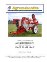
THE MOST IMPORTANT COMPONENTS
1 = Collection drums (corn)
2 = Front guide nozzles (corn)
3 = Spindles for collecting fallen corn (corn)
4 = Upper guide (corn)
5 = Hydraulic cylinder for regulating the height of the cut (corn)
6 = Stoppers for regulating the height of the cut (corn)
7 = Coupling to the tractor
8 = Drawbar
9 = Protection of the front nozzles
10 = Control box for the machine functions
10A= Joystick to control pipe rotation and flap articulation.
11 = Pipe support
12 = Mechanical support on the ground
13 = Pipe support tensioners
14 = Blades disc lid
15 = System for sharpening the blades
16 = System for rotating the pipe
17 = Hydraulic block
18 = Rear indicators
19 = Pipe articulation cylinder
20 = Ejector pipe
21 = Flap regulating cylinder
22 = Pipe extension L=1.8 m. (corn)
22A= Pipe extension W=1.00 m. (grass)
22B= Pipe extension W=1.40 m. (option)
23 = Discharge nozzle
24 = Pipe articulation with vertical extension of 0.70 m. (corn)
24A= Pipe articulation with vertical extension of 0.50 m. (grass)
25 = Collecting and milling unit
26 = Hydraulic hoses for connecting to the tractor
27 = P.T.O. cardan 1 3/8” 6 ridges
27A = P.T.O. cardan 1 3/8” 21 ridges
27B = P.T.O. cardan 8x32x36
28 = Transport wheels with hydraulic regulation (corn)
28A = Fixed transportation wheels (grass)
29 = Control box for the metal detector (option)
30 = Blades disc
31 = Lower intake rollers
32 = Upper intake rollers
33 = Corn chopping system (corn)

14
34 = Rear lights (optional)
35 = Pickup drum (grass)
36 = Deflector (grass)
37 = Security tube (grass)
38 = Auger (grass)
39 = Support wheel (grass)
40 = Safety device (grass)
41 = Rear coupling for trailer
42 = Towing eye 50mm (optional)

15
30
31
33
32
25
34
40
39
35
36
38
37
41
42

16
Technical information
(Subject to modification for the purposes of technical development)
Power requirements:
3
-line head for corn:
Pickup
P.T.O. rotation
Diameter of the blades disc
Opening for forage
Number of blades
Permanent level of sound emission
Weights:
Mex6 machine with discharge pipe
Accessories:
3-line head for corn:
Pickup 1.90 m
Dimensions
:
Mex6 machine (for corn or grass)
Length
Width
Height with extension of 0.5 m at work
Height with extension of 0.7 m at work
Height with extension of 0.5 m at transport
Height with extension of 0.7 m a
t transport
of 96 KW (130 HP)
of 74 KW (100 HP)
1000 rpm
1220 mm
800 cm
max. 10
89.2 dB(A)
approx. 2100 kg
approx. 850 kg
Approx. 510 kg
4.99 m (corn)
-4.72 m (grass)
3.14 m (corn)
-3.01 m (grass)
4.56 m
4.76 m
2.70 m
3.20 m
Load capacity in rear coupling:
Model
Vertical load (max.)
Towable load (max.)
40 km/h
25 km/h
40 km/h
25 km/h
Grass
2350 kg
2500 kg
12000 kg
16000 kg
Corn
2000 kg
2500 kg
12000 kg
16000 kg
Necessary plugs
1 double-effect hydraulic plug
min. pressure.: 140 bar
max. pressure.: 180 bar
1 plug with 7 pins for lighting (12 volt)
1 plug with 3 pins (12 volt) (see appendix)
Tyres
Application
Max. pressure
(bar)
Tightening torque
(Nm)
L.I.
(Kg)
S.I.
Km/h
340/55-16
Mex 6
4,0
320
140 (2500 kg)
A8 (40 km/h)
13x5.00-6
Grass
pickup
2,5
------
52 (200 kg)
A6 (30 km/h)
Optional equipment:
- Horizontal extension of the pipe (1.0/1.40/1.80 m)
- Vertical extension of the pipe (0.5/0.7 m.)
- Metal detector
- Electrical installation for travelling on public routes
- Transmission cardan in accordance with the P.T.O. of the tractor
- Load sensing system
- Rear coupling for trailer
All of the information is subject to revision.

17
FIRST CONNECTION TO THE TRACTOR
HYDRAULIC CONNECTION
VERY IMPORTANT: Before making the hydraulic
connection to the tractor, check the oil condition. If it
is contaminated, change it, otherwise the hydraulic
block and remaining hydraulic components of your
machine could be damaged.
The machine needs 1 double hydraulic circuit,
to
activate the hydraulic block
, in order to do this:
-
Connect the pressure line (1) and the oil return tube (2) (the
tube with the bigger diameter is the oil return tube), the
command lever of the line on the tractor has to be positioned so
that the hose of the greatest diameter is m
aking the return to
the tank.
Note:
If the oil heats up during functioning, and the tractor only has a
constant flow rate pump, then it should be linked to a
simple effect line (see image).
- Connect the pressure hose (1) to the single action control unit
.
Connect the oil return hose (2) (with the bigger diameter) to a
direct connection to the oil deposit.
If the tractor allows it, reduce the oil flow rate
REGULATION OF THE HYDRAULIC BLOCK:
Pos. "H±10 mm" to closed hydraulic system
Tractor with variab
le flow rate pump
Before making the connection, the LS screw on the hydraulic
block should be adjusted to the quota of ±10 mm (totally fasten
LS)
Pos. "H±17 mm" to open hydraulic system
Tractor with constant flow rate pump
The position of the LS screw on the hydraulic block should be
adjusted to a quota of ± 17 mm. (totally unfasten LS)- (factory
configuration).
Warning!
If this is not done, the overload valve on the hydraulic system of
the tractor is continuously in use and an excessive heating of the
oil will take place.
If the tractor has a
closed
hydraulic system and the hydraulic block
is in the position "A=17" then the hydraulic oil will heat up
(especially due to the constant pumping of the maximum quantity
of oil).
Solution
: Place the tuner LS on pos. “A=10 mm”
LS = Load detection
LS
A

18
P
Ls
R
FIRST CONNECTION TO THE TRACTOR
Connection of the hydraulic hoses, for tractors with
fixed flow rate pump.
-
Disconnect the P.T.O. before making the connection
-
Place the lever (ST) of the control unit in th
e fluctuating position
(neutral position),
-
Ensure that the rapid valves are clean.
-
Make the hydraulic connection of the hydraulic block. A double effect
-
Check if the hose of the smaller diameter is the one with pressure.
Connection of the hydraulic hoses, for tractors
with variable flow rate pump.
-
Disconnect the P.T.O. before making the connection
-
Connect the return hose (larger diameter-3/4”) to valve
(R), the pressure hose (1/2”) to valve (P) and, finally, the
smaller diameter hose (1/4”) to
valve (LS).
Power source
Necessary connections to the tractor
3
-prong current plug
-
Connect the attached 3-prong plug to the rear of the tractor
-
Power source through a relay (9)
The relay is connected to the ignition switch (10).
-
The diameter of the conductor is at least 4 mm2
-
Fuse 16A (11)
You may find a complete diagram of the electrical connections on the list of spare parts.
This connection may only be made by a specialist
Do not connect directly to the ignition switch
- There is a risk of fire or damage to the electrical unit.
• Use only fuses at the recommended power as the use of stronger fuses will destroy
the electrical unit!
Establish the connection with the tractor
-
After concluding the work as demonstrated, connect the three-pin
jack to the tractor power socket.
-
Check if the lights on the command panel (13) are working
-
Install the command (magnetic base) in the interior of the tractor in
an
accessible (metallic) place with good visibility.
13

19
INITIAL CONNECTION TO THE TRACTOR
-
Switch the lever (ST) to the "ON" position and affix it.
Check if the hose of the smaller diameter is the one with
pressure, otherwise reverse the connection of the hoses or
reverse the position of the ST lever, affixing it again.
-
The system is protected with a 15A fuse on the power jack
of the command (5)
Explanation of the command functions
A
= This button has two functions: When it is continuously
pressed, it switches on and off the command, when it is
pressed with one simple touch it commutes the functions in
accordance with the colour of the bulb (green or red)
B1/C1 (red)
= Executes function 1
for orientation of the
discharge nozzle
D1/E1 (red)
= Executes function 2
for the rotation of the
discharge pipe
F/G (red)=
Executes function 3
of coming closer/ /moving
away from the ground of the corn/grass cutting head and
simultaneously raises/lowers the transport wheels
8
(only
corn version), this button also executes the activating
function of
the skid
5 for assisting assemb
ly/disassembly of the grass
pickup, whereby you just need to connect the respective rapid
valve to the hydraulic block of the machine.
H (red) =
Executes function 6
which reverses the rotation of
the head and the feed rollers, whereby you just need to press
the button. When you stop pressing, the direction of rotation
returns to the initial one.
B2/C2 (green
) = Executes function 7
for positioning the
drawbar: transport/work
D2/E2 (green) =
Executes function 4
for the articulation of
the discharge pipe
5
1
3
2
4
5
6
8
Light for
Indicating the
command
green/red
B2
C1
C2
G
B1
H
D1
E1
E2
D2
A
A
F
D1
E1
B1
C1
7
/