- 3 -
M965941 (8/18)
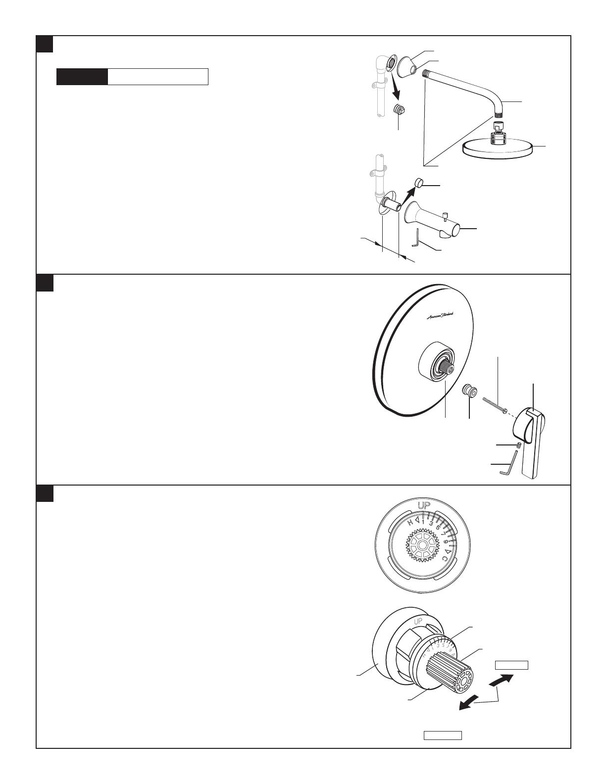
3
INSTALL, TUB SPOUT, SHOWER HEAD,
SHOWER ARM WITH FLANGE
Note: Apply sealant or Teon Tape to shower arm.
• Remove PIPE PLUG and CAP (1, 2) from shower pipe
and tub ller pipe.
• Install SHOWER ESCUTCHEON (3) onto SHOWER
ARM (4). Apply sealant or Teon tape to threads on
both ends of SHOWER ARM (4) and thread longer
leg of SHOWER ARM (4) into shower elbow.
Thread SHOWER HEAD (5) onto SHOWER ARM (4).
• Install SLIP-ON TUB SPOUT (6). Tighten with
HEX WRENCH supplied.
Important: Do not overtighten Set Screw.
CAUTION
Protect finish on SHOWER HEAD
and TUB SPOUT when installing.
5
4
• By restricting HANDLE rotation and limiting the amount of hot water
allowed to mix with the cold, the HOT LIMIT SAFETY STOP (1)
reduces risk of accidental scalding. To set the maximum hot water
temperature of your faucet valve, adjust the setting on the HOT LIMIT
SAFETY STOP (1).
• Turn CARTRIDGE STEM (2) to the OFF position (coldest setting) before
making adjustment to HOT LIMIT STOP (1). Pull forward and rotate
counterclockwise one number to limit hot water temperature.
Use NUMBERS (3) on CARTRIDGE (4) on HOT LIMIT STOP (1)
for indication.
• Hold ADAPTER (1) onto VALVE STEM (2) and install
ADAPTER SCREW (3) through ADAPTER (1) into
VALVE STEM (2).Tighten ADAPTER SCREW (3) to
secure ADAPTER (1) to VALVE STEM (2).
• Install HANDLE BASE (4) onto ADAPTER (1). Insert
SET SCREW (5) into HANDLE BASE (4). Align
HANDLE BASE (4) and tighten with HEX
WRENCH (6) supplied.
ADJUST HOT LIMIT STOP
INSTALL HANDLE
COLDER
(Larger Numbers)
1 2 3 4 5 6 7 8 9 10
HOTTER
(Smaller Numbers)
1 2 3 4 5 6 7 8 9 10
3
4
1
5
2
5
2
6
4
APPLY SEALANT OR
TEFLON TAPE TO THREADS
O-RING
HEX WRENCH
1-3/4"
(44 mm)
1
3
1
5
2
6
4
H
C
OFF


