
Wiremold / Legrand electrical systems conform to and should be
properly grounded in compliance with requirements of the current
National Electrical Code or codes administered by local authorities.
All electrical products may present a possible shock or fire
hazard if improperly installed or used. Wiremold / Legrand electrical
products may bear the mark as UL Listed and/or Classified and should
be installed in conformance with current local and/or the National
Electrical Code.
24R Plugmold
®
INSTALLATION INSTRUCTIONS
Installation Instruction No.: 1 007 574 – February 2008
IMPORTANT: Please read all instructions
before beginning.
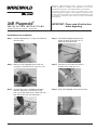
BACKFEEDING 24R PLUGMOLD
Step 1 Remove appropriate 1/2" trade size knockout
from the base.
Step 2 Feed cable through connector and
attach the base to the 2451 or 1/2"
trade size feed connector.
Step 3 Mount the 24R Plugmold base to the wall
using No. 8 flat head screws every 32" max.
Step 4 Cap wires at the end of the harness
on both sides using wire nuts.
Step 5 Cut and strip wires in appropriate location.
Connect feed wires to the harness using
wire nuts or W30 Connectors. (Wire Nuts and
W30 Connectors are sold separately.)
Step 6 Snap 24R Plugmold cover onto the base.

Wiremold / Legrand
U.S. and International:
60 Woodlawn Street • West Hartford, CT 06110
1-800-621-0049 • FAX 860-232-2062 • Outside U.S.: 860-233-6251
Canada:
570 Applewood Crescent • Vaughan, Ontario L4K 4B4
1-800-723-5175 • FAX 905-738-9721
© Copyright 2008 Wiremold / Legrand All Rights Reserved
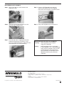
END FEEDING 24R PLUGMOLD
Step 1 Mount 2400 box or 2410C entrance end
fitting to the wall.
Step 2 Connect 24R Plugmold base to box or
entrance end. Mount the 24R Plugmold
base to the wall using No. 8 flat head screws.
Step 3 Cap wire at the end of the harness on the
non-feed side using wire nuts.
Step 4 Snap 24R Plugmold cover onto the base.
Step 5 Cut and strip wires in appropriate location.
Connect feed wires to the harness using
wire nuts or W30 Connectors. (Wire Nuts and
W30 Connectors are sold separately.)
COUPLING AND CUTTING 24R PLUGMOLD
Coupling – 24R Plugmold may be coupled
using 2401 Couplings.
Cutting – 24R Plugmold may be cut to length.
If 24R Plugmold is cut a 2409 grounding
clamp must be installed in each section
of 24R Plugmold. 24R Plugmold has
one 2409 factory installed per section.
Additional 2409 may be purchased
separately.
1 007 574 0208
-
 1
1
-
 2
2


Legrand 24R Series Plugmold Multioutlet System Installation guide
- Type
- Installation guide
- This manual is also suitable for
Ask a question and I''ll find the answer in the document
Finding information in a document is now easier with AI
Related papers
-
Legrand TableSource Work Surface Modules Installation guide
-
-
Legrand PM48TC User manual
-
-
-
-
-
-
-
Legrand PM22WH Installation guide
Other documents
-
Novus Pura Line Multipupose Box Datasheet
-
Legrand Wiremold C40 Specification
-
Intermetro PS36 Datasheet
-
-
-
Buderus 600-11R Installation And Servicing Instructions
-
-
Pelco PT573 User manual
-
PRESONUS NSB 8.8 Owner's manual
-
Pitco Frialator 24R-UFM User manual