
User’s Manual
RS SERIES NETWORK RACK
RS47U100/RS47U120
RS22U80/RS42U100/RS42U120/

Before installing this product, please note the following safety information:
1. Always lower the leveling feet of the rack cabinet;
2. Always install equipment starting from the bottom of rack cabinet to top;
3. Always install the heaviest equipment in the bottom of the rack cabinet;
4. Always have two or more persons during assembling and moving the rack cabinet;
CAUTION:
OVERVIEW:
NOTE:Above products can be shipped in Build-up method or Knock-down/at-packed
method
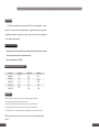
Model No. Capacity(U) Width(mm) Depth(mm)
22U
42U
42U
47U
47U
AVAILABLE RACK DIMENSIONS BELOW:
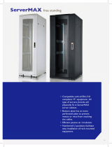
RS SERIES FEATURE:
ATEN Racks are designed for mounting standard 19“ rack - mount equipment – servers,
routers, UPS systems, switches, audio/video devices – regardless of brand. All racks provide
straightforward equipment organization, excellent security and simple cable management
while enabling optimum airflow.
1. Hexagonal perforated front and back doors provide higher tensile strength than round holes
while ensuring efficient airflow and optimized ventilation
2. Static loading capacity up to 800KG
RS22U80
RS42U100
RS42U120
RS47U100
RE47U120
600
600
600
600
600
800
1000
1200
1000
1200

04 01
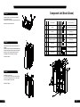
Component List (Knock Down)
REV
1
2
3
4
5
6
7
8
REV
H1
H2
H3
H4
H5
H6
H7
H8
QTY
4
16
16
44
44
18
16
4
QTY
1
2
1
4
4
2
1
1
COMPONENT
BOTTOM TRA
Y
FRAME
TOP TRAY
HORIZONTAL SUPPORT
VERTICAL SUPPORT
SIDE PANEL
REAR DOOR
FRONT DOOR
M12*L90 Leveling Leg
M8*12 Round Head Inner Hex Scew
M8 Flange Nut
M6*12 Screw
M6 Cage Nut
M4*8 Self-tapping Screw
M6*12 Tapping Screw
Side Panel Limit Stop
SCREWS AND NUTS
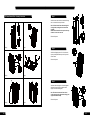
Step 4:
Step 5:
Step 6:
Install the castors to the four corners at bottom by
M6*12 self-tapping screws.
Install the M12*L90 Leveling Legs also to each corner.
Refer the left upward view picture.
Install side panels, adjust the diagonal dimension of
cabinets.
Remark: because the cabinets is disassembled design,
after assemble, please check and adjust the diagonal
dimension, ensure the space between doors are
acceptable, doors could open and close well.
Refer the left picture.
Install front door, rear door.
Put the door block to the hole of the bottom of frame,
and set the front door/rear door. Fix the top of front/
rear door by bolts and top of frame.
Refer the left picture.
01

02
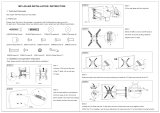
Step 1:
Step 2:
Step 3:
Use M8*12 round head inner hex screws & M8 ange
nuts
to connect the frames, top & bottom.
Note A: Ensure that the frame with earthing kits is
at the right side, earthing kits is at bottom when
assemble.
NoteB: Ensure that the fan-unit at top & cable entry
at bottom is close to the rear side.
Refer the left picture.
Use M4*8 self-tapping screw to x the fan unit to the
top tray and side panel limit stops to the four posts of
the two frames.
Refer the left picture.
Install the horizontal supports to the vertical supports
with M6x12 Screws rst.Then Install the vertical
supports to the horizontal supports.
Note: The distance between the front and rear
vertical supports can be adjusted according to your
equipment installation depth.
Refer the left picture.
03
Step1 Step2
Step3 Step4
Step5 Step6
RS Series Network Rack Assembly Instruciton
-
 1
1
-
 2
2
-
 3
3
-
 4
4


ATEN RS42U120 User manual
- Category
- Rack accessories
- Type
- User manual
Ask a question and I''ll find the answer in the document
Finding information in a document is now easier with AI
Related papers
Other documents
-
APC AR2316BLK Datasheet
-
Lenovo 42U 1200 mm Deep Dynamic Rack Installation guide
-
 Mount Plus 8541750547 User manual
-
 Estap SRV47U80_03M1P_TR Datasheet
-
Legrand LX User guide
-
Digitus DN-19 TRAY-3-47U Datasheet
-
IBM 42U Enterprise Expansion User manual
-
Intellinet 201704 Datasheet
-
Equip 992435 User manual
-

