Page is loading ...

1
Mira Calibre Thermostatic Shower
These instructions must be left with the user
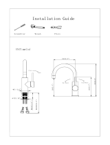
Installation Guide
For SPARES, ADVICE
or REPAIRS
Please call us on
0844 571 5000
(UK Only)

2
If you experience any difficulty with the
installation or operation of your new
thermostatic mixer, please refer to ‘Fault
Diagnosis’ before contacting Mira Showers.
Our contact details can be found on the back
cover of this guide.
CONTENTS
Introduction 3
Guarantee 3
Recommended Usage 3
Patents and Design Registration 3
Safety Warnings 4
Pack Contents 5
Mira Calibre EV 5
Mira Calibre ER 6
Specications 7
Pressures 7
Temperatures 7
Thermostatic Shut-down 7
Connections 7
Dimensions 8
Installation 9
Suitable Plumbing Systems 9
General 9
Mira Calibre EV
Installing the Shower Mixer 10
Installing the Slide Bar
and Shower Handset 14
Mira Calibre ER
Installing the Shower Mixer 16
Installing the Riser Pipe
and Showerhead 20
Commissioning 22
Maximum Temperature Setting 22
Mira Calibre EV 22
Mira Calibre ER 24
Operation 26
Mira Calibre EV 26
Height Adjustment 26
Changing the Spray Setting 27
Mira Calibre ER 28
Showerhead Adjustment 28
User Maintenance 29
Fault Diagnosis 29
Lubricants 29
Cleaning 29
Spray Plate 29
Spare Parts 30
Mira Calibre EV 30
Mira Calibre ER 32
Customer Service 36

3
INTRODUCTION
Thank you for purchasing a quality Mira product.
To enjoy the full potential of your new product,
please take time to read this guide thoroughly,
having done so, keep it handy for future reference.
The Mira Calibre EV is a thermostatic mixing
shower with integral slidebar, hose and Mira 360
shower handset.
The Mira Calibre ER is a thermostatic mixing
shower with integral riser rail and xed height
250mm showerhead attached with a ball joint.
The thermostatic mixing valve incorporates a
temperature sensing unit, which provides an
almost immediate response to changes in water
temperature or pressure to maintain a comfortable
shower. An adjustable maximum temperature stop
is provided to limit the showering temperature to
a preset level. This is a safety feature that can be
adjusted after installation (see “Commissioning”
for further details) Inlet water lters are tted to
protect the internal mechanism.
Products manufactured by us are safe and
risk-free, provided they are installed, used and
maintained in good working order, in accordance
with our instructions and recommendations.
Guarantee
For domestic installations, Mira Showers
guarantee the Mira Calibre Thermostatic Mixer
against any defect in materials or workmanship for
a period of ve years from the date of purchase.
The shower handset, hose and clamp bracket
supplied with the Mira Calibre EV model are
guaranteed for one year from date of purchase.
The showerhead supplied with the Mira Calibre ER
model is guaranteed for one year from date of
purchase.
For terms and conditions refer to ‘Customer
Services’ on the back cover of this guide.
Recommended Usage
Application Valve with Fittings
Domestic
ü
Light Commercial
ü
Heavy Commercial
û
Healthcare
û
Patents and Design Registration
Patents:
GB 2 422 886
Patent Applications:
Europe 07015846.4
USA 2010-0219255-A1
Design Registration:
001240527 - 0002
001240527 - 0004
001312649 - 0014
001004022

4
SAFETY WARNINGS
WARNING - This product can deliver scalding
temperatures if not installed, operated
or maintained in accordance with the
instructions, warnings and cautions contained
in this guide.
The function of a thermostatic mixing valve is to
deliver water consistently at a safe temperature. In
keeping with every other mechanism, it cannot be
considered as functionally infallible and as such,
cannot totally replace a supervisor’s vigilance
where that is necessary. Provided it is installed,
commissioned, operated and maintained within
manufacturers recommendations, the risk
of failure, if not eliminated, is reduced to the
minimum achievable.
Mira thermostatic mixers are precision engineered
and should give continued safe and controlled
performance, provided:
1. They are installed, commissioned, operated
and maintained in accordance with the
manufacturer’s recommendations.
2. Periodic attention is given, when necessary, to
maintain the product in good functional order.
Caution!
1. Read all of these instructions.
2. Retain this guide for later use.
3. Installation must be carried out in accordance
with these instructions, and must be conducted
by designated, qualified and competent
personnel.
4. Provision must be made to prevent water
ingress back into the wall structure.
5. DO NOT fit the product where it may be
exposed to freezing conditions. DO NOT
operate this appliance if it is frozen. Allow the
appliance to thaw and check for leaks before
using.
6. Make sure that any pipework that could
become frozen is properly insulated.
7. DO NOT overtighten grubscrews as product
damage may occur. Use hexagonal key
provided and hand tighten only, DO NOT use
power tools.
8. All pipework must be checked for leaks before
the product installation is completed. The
product should be pressurised and the inlet
and outlet connections inspected.
9. Pass on this guide in the event of change of
ownership of the product.
10. Follow all warnings, cautions and instructions
contained in this guide.
11. Make sure that you fully understand how
to operate this shower before use, read all
operating instructions and retain this guide for
future reference.
12. Care is required when adjusting flow or
temperature. Make sure that the temperature
has stabilised before use.
13. This product is not intended for use by
persons (including children) with reduced
physical, sensory or mental capabilities, or
lack of experience and knowledge, unless
they have been given supervision or instruction
concerning the use of the product by a person
responsible for their safety.
14. Children should be supervised to ensure that
they do not play with the product.
15 . DO NOT perform any unspecied modications
to the shower or its accessories. When
servicing only use genuine Kohler Mira
replacement parts.
16. If the shower is dismantled during installation
or servicing then upon completion the product
must be inspected to ensure all connections
are tight and that there are no leaks.
17.Only Mira recommended outlet ttings should
be used.
18. Sunburn or skin conditions can increase your
sensitivity to hot water. Make sure that you set
the shower to a cooler temperature.
19. The water supplies to this product must be
isolated if the product is not to be used for a
long period of time. If the product or pipework
is at risk of freezing during this period they
should also be drained of water.
20. When this product has reached the end of its
serviceable life, it should be disposed of in a
safe manner, in accordance with current local
authority recycling, or waste disposal policy.

5
PACK CONTENTS
Conrm that all of the parts are included.
Documentation
q 1 x Guarantee Registration Document
q 1 x Thermostatic Mixer
Mira Calibre EV
q 1 x 2mm
Hexagonal Key
q 1 x 2.5mm
Hexagonal Key
q 1 x Slide Bar
q 1 x Shower Handset
q 1 x Clamp Bracket
q 1 x Shower Hose
q 2 x Rubber Washer
q 1 x 12 l/min Flow Regulator
q 2 x J G Collet
q 2 x Filter
q 1 x Wall Mounting
q 4 x Wall Screw No. 8 x 1¼”
q 1 x Wall Mounting Screw
q 4 x Wall Plug
q 1 x Wall Mounting Plug
q 1 x Spreader Screw
q 1 x Washer
q 2 x Grubscrew
q 2 x Pipe Adapters - Red
(for installations using 14.7 mm
Irish copper pipe only)

6
PACK CONTENTS
Conrm that all of the parts are included.
Mira Calibre ER
Documentation
q 1 x Guarantee Registration Document
q 1 x Thermostatic Mixer
q 1 x Showerhead
q 1 x Overhead Arm
q 1 x Riser Pipe
q 2 x Filter
q 1 x Wall Mounting
q 4 x Wall Screw No. 8 x 1¼”
q 1 x Wall Mounting Screw
q 4 x Wall Plug
q 1 x Wall Mounting Plug
q 1 x 2mm
Hexagonal Key
q 1 x 2.5mm
Hexagonal Key
q 1 x 12 l/min Flow Regulator
q 2 x J G Collet
q 1 x Spreader Screw
q 1 x Washer
q 2 x Grubscrew
q 2 x Pipe Adapters - Red
(for installations using 14.7 mm
Irish copper pipe only)

7
SPECIFICATIONS
Pressures
•
Max Static Pressure: 10 Bar.
•
Max Maintained Pressure: 5 Bar.
•
Min Maintained Pressure (Gravity System):
0.5 Bar (0.5 bar = 5 Metre head from cold
tank outlet to showerhead).
•
For optimum performance supplies should be
at nominally equal pressure.
Temperatures
•
Factory Pre-set (Max Blend) Shower: 45°C
(can be altered after installation if required).
•
Optimum Thermostatic Control Range: 35°C
to 45°C achieved with supplies of 15°C cold,
65°C hot and nominally equal pressures.
•
Recommended Hot Supply: 60°C to 65°C
Note! For safety and performance reasons it
is recommended that the maximum hot water
temperature should not exceed 65°C.
•
Cold Water Range: up to 25°C.
•
Minimum Recommended Differential between
Hot Supply and Outlet Temperature: 12°C.
Thermostatic Shut-down
•
For safety, the thermostat will shut off the
mixing valve within 2 seconds if either supply
fails (achieved only if the blend temperature
has a minimum differential of 12°C from either
inlet supply).
Connections
The thermostatic mixer can only be installed with
rear supply inlets and the supply pipework must
be connected as shown.
•
Inlets: Pushfit 15mm Copper pipe to
BS EN 1057.
Important!ifusing14.7mmpipein
Ireland use the red pipe adapters
to prevent leaks.
•
Outlets: ½” BSP at face to hose and handset.
½” BSP at face to showerhead.
Caution!
This product does not allow for
reversed inlets and will not function if
ttedincorrectly.
Do not use plastic pipe with this
product.Theltersmustbettedand
are only suitable for 15mm copper
pipework.
Hot
Cold
Outlet
Mira Calibre EV
Mira Calibre ER
Hot
Cold
Outlet

8
Dimensions
All dimensions in mm
IMPORTANT!
The Slide Bar and Riser Pipe MUST NOT be cut or extended to adjust the height.
The above dimensions are to be adhered to.
362
910
200
Mira Calibre ERMira Calibre EV
200
59
59
925 max.
250
71
145
145

9
INSTALLATION
Suitable Plumbing Systems
Mains Pressurised Instantaneous Hot Water
System (Combination Boiler):
The product can be installed with systems of this
type with balanced pressures. (Recommended
Minimum Maintained Pressure: 0.5 Bar).
Unvented Mains Pressure System:
The product can be installed with an unvented,
stored hot water system.
Pumped System:
The product can be installed with an inlet pump
(twin impeller). The pump must be installed in
a suitable location and in accordance with its
instructions.
Gravity System:
The product can be installed on a gravity head
system with a minimum head of 5m (0.5 bar),
measured from the cold water tank outlet to the
showerhead when installed (ER) or from the cold
water tank outlet to the shower handset at the
highest position when installed (EV).
General
The installation must be carried out in accordance
with these instructions, and must be conducted by
designated, qualied and competent personnel.
The installation must comply with the ‘Water
Supply Regulations 1999 (Water Fittings)’ or
any particular regulations and practices, specied
by the local water company or water undertakers.
Note!
The product includes checkvalves tted to the
mixer inlets and shower handset (EV).
Make sure that all site requirements correspond to
the information given in ‘Specications’.
1. The thermostatic mixer must not be installed
in an area where it may freeze.
2. For stud partitions alternative xings may be
required (not supplied).
3. Isolating valves must be installed as close
to the thermostatic mixer as reasonably
practicable for ease of maintenance.
4. Hidden pipework must be rigidly supported
and avoid any strain on the connections.
5. Hidden pipework dead-legs should be kept to
a minimum.
6. Decide on a suitable position for the Mixer,
make sure that there is sufcient headroom
and ceiling clearance to install the integral
slidebar and showerhead.
Avoid positioning the wall mounting between
tiles. The xing is strongest in the centre of a
tile.
7. The inlet pipework must be ushed thoroughly
before tting the mixer.
8. Upon completion of the installation, the product
must be checked to make sure there are no
leaks.

10
Mira Calibre EV
Installing the Shower Mixer
1. The mixer must be tted vertically as illustrated
and can only be installed with rear supply
inlets.
2. Determine the route for the hot and cold supply
pipework.
Note! Make sure that there is sufcient ceiling
clearance to install the integral slidebar.
(Minimum of 110cm from ceiling to the centre
of upper inlet.)
Hot
Cold
Outlet
•
Cold to the Upper Inlet
•
Hot to the Lower Inlet
•
Bottom Outlet
4. Using the backplate as a guide, mark the
positions of the pipe centres.
3. Remove the backplate from the mixer by
loosening the two grubscrews with the 2.5mm
hexagonal key supplied.
Backplate
110cm minimum
from ceiling

11
9. Fit the backplate over the pipes and mark the
xing holes.
10. Remove the backplate and drill the holes. For
solid walls use a 6mm drill for the wall plugs
supplied. For other types of wall structure
alternative fixings may be required (not
supplied).
6. Finish the wall surface to cover the pipework.
7. Using an appropriate pipe cutter, trim the
protruding pipework back to 30 - 35mm.
8. Remove all burrs and sharp edges from the
pipework.
5. Install the supply pipework. Make allowance
for the pipework to extend a minimum of 50mm
from the nished wall surface (the pipework will
be trimmed back later).
Panel / Partition Wall
Solid Wall
Noggin for
slide bar
wall mounting
Channels cut
for pipework
Noggin for
pipework
50mm
minimum from
nished wall
30 - 35mm
IMPORTANT!
support pipework
from rear to aid valve
assembly

12
11. Ret the backplate and secure to the wall using
the wallplugs and xing screws (supplied).
Important! Make sure the backplate is vertical.
12. Fit the collets onto the inlet pipework. Make
sure the surfaces of the inlet pipes are clean and
free from debris e.g dried plaster or grout.
12.1Onlyforinstallationsusing14.7mmIrish
copper pipe!
With the ridged section facing out from the
wall push the adapters over the collets. Note!
DO NOT use the adapters if using 15 mm
copper pipe
13. Flush both the hot and cold pipework
thoroughly to remove any debris.
14. Fit the inlet lters into the pipes.
Inlet Filter
Collet
Note! When tting the
pipe adapters ensure the
small peg is facing out.
Pipe
Adapter

13
OFF
ON
15. Align the mixer with the inlet pipes and push
on fully. Secure the mixer to the backplate, but
do not overtighten the grubscrews.
Note! Make sure that the grubscrews are
engaged fully in the valve body grooves.
Make sure that the slot for removing the
concealing plate is at the bottom.
16. Perform an inlet leak test.
Turn the flow lever to the OFF position
and restore the water flow to each of the
inlets. Slowly turn the mixer ON so that a
small amount of water ows from the outlet
(make sure the water is able to drain to a waste
outlet or is caught in a receptacle e.g. bucket
or jug). Turn the mixer off and look for water
leaks around each of the inlets.
If a leak is detected check the following:
i. The supply pipework is 15mm copper BS
EN 1057
ii. The supply pipework must extend between
30 and 35mm from the finished wall
surface.
iii. The supply pipework must be supported to
aid valve assembly.
iv. The internal mixer seals are damaged/
missing. Contact Mira Customer Services.
(See ‘Customer Services’ on the back
cover for details.)
Concealing
Plate
17.Clip the concealing plate onto the backplate.

14
Installing the Slide Bar and
Shower Handset
1. Isolate the water supplies to prevent accidental
operation of the shower.
2. Assemble the clamp bracket onto the slide bar.
3. Use the slide bar as a guide to mark the
position of the wall mounting screw in line with
the mixer.
4. Drill a 13mm diameter hole for the wall
mounting plug.
Caution! Avoid drilling into concealed
water pipes or electrical cables.
5. Fix the wall mounting using the plug and screw
supplied. Tighten the screw using a 5mm
hexagonal driver (not supplied).
6. Fit the slidebar to the mixer and the wall
mounting.
7. Fit the spreader screw through the top of
the slide bar using the 2mm hexagonal key
(supplied).
Wall
Mounting
Wall
Mounting
Plug
Metal Washer
Wall Mounting
Screw
Spreader
Screw
Clamp
Bracket
TOP
continued...
Mixer
Care required when assembling
to avoid product damage.

15
9. Restore the water supplies and test the shower
functions correctly (see ‘Operation’). Check
for leaks from all connections.
10. Important! If required, t the ow regulator
supplied.
11. If the maximum showering temperature requires
adjustment, refer to ‘Commissioning’.
12. Having completed the installation, make sure
that the user is familiar with the operation of
the shower.
8. Fit the hose and shower handset.
Note! The hose is supplied with a straight
end and a tapered end. Fit the tapered end to
the shower handset. Be sure to t the rubber
washers to both ends of the hose.
Flow
Regulator
Tapered
Straight
Rubber
Washer
Rubber
Washer

16
Hot
Cold
Outlet
•
Hot to the Upper Inlet
•
Cold to the Lower Inlet
•
Top Outlet
Mira Calibre ER
Installing the Shower Mixer
1. The thermostatic mixer must be tted vertically
as illustrated and can only be installed with rear
supply inlets.
2. Determine the route for the hot and cold supply
pipework.
Note! Make sure that there is sufficient
ceiling clearance to install the riser pipe and
showerhead. (Minimum of 110 centimetres
from ceiling to the centre of upper inlet.)
3. Remove the backplate away from the mixer.
4. Using the backplate as a guide, mark the
positions of the pipe centres.
Backplate
110cm minimum
from ceiling

17
9. Fit the backplate over the pipes and mark the
xing holes.
10. Remove the backplate and drill the holes. For
solid walls use a 6mm drill for the wall plugs
supplied. For other types of wall structure
alternative fixings may be required (not
supplied).
6. Finish the wall surface to cover the pipework.
7. Using an appropriate pipe cutter, trim the
protruding pipework back to 30 - 35mm.
8. Remove all burrs and sharp edges from the
pipework.
5. Install the supply pipework. Make allowance
for the pipework to extend a minimum of 50mm
from the nished wall surface (the pipework will
be trimmed back later).
Panel / Partition Wall
Solid Wall
Noggin for
overhead arm
wall mounting
Channels cut
for pipework
Noggin for
pipework
50mm
minimum from
nished wall
30 - 35mm
IMPORTANT!
support pipework
from rear to aid valve
assembly

18
11. Ret the backplate and secure to the wall using
the wallplugs and xing screws (supplied).
Important! Make sure the backplate is vertical.
12. Fit the collets onto the inlet pipework. Make
sure the surfaces of the inlet pipes are clean
and free from debris e.g dried plaster or grout.
12.1Onlyforinstallationsusing14.7mmIrish
copper pipe!
With the ridged section facing out from the
wall push the adapters over the collets. Note!
DO NOT use the adapters if using 15 mm
copper pipe
13. Flush both the hot and cold pipework
thoroughly to remove any debris.
14. Fit the inlet lters into the pipes.
Inlet Filter
Collet
Note! When tting the
pipe adapters ensure the
small peg is facing out.
Pipe
Adapter

19
OFF
ON
15. Align the mixer with the inlet pipes and push
on fully. Secure the mixer to the backplate, but
do not overtighten the screws.
Note! Make sure that the grubscrews are
engaged fully in the valve body grooves.
Make sure that the slot for removing the
concealing plate is at the bottom.
16. Perform an inlet leak test.
Turn the flow lever to the OFF position
and restore the water flow to each of the
inlets. Slowly turn the mixer ON so that a
small amount of water ows from the outlet
(make sure the water is able to drain to a waste
outlet or is caught in a receptacle e.g. bucket
or jug). Turn the mixer off and look for water
leaks around each of the inlets.
If a leak is detected check the following:
i. The supply pipework is 15mm copper BS
EN 1057
ii. The supply pipework must extend between
30 and 35mm from the finished wall
surface.
iii. The supply pipework must be supported to
aid valve assembly.
iv. The internal mixer seals are damaged/
missing. Contact Mira Customer Services.
(See ‘Customer Services’ on the back
cover for details.)
Concealing
Plate
17.Clip the concealing plate onto the backplate.

20
Installing the Riser Pipe and
Showerhead
1. Isolate the water supplies to prevent accidental
operation of the shower.
2. Assemble the riser pipe to the overhead arm
using the screw and 2.5mm hexagonal key
(supplied).
3. Use the riser pipe and overhead arm as a guide
to mark the position of the wall mounting screw
in line with the mixer.
4. Drill a 13mm diameter hole for the wall
mounting plug.
Caution! Avoid drilling into concealed
water pipes or electrical cables.
5. Fix the wall mounting using the plug and screw
supplied. Tighten the screw using a 5mm
hexagonal driver (not supplied).
6. Fit the riser pipe and overhead arm to the mixer
and the wall mounting.
7. Fit the spreader screw through the top of the
overhead arm using the 2mm hexagonal key
(supplied). Tighten the screw to secure the
overhead arm.
8. Fix the riser pipe to the mixer using the
grubscrew and 2.5mm hexagonal key
(supplied).
Riser Pipe
Overhead Arm
Wall
Mounting
Wall
Mounting
Plug
Metal Washer
Wall Mounting
Screw
Spreader
Screw
Mixer
Care required when assembling
to avoid product damage.
/