Thermo Fisher Scientific IonPac AMC-1 Anion Microconcentrator Column User manual
- Type
- User manual

PRODUCT MANUAL
IONPAC® AMC-1 ANION MICROCONCENTRATOR
COLUMN
(AMC-1, P/N 051760)
©DIONEX Corporation, 1997, 1998, 2002
Document No. 031262
Revision 06
26 June 2002
QUICKSTART STEPS AND LINKS
Click blue text below to get started.
1. See Section 2, "Installation" for IonPac AMC-1 microconcentrator installation instructions.
2. See Section 3, "Operation" for IonPac AMC-1 microconcentrator operation instructions.
3. See "Column Care" for column cleanup and long-term storage recommendations.

IonPac AMC-1 Document No. 031262-06 Page 2 of 11
TABLE OF CONTENTS
SECTION 1 - INTRODUCTION TO THE IONPAC ANION MICROCONCENTRATOR
COLUMN (AMC-1) ........................................................................................................................... 3
SECTION 2 - INSTALLATION ....................................................................................................... 4
2.1 SYSTEM REQUIREMENTS FOR IONPAC ANION MICROCONCENTRATOR COLUMN ................. 4
SECTION 3 - OPERATION.............................................................................................................. 6
3.1 SAMPLE LOADING FLOW RATE..................................................................................................................... 6
3.2 LINEARITY ............................................................................................................................................................ 6
3.3 REAGENT AND SAMPLE HANDLING............................................................................................................. 6
3.3.1 Water Quality ............................................................................................................................................................ 6
3.3.2 Sample Collection and Storage.................................................................................................................................. 6
3.3.3 Standards ................................................................................................................................................................... 7
3.4 CONCENTRATOR CAPACITY .......................................................................................................................... 7
3.4.1 Capacity Considerations for Concentrators............................................................................................................... 7
3.4.2 Determination of Concentrator Column Breakthrough Volume............................................................................... 8
SECTION 4 - TROUBLESHOOTING GUIDE ............................................................................ 10
4.1 HIGH BACKGROUND NOISE OR BASELINE INSTABILITY .................................................................. 10
4.2 POOR PEAK SHAPE ........................................................................................................................................... 10
SECTION 5 - COLUMN CARE ..................................................................................................... 11
5.1 RECOMMENDED OPERATING PRESSURES ..............................................................................................11
5.2 COLUMN START-UP.......................................................................................................................................... 11
5.3 COLUMN STORAGE .......................................................................................................................................... 11
5.4 COLUMN CLEANUP OF POLYVALENT ANIONS AND BASE-SOLUBLE CONTAMINANTS .......... 11
5.5 COLUMN CLEANUP OF ORGANIC/ANIONIC CONTAMINANTS.......................................................... 11

IonPac AMC-1 Document No. 031262-06 Page 3 of 11
Flow Rate (mL/min) Backpressure* (psi)
0.5 60-110 (0.41 - 0.76 MPa)
1.0 120-220 (0.83 - 1.5 MPa)
2.0 250-400 (1.7 - 2.8 MPa)
Table 1
Backpressure Ranges
SECTION 1 - INTRODUCTION TO THE IONPAC ANION MICROCONCENTRATOR
COLUMN (AMC-1)
The IonPac AMC-1 Anion Microconcentrator Column (P/N 051760) is packed with 10 µm, grafted anion exchange resin in the
carbonate form. The selectivity of the AMC-1 is designed for carbonate/bicarbonate eluent systems such as those used with IonPac
AS14, AS12A and AS4A-SC separator column.
NOTE
This concentrator is not recommended for use with hydroxide-selective columns such as the IonPac AS11 and
AS10.
The IonPac AMC-1 is a small volume anion concentrator designed to produce a void volume dip that is compatible with 2-mm
columns. The small void dip allows the microconcentrator to be used for quantifying early-eluting anions such as fluoride with
both 2-mm and 4-mm separator columns and standard carbonate/bicarbonate eluent systems.
The AMC-1 has a column capacity of 3 meq. The recommended flow rate range for concentration is 0.1 - 2.0 mL/min. Flow rates
of 4.0 mL/min may compact the column bed. This concentrator was designed to be loaded by a sample pump.
* Backpressure due to the AMC-1 concentrator column.
Always remember that assistance is available for any problem that may be encountered during the shipment or
operation of DIONEX instrumentation and columns through any of the DIONEX Offices listed in, “DIONEX
Worldwide Offices.”

IonPac AMC-1 Document No. 031262-06 Page 4 of 11
SECTION 2 - INSTALLATION
The IonPac AMC-1 is used in place of the loop on the injection valve of a Dionex Ion Chromatograph. Connect the AMC-1
between ports 1 and 4 of the Rheodyne injection valve, using minimum lengths of 0.005" PEEK tubing, in place of the loop. (For
other types of injection valves, replace the loop with the AMC-1). The shortest possible lengths of 0.005-0.010" I.D. PEEK tubing
should be used to connect the AMC-1 to the valve. Care should be taken to insure that the ferrules are properly seated on the tubing,
(see Section 4, “Installation of Dionex Liquid Line Fittings”).
IMPORTANT
Due to its very small size, the AMC-1 must be plugged when not installed in a system. The resin will dry out if the
plugs provided during shipping are not used to store the AMC-1, even overnight. Do not leave an unplugged AMC-
1 on the bench.
2.1 SYSTEM REQUIREMENTS FOR IONPAC ANION MICROCONCENTRATOR COLUMN
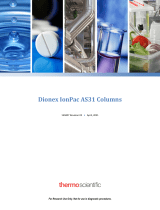
Figure 1 shows the generalized flow schematic for the Ion Chromatography Preconcentration System using a Rheodyne valve.
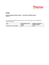
Figure 2 shows the flow scheme using a double stack high pressure Dionex valve.
Figure 1
Ion Chromatography Preconcentration System
Using a Rheodyne Valve
Waste
Sample In
Eluent In
Conductivity
Cell
Concentrator
Column
Guard
Column
Analytical
Column
Waste
Suppressor
(ASRS
®
)
12
3
4
5
6

IonPac AMC-1 Document No. 031262-06 Page 5 of 11
Guard
Column
Analytical
Column
Conductivity
Cell Suppressor
(ASRS)
Concentrator
Column Waste
By-pass
Loop
Eluent
Sample
In
Load
Inject
1
2
3
4
5
6
7
8
Waste
Figure 2
Ion Chromatography Preconcentration System
Using a Double Stack Valve

IonPac AMC-1 Document No. 031262-06 Page 6 of 11
SECTION 3 - OPERATION
Basic plumbing of ion chromatography systems for trace analysis using concentrator columns as well as other useful hints for
minimizing blanks and contamination sources is discussed in Dionex Technical Note 8, “The Use of Concentrator Columns in
Ion Chromatography.”
3.1 SAMPLE LOADING FLOW RATE
Flow rates up to 2 mL/min. have been studied. Recovery of fluoride is better than 96% at 2 mL/min.
3.2 LINEARITY
The correlation coefficients for fluoride, chloride, nitrate and sulfate over the range of 200 to 4000 ng/L are better than 0.9997
for all peaks, using a 2-mm IonPac AS14 analytical column with standard eluent and an ASRS suppressor in recycle mode.
3.3 REAGENT AND SAMPLE HANDLING
At trace analyte concentration levels (µg/L), the results of analysis depend on carefully following good laboratory practices. All
sources of contamination must be eliminated. The following sections focus on critical points that must be observed when using
concentrator columns. Proper consideration of these points will enable the analyst to obtain accurate and reproducible results at
trace analyte levels.
3.3.1 Water Quality
All water used in the preparation of standards and eluents must be deionized water with a specific resistance of 18.2 megohm-
cm. The quality of the dilution water must be determined by Ion Chromatography since even deionized water with a specific
resistance of 18.2 megohm-cm may contain trace levels of the ions of interest. To do this, analyze your water in exactly the same
manner as you would your sample.
3.3.2 Sample Collection and Storage
At trace analyte concentration levels (µg/L), chances of contamination during collection or storage are high. Every container and
every procedural step constitutes a potential source of contamination. Polystyrene containers with leak-tight caps can be used to
store 1 to 5 µg/L levels of inorganic and organic anions for up to 8 days. Recommended storage vessels are Corning tissue culture
flasks. The following procedure should be used for storage of µg/L level samples:
A. Rinse the polystyrene container and cap twice with deionized water having a specific resistance of 18.2 megohm-cm.
Fill the container until it overflows, cap it securely, and soak for 4 hours.
B. Empty the container and refill it with deionized water having a specific resistance of 18.2 megohm-cm. Cap the
container securely. It should remain filled at least 24 hours before sample collection.
C. Empty the container and rinse it twice with the sample to be collected. Fill the container with the sample until it
overflows and then cap the container securely. Be sure that the sample line does not touch the container.
NOTE
Never use plastic syringes with rubber pistons for any loading of trace ions. These materials cause non-reproducible
results.

IonPac AMC-1 Document No. 031262-06 Page 7 of 11
3.3.3 Standards
It is good practice to run standards at the beginning, middle, and end of each day to ensure constant instrument response. Because
external standard quantitation is used, it is critical that standard solutions are correctly prepared.
A. 1,000 mg/L stock standard solutions should be prepared by accurately weighing amounts of salts as described in your
instrument manual. These solutions are stable over a period of several months.
B. 1 mg/L stock standard solutions may be prepared by diluting 1 mL of 1,000 ppm stock standard to 1,000 mL in a
volumetric flask. These solutions should then be transferred to clean polystyrene containers. They may be stored for
one month.
C. 1 mg/L working standard solutions may be prepared by diluting 1 mL of the 1 mg/L stock standard to 1,000 mL. These
working standards are stored in polystyrene containers. They are stable up to 8 days but it is recommended that they
be prepared daily since standard response is critical in the results of your analysis.
3.4 CONCENTRATOR CAPACITY
3.4.1 Capacity Considerations for Concentrators
As in all ion exchange systems, the resin has a finite capacity. It can strip a given amount of ions from water. When the capacity
of the concentrator is exceeded, the stripping will not be quantitative. This condition is referred to as column overload.
When estimating the capacity of a concentrator, one must remember that the column is used in a dynamic state where the liquid
containing the analytes is flowing over the resin at a finite rate. This reduces the capacity somewhat since the analyte ions have
less time to interact with the resin surface.
Low concentrator column capacity creates the following practical implications:
A. Trace analysis of an analyte is difficult in the presence of mg/L concentrations of species which exhibit higher or
similar affinities for the resin (e.g. SO42-, NO3-, S2-, OH-, etc.). If the dynamic column capacity is exceeded, high affinity
ions will displace the analytes on the ion exchange sites and result in their elution to waste during the loading process.
NOTE
At higher concentrations, all ions which are ion-exchanged on the resin may be potential sources of interference. This
includes ions which are not detected by the conductivity detector (e.g., S-, OH-, CN-). The dynamic column capacity
should serve as a guideline in evaluating potential interferences.
B. Conversely, qualitative analysis of ions with higher affinities for the resin in the presence of high concentrations of
ions with low affinities is possible (e.g., analysis of SO42- in the presence of high concentrations of Cl-). Again, the key
to successful analysis is that the ionic content of the high affinity ion to be quantitated may not exceed the effective
column capacity. The order of elution is a good reference to relative affinity.
C. Do not dilute samples to be concentrated in eluent because the eluent ions will elute the analyte ions.
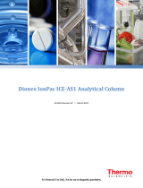
D. A plot of response versus volume concentrated should be generated as in Figure 3, “Response Versus Volume
Concentrated,” for determination of the maximum amount of sample or standards that can be quantitatively loaded.
In Figure 3, the break in the curve where linearity starts to change is 100 mL concentrated. For practical purposes the
amount concentrated for a series of samples should be 75% of this value. This will ensure a safety margin for samples
having slightly higher ionic concentrations.

IonPac AMC-1 Document No. 031262-06 Page 8 of 11
50 100 150 200
600
800
400
200
VOLUME OF 0.014 meq/L SAMPLE CONCENTRATED (mL)
Relative Peak Height
3.4.2 Determination of Concentrator Column Breakthrough Volume
The breakthrough volume of an analyte ion is that volume of sample which causes an ion of interest to be eluted from the
concentrator column rather than retained or concentrated on the concentrator column.
The breakthrough is dependent upon the following:
A. The volume of sample loaded
B. The rate at which the sample is loaded
C. The pH of the sample
D. The ionic strength of the sample
E. The amount and capacity of resin in the column
The breakthrough volume is determined as follows:
A. Prepare 1 L of a solution that closely simulates the type of sample to be analyzed. For example, if the sample contains
high levels of ammonium, the simulated sample should also contain ammonium. Ammonia in solution exists as
ammonium hydroxide ions. The resulting ammonium ion will act as an eluent.
B. Prepare a 1 mg/L standard of the first eluting ion of interest (e.g., Cl-).
C. Set up the Ion Chromatograph, as shown in Figure 4, “Determination of the Breakthrough Volume,” and equilibrate
the concentrator column with eluent at the concentration flow rate needed to achieve a stable baseline.
D. Switch to the simulated sample as an eluent and manually inject a 50 mL portion of the 1 mg/L standard.
E. Record the resulting chromatogram and calculate the breakthrough volume, as shown in Figure 4.
F. For practical purposes, the volume concentrated should below 75% of the breakthrough volume.
Figure 3
Response Versus Volume Concentrated

IonPac AMC-1 Document No. 031262-06 Page 9 of 11
1. Flush concentrator column with eluent.
2. Load 50 µL loop with 1 mg/L standard of first eluting ion of interest.
3. Switch from eluent to simulated sample and inject 50 µL of standard.
4. Determine breakthrough volume as follows:
Figure 4
Determination of the Breakthrough Volume
Breakthrough Volume
60 mL
(15 min x 4 mL/min)
Inject First eluting Ion
of interest
Time (min)
0 2 4 6 8 101214 16182022
Standard
Standard Pump
(Eluent) Simulated
Sample
Eluent Pump
Sampling Valve
50 µL Loop
Waste
AMC-1
Suppressor (ASRS) Waste
Conductivity
Cell

IonPac AMC-1 Document No. 031262-06 Page 10 of 11
SECTION 4 - TROUBLESHOOTING GUIDE
The purpose of the troubleshooting guide is to help you solve operating problems that may arise while using the IonPac Anion
MicroConcentrator (AMC-1) column. For more information on problems that originate with the Ion Chromatograph, refer to the
appropriate operator's manual.
NOTE
Changing the bed supports on the AMC-1 is not recommended.
4.1 HIGH BACKGROUND NOISE OR BASELINE INSTABILITY
Normally, problems such as high background, noise or baseline instability will not be attributable to the lonPac Anion
MicroConcentrator (AMC-1) Column. These problems usually originate in either the analytical column or the post-column
detection chemistry. Before checking the AMC-1 as the source of system background noise, consult the appropriate troubleshooting
sections in the analytical column Installation Instructions and Troubleshooting Guide, the Ion Chromatograph Operator’s Manual
and the detector manual.
If the source of the high background noise is isolated to the AMC-1, then proceed with the following steps:
A. Make sure that the eluents and regenerant are correctly formulated.
B. Make sure that the eluents are made from chemicals with the recommended purity (see Section 3, “Operation”).
C. Make sure that deionized water used to prepare the reagents has a specific resistance of 18.2 megohm-cm.
4.2 POOR PEAK SHAPE
In some instances, poor peak shape may be caused by a contaminated AMC-1. To clean the AMC-1, see Section 5.4, “Column
Cleanup.”

IonPac AMC-1 Document No. 031262-06 Page 11 of 11
SECTION 5 - COLUMN CARE
5.1 RECOMMENDED OPERATING PRESSURES
Operating a column above its recommended pressure limit can cause irreversible loss of column performance. The maximum
recommended operating pressure for the IonPac Anion MicroConcentrator (AMC-1) Column is 3000 psi.
5.2 COLUMN START-UP
The column is shipped with 5 mM Na2CO3/2 mM NaHCO3 as the storage solution.
5.3 COLUMN STORAGE
The IonPac Anion MicroConcentrator (AMC-1) Column should be stored in the Carbonate/Bicarbonate form (such as 5 mM
Na2CO3/2 mM NaHCO3).
5.4 COLUMN CLEANUP OF POLYVALENT ANIONS AND BASE-SOLUBLE CONTAMINANTS
A. Prepare a 100 mL solution of 0.1 Na2CO3.
B. Disconnect the guard, analytical columns and the Anion Self Regenerating Suppressor (ASRS) from the injection
valve and the Conductivity Module. Disconnect the Gradient Mixer or Anion Trap Column (ATC-3) from the Gradient
Pump (GP50 or GP40). Connect the IonPac MicroConcentrator (AMC-1) Column directly to the GP50 or GP40. Direct
the effluent from the AMC-1 directly to a waste container.
C. Set the flow rate to 0.5 mL/min.
D. Pump the 0.1 M Na2CO3 solution through the column for 15 minutes.
E. Equilibrate the AMC-1 with eluent for 15 minutes at 0.5 mL/min before resuming normal operation.
F. Reconnect the guard, analytical column and the Anion Self Regenerating Suppressor (ASRS) between the injection
valve and the conductivity module. Reconnect the Gradient Mixer or Anion Trap Column (ATC-3) between the
Gradient Pump and the Injection Valve. Resume operation.
5.5 COLUMN CLEANUP OF ORGANIC/ANIONIC CONTAMINANTS
A. Prepare a 100 mL solution of 0.1 Na2CO3/60% acetonitrile.
B. Disconnect the guard, analytical columns and the Anion Self Regenerating Suppressor (ASRS) from the injection
valve and the Conductivity Module. Disconnect the Gradient Mixer or Anion Trap Column (ATC-3) from the Gradient
Pump. Connect the IonPac MicroConcentrator (AMC-1) Column directly to the Gradient Pump. Direct the effluent
from the AMC-1 directly to a waste container.
C. Set the flow rate to 0.5 mL/min.
D. Pump the 0.1 M Na2CO3/60% acetonitrile solution through the column for 15 minutes.
E. Equilibrate the AMC-1 with eluent for 15 minutes at 0.5 mL/min before resuming normal operation.
F. Reconnect the guard, analytical column and the Anion Self Regenerating Suppressor (ASRS) between the injection
valve and the conductivity module. Reconnect the Gradient Mixer or Anion Trap Column (ATC-3) between the
Gradient Pump and the Injection Valve. Resume operation.
-
 1
1
-
 2
2
-
 3
3
-
 4
4
-
 5
5
-
 6
6
-
 7
7
-
 8
8
-
 9
9
-
 10
10
-
 11
11


Thermo Fisher Scientific IonPac AMC-1 Anion Microconcentrator Column User manual
- Type
- User manual
Ask a question and I''ll find the answer in the document
Finding information in a document is now easier with AI
Related papers
-
 Thermo Fisher Scientific IonPac AC15 Concentrator Column User manual
-
 Thermo Fisher Scientific Dionex IonPac AS11-HC-4?m Column User manual
-
 Thermo Fisher Scientific IonPac AC10 Concentrator Column User manual
-
 Thermo Fisher Scientific Dionex IonPac AS31 Columns User manual
-
 Thermo Fisher Scientific Dionex IonPac AS16-4µm Columns User manual
-
 Thermo Fisher Scientific Dionex Eluent Generator Cartridges User manual
-
 Thermo Fisher Scientific IonPac Mixer Operating instructions
-
 Thermo Fisher Scientific Dionex IonPac Fast Anion III Columns User manual
-
 Thermo Fisher Scientific Dionex IonPac ICE-AS1 Analytical Column User manual
-
 Thermo Fisher Scientific Dionex IonPac Fast Anion IIIA User manual


Other documents
-
Thermo Scientific IONPAC AS2 ANALYTICAL COLUMN User manual
-
 Dionex ICS-2100 User manual
-
Metrohm 940 Professional IC Vario TWO/SeS/PP Owner's manual
-
Shodex SI-90 4E (IC) Operating instructions
-
-
-
Metrohm 930 Compact IC Flex ChS/Deg Owner's manual
-
-
-
