Page is loading ...

PRODUCT MANUAL
IONPAC® AC10 CONCENTRATOR COLUMN
(4 x 50 mm, P/N 052960)
(2 x 50 mm, P/N 052961)
©DIONEX Corporation, 1997, 1998, 2002
Document No. 034529
Revision 06
31 October 2002
QUICKSTART STEPS AND LINKS
Click blue text below to get started.
1. See Section 2, "Installation" for IonPac AC10 concentrator installation instructions.
2. See Section 3, "Operation" for IonPac AC10 concentrator operation instructions.
3. See "Column Care" for column cleanup and long-term storage recommendations.

IonPac AC10 Manual Document No. 034529-06 Page 2 of 12
TABLE OF CONTENTS
SECTION 1 - INTRODUCTION ...................................................................................................... 3
SECTION 2 - INSTALLATION ....................................................................................................... 5
2.1 Column Description................................................................................................................................................. 5
2.2 System Requirements for the IonPac AC10 Concentrator Column ..................................................................5
SECTION 3 - OPERATION.............................................................................................................. 6
3.1 Sample Loading ....................................................................................................................................................... 6
3.2 Reagent and Sample Handling ............................................................................................................................... 6
3.2.1 Water Quality ............................................................................................................................................................ 6
3.2.2 Sample Collection and Storage.................................................................................................................................. 7
3.2.3 Standards ................................................................................................................................................................... 7
3.3 Concentrator Capacity ........................................................................................................................................... 7
3.3.1 Capacity Considerations for Concentrators ............................................................................................................... 7
3.3.2 Determination of Concentrator Column Breakthrough Volume ............................................................................... 9
SECTION 4 - TROUBLESHOOTING GUIDE ............................................................................ 11
4.1 High Back Pressure from a Contaminated Inlet Bed Support ......................................................................... 11
4.2 High Background, Noise or Baseline Instability ................................................................................................ 12
4.3 Poor Peak Shape .................................................................................................................................................... 12

IonPac AC10 Manual Document No. 034529-06 Page 3 of 12
SECTION 1 - INTRODUCTION
The IonPac® AC10 Concentrator Column is designed primarily for high purity water analysis. The function of the AC10 is to strip
ions from a measured volume of a relatively clean aqueous sample matrix. This process “concentrates” the desired analyte species
onto the AC10 leading to a lowering of detection limits by 2-5 orders of magnitude. The unique advantage of the AC10 to the
analytical chemist is the capability of performing routine trace analyses of sample matrix ions at µg/L levels without extensive
and laborious sample pretreatment.
For trace level analysis, the 20 µL loop on the injection valve of the Ion Chromatograph is replaced with the AC10. A sample
loading pump is required to pump sample through the AC10. The AC10 has been optimized for use with the IonPac AS10
Analytical Column to effectively concentrate anions from deionized water and common power plant waters.
Sample volumes up to 100 mL of ultrapure water can be concentrated to achieve sensitivities up to parts per trillion. Normal
volumes of 10 to 20 mL have been used to detect sub part per billion levels of each of the anions in waters containing up to 1.2%
boric acid, 20 part per million morpholine and one part per million ammonium. This column is also useful in determining tenths
of part per million levels of anions in component cooling water containing high levels of nitrite.
The AC10 is packed with a solvent compatible, microporous ethylvinylbenzene/divinylbenzene copolymer that is agglomerated
with a quaternary amine functionalized latex. The capacity of the AC10 is 4.0 µeq/column with a void volume of approximately
207 µL. The physical rigidity of this resin allows the AC10 to be used at pressures up to 4,000 psi. The AC10 can be readily
converted between the hydroxide and the salt form without significant changes in the operating pressure and is compatible with
samples containing organic solvent. The recommended maximum flow rate is 3 mL/min for the AC10 4-mm.
The AC10 is available in a 2 x 50 mm format for operation with the IonPac AS10 2-mm Analytical Column. This concentrator
has been optimized to minimize the dead volume contributed by the concentrator during 2-mm operation. The recommended
maximum flow rate is 1.25 mL/min for the AC10 2-mm. For more information on the installation and operation of 2-mm columns,
see the Product Manual for the IonPac AS10 and AG10 (Document No. 034519).
The IonPac AS10, AG10 and AC10 Columns have 10-32 PEEK end fittings for use with ferrule/bolt liquid line fittings. If you
have an Ion Chromatograph with Tefzel® liquid lines having 1/4-28 ThermoFlare™ fittings, it will be necessary to obtain one or
more Tefzel liquid lines with a PEEK bolt and ferrule fitting on one end and a 1/4-28 ThermoFlare fitting on the other end. See
“Installation of DIONEX Liquid Line Fittings,” for detailed instructions on purchasing or making these lines.
Table 1
IonPac AC10 Trap Column Packing Specifications
Column Particle SubstrateaLatex LatexbColumn Functional Group Hydrophobicity
Diameter X-linking Diameter X-Linking Capacity
µm % nm % µeq/column
AC10 13 55 160 5 0.8 Alkanol quaternary Low
2 x 50 mm ammonium
AC10 13 55 160 5 4.0 Alkanol quaternary Low
4 x 50 mm ammonium
Table 2
AC10 Trap Column Operating Parameters
Standard Maximum
Column Typical Back Pressure Flow Rate Flow Rate
psi (MPa) mL/min mL/min
AC10 4-mm Concentrator Column < 300 (2.07) 1.0 3.0
AC10 2-mm Concentrator Column < 300 (2.07) 0.25 1.25

IonPac AC10 Manual Document No. 034529-06 Page 4 of 12
Always remember that assistance is available for any problem that may be encountered during the shipment or
operation of DIONEX instrumentation and columns through the DIONEX North America Technical Call Center
at 1-800-DIONEX-0 (1-800-346-6390) or through any of the DIONEX Offices listed in, “DIONEX Worldwide
Offices.”

IonPac AC10 Manual Document No. 034529-06 Page 5 of 12
SECTION 2 - INSTALLATION
For information on the general installation of concentrator columns in a variety of systems, see DIONEX Technical Note #8, “The
Use of Concentrator Columns in Ion Chromatography.”
2.1 Column Description
The IonPac AC10 Concentrator Column consists of the following components:
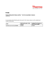
2.2 System Requirements for the IonPac AC10 Concentrator Column
Figure 2, “Configuration for Determining Trace Levels of Anions,” shows the generalized flow schematic for trace level anion
chromatography.
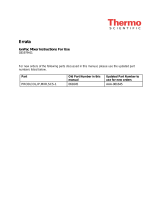
Figure 1
AC10 Column Components
1. Bed Support Assembly
2. 10-32 Ferrule Column End Fitting
3. 10-32 Ferrule Plug
(See Section 4.1, “High Back Pressure from a Contaminated Bed Support”
for hardware part numbers)
TOP END
13
2
F L O W
IonPac
AC10
P/N xxxxxx S/N xxxx
Figure 2
Configuration for Determining Trace Levels of Anions
1
6
5
4
2
3
Waste
Conductivity
Cell
Analytical
Column
Guard
Column
AC10
Sample from the
Sampl e Pump
Eluent In
Gas
Separator
Waste
Tube
Waste
0
1
Load
Inj
Ani on Sel f- Reg ener ati ng
Suppressor (ASRS)
10-32
1/ 4- 2 8
REG EN O UT
ELUENT I N
10-32
1/4- 28
EL UE NT O UT
REG EN I N
Anion Se l f-Regenerating
P/ N xxx xxx S/ N xxx x
Sup pr e s s o

IonPac AC10 Manual Document No. 034529-06 Page 6 of 12
SECTION 3 - OPERATION
3.1 Sample Loading
Sample loading is performed with a separate positive displacement pump such as the DIONEX DQP pump (P/N 035250), DXP
Pump (P/N 043047) or the Reagent Pump (P/N 042043). Pump flow rates of approximately 3 mL/min can be used while
maintaining sample concentration efficiencies high enough to ensure good quantification. To prevent overloading of the AC10
and/or the loss of sample analytes, concentration linearity over the desired analytical concentration range should be determined
(see Section 3.4.1, “Capacity Considerations for Concentrators”).
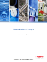
The flow direction during the concentration step is critical. After the sample has been loaded onto the AC10 in the direction
opposite to the eluent flow, it is then “backflushed” with eluent onto the guard and analytical columns (see Figure 3, “Loading
the IonPac AC10 Concentrator Column”). This configuration concentrates the anions in a compact band at the bottom of the
AC10. When injected, all of the ions are rapidly eluted off the AC10 and onto the guard and analytical columns. If the sample
is loaded onto the AC10 in the same flow direction as the eluent flow, the anions are concentrated at the head of the column rather
than at the bottom. When injected, the anions begin chromatographic separation on the concentrator before reaching the guard
and analytical columns. Normally the function of the concentrator is to strip the ions of interest from the sample matrix and not
to act as an analytical column. In order to ensure maximum system performance, it is recommended that concentration always
be performed in a “backflush” manner.
3.2 Reagent and Sample Handling
The use of the IonPac AC10 Concentrator Column has certain limitations. At trace analyte concentration levels (µg/L), the results
of the analysis depend on carefully following good laboratory practices. All sources of contamination must be eliminated. The
following sections focus on critical points that must be observed when using concentrator columns. Proper consideration of these
points will enable the analyst to obtain accurate and reproducible results at trace analyte levels.
3.2.1 Water Quality
All water used in the preparation of standards and eluents should be Type I Reagent Grade Water with a specific resistance of
18.2 megohm-cm. The quality of the dilution water must be determined by Ion Chromatography since even deionized water with
a specific resistance of 18.2 megohm-cm may contain trace levels of the ions of interest. To do this, analyze your water in exactly
the same manner as you would your sample.
Figure 3
Loading the IonPac AC10 Concentrator Column
1
6
5
4
2
3
Sample from the
sampl e pump
AC10
Waste
Load
1
6
5
4
2
3
AC10
Inject
Eluent IN
To guard and
analytical columns

IonPac AC10 Manual Document No. 034529-06 Page 7 of 12
3.2.2 Sample Collection and Storage
At trace analyte concentration levels (where, 1 µg/L = 1 ppb), chances of contamination during collection or storage are high.
Every container and every procedural step constitutes a potential source of contamination. Polystyrene containers with leak-tight
caps can be used to store 1 to 5 µg/L levels of inorganic and organic anions for up to 8 days. Recommended storage vessels are
Corning tissue culture flasks (Should not have cap seal). The following procedure should be used for storage of µg/L level samples:
A. Rinse the polystyrene container and cap twice with deionized water having a specific resistance of 18.2 megohm-cm.
Fill the container until it overflows, cap it securely, and soak for 4 hours. Use gloves for critical work.
B. Empty the container and refill it with deionized water having a specific resistance of 18.2 megohm-cm. Cap the
container securely. It should remain filled at least 24 hours before sample collection.
C. Empty the container and rinse it twice with the sample to be collected. Fill the container with the sample until it
overflows and then cap the container securely.
NOTE
Never use plastic syringes with rubber pistons for any loading of trace ions. These materials cause non-
reproducible results.
3.2.3 Standards
It is good practice to run standards at the beginning, middle, and end of each day to ensure constant instrument response. Because
external standard quantification is used, it is critical that standard solutions are correctly prepared.
A. 1,000 mg/L stock standard solutions should be prepared by accurately weighing amounts of salts as described in your
instrument manual. These solutions are stable over a period of several months when refrigerated.
B. 1 mg/L stock standard solutions may be prepared by diluting 1 mL of 1,000 mg/L stock standard to 1,000 mL in a
volumetric flask. These solutions should then be transferred to clean polystyrene containers. They may be stored for
one month if refrigerated.
C. 1 µg/L working standard solutions may be prepared by diluting 1 mL of the 1 mg/L stock standard to 1,000 mL. These
working standards are stored in polystyrene containers. They are stable up to 8 days but it is recommended that they
be prepared daily since standard response is critical in the results of your analysis.
3.3 Concentrator Capacity
3.3.1 Capacity Considerations for Concentrators
As in all ion exchange systems, the resin has a finite capacity. It can strip a given amount of ions from water. When the capacity
of the concentrator is exceeded, the stripping will not be quantitative. This condition is referred to as column overload.
When estimating the capacity of a concentrator, one must remember that the column is used in a dynamic state where the liquid
containing the analytes is flowing over the resin at a finite rate. This reduces the capacity since the analyte ions have less time
to interact with the resin surface.

IonPac AC10 Manual Document No. 034529-06 Page 8 of 12
Low concentrator column capacity creates the following practical implications:
A. Trace analysis of an analyte is difficult in the presence of mg/L concentrations of species which exhibit higher or
similar affinities for the resin (e.g. SO4
2-, NO3
-, S2-, OH, etc.). If the dynamic column capacity is exceeded, high affinity
ions will displace the analytes on the ion exchange sites and result in their elution to waste during the loading process.
NOTE
At higher concentrations, all ions which are ion-exchanged on the resin may be potential sources of
interference. This includes ions which are not detected by the conductivity detector (e.g., S2-, OH-, CN-). The
dynamic column capacity should serve as a guideline in evaluating potential interferences.
B. Conversely, qualitative analysis of ions with higher affinities for the resin in the presence of high concentrations of
ions with low affinities is possible (e.g., analysis of SO4
2- in the presence of high concentrations of F-
or acetate). Again,
the key to successful analysis is that the total ionic content of the sample may not exceed the effective column capacity.
C. Do not dilute samples to be concentrated in eluent because the eluent ions elute the ions of interest.
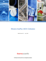
D. A plot of response versus volume concentrated should be generated similar to Figure 4, “Response versus Volume
Concentrated,” for determination of the maximum amount of sample or standards that can be quantitatively loaded.
The curve loses linearity above 100 mL volume concentrated. Therefore volume greater than 100 mL should not be
used for quantification. For practical purposes the volume concentrated for this series of samples should be 75% of
this value. This will ensure that there is a safety margin for samples in the series having slightly higher ionic
concentrations. See Figure 4, “Response versus Volume Concentrated.”
VOLUME CONCENTRATED (mL of 25 mg/L Fluoride)
(Each point is the average of three runs.)
µS
Figure 4
Response versus Volume Concentrated
30
20
10
0
120100806040200

IonPac AC10 Manual Document No. 034529-06 Page 9 of 12
3.3.2 Determination of Concentrator Column Breakthrough Volume
The breakthrough volume of an analyte ion is that volume of sample which causes an ion of interest to be eluted from, rather than
remain retained or concentrated on, the concentrator column.
The breakthrough is dependent upon the following:
A. The volume of sample loaded
B. The rate at which the sample is loaded
C. The pH of the sample
D. The ionic strength of the sample
E. The amount and capacity of resin in the column
The breakthrough volume is determined as follows:
A. Prepare 1 L of a solution that closely simulates the type of sample to be analyzed. For example, if the sample
contains high levels of ammonia, the simulated sample should also contain ammonia. Ammonia in typical solutions
usually exists as ammonium hydroxide ions. The resulting hydroxide ion will act as an eluent.
B. Prepare a 1 mg/L standard of the first eluting ion of interest (e.g., F-).
C. Set up the Ion Chromatograph, as shown in Figure 5, “Instrument Setup for the Determination of the Breakthrough
Volume,” and equilibrate the concentrator column with eluent at the concentration flow rate needed to achieve a stable
baseline.
D. Switch to the simulated sample as an eluent and manually inject a 50 µL portion of the 1 mg/L standard.
E. Record the resulting chromatogram and calculate the breakthrough volume, as shown in the example in Figure
6, “Example Determination of the Breakthrough Volume.”
F. For practical purposes, the volume concentrated should be below 75% of the breakthrough volume.
NOTE
Additional information on breakthrough can be found in DIONEX Technical Note #8, “The Use of Concentrator
Columns in Ion Chromatography.”

IonPac AC10 Manual Document No. 034529-06 Page 10 of 12
Figure 5
Instrument Setup for the Determination of the Breakthrough Volume
Figure 6
Example Determination of the Breakthrough Volume
1
6
5
4
2
3
Waste
Conductivity
Cell
AC10
Syringe Loaded
Si ng le Ion Sampl e
Eluent In
Gas
Separator
Waste
Tube
Waste
0
1
Load
Inj
Anion Self-Regenerating
Suppressor (ASRS)
Where: E1 = The Eluent f or t he Analysis
E2 = The Simulated Sample
50 µL Injecti on Loop
10- 32
1/ 4- 2 8
REG EN O UT
EL UENT I N
10-32
1/ 4- 28
EL UE NT O UT
REG EN I N
Anion Se lf-Regenerating
P/ N xxxxx x S/ N xxxx
Sup pr es s
024
6810
12 14 16 18 20 22
Time(min)
thatthe sim ulated sam ple is pum ped through the
A C 10 after the single ion injection
Inject
B reakthrough V olum e
#mLSimulated S am ple= Time(min)xFlow R ate(mL/min)

IonPac AC10 Manual Document No. 034529-06 Page 11 of 12
SECTION 4 - TROUBLESHOOTING GUIDE
The purpose of the Troubleshooting Guide is to help you solve operating problems that may arise while using the IonPac AC10
Concentrator Column. For more information on problems that originate with the Ion Chromatograph, refer to the Troubleshooting
Guide in the appropriate operator’s manual. If you cannot solve the problem on your own, call the nearest DIONEX Office (see,
“DIONEX Worldwide Offices”).
4.1 High Back Pressure from a Contaminated Inlet Bed Support
If the AC10 displays high back pressure, the bed support in the column inlet may be contaminated. Follow the instructions below
to change the bed support assembly using one of the two spare bed support assemblies included in the ship kit provided with the
column.
A. Disconnect the column from the system.
B. Carefully unscrew the inlet (top) column end fitting, using two open-end wrenches.
C. Remove the bed support. Turn the end fitting over and tap it against a benchtop or other hard, flat surface to remove
the bed support and seal assembly. If the bed support must be pried out of the end fitting, use a sharp pointed object
such as a pair of tweezers, but be careful that you DO NOT SCRATCH THE WALLS OF THE END FITTING.
Discard the old assembly.
D. Place a new bed support assembly in the end fitting. Use the end of the column to carefully start the bed support
assembly into the end fitting.
IonPac AS10/AG10/AC10
4-mm 2-mm
Columns Columns
(P/N) (P/N)
Analytical Column (AS10) 043118 043123
Guard Column (AG10) 043119 043124
Concentrator Column (AC10) 043133 043134
Bed Support Assembly 043275 044689
End Fitting 052809 043278
E. Screw the end fitting back onto the column. Tighten it fingertight and then using two open-end wrenches, tighten
it an additional 1/4 turn (25 in x lb). Tighten further only if leaks are observed.
NOTE
If any of the column packing becomes lodged between the end of the column and the bed support washer assembly,
no amount of tightening will seal the column. Make sure that the washer and the end of the column are clean before
screwing the end fitting back onto the column.
F. Reconnect the column to the system and resume operation.

IonPac AC10 Manual Document No. 034529-06 Page 12 of 12
4.2 High Background, Noise or Baseline Instability
Normally, problems such as high background, noise or baseline instability will not be attributable to the IonPac AC10
Concentrator Column. These problems usually originate in either the analytical column or the post-column detection chemistry.
Before checking the AC10 as the source of system background noise, consult the appropriate troubleshooting sections in the
analytical column Product Manual, the Ion Chromatograph Operator’s Manual and the detector manual.
If the source of the high background noise is isolated to the AC10, then proceed with the following steps:
A. Make sure that the eluents and regenerant are correctly formulated.
B. Make sure that the eluents are made from chemicals with the recommended purity (see Section 3, “Operation”).
C. Make sure that deionized water used to prepare the reagents has a specific resistance of 18.2 megohm-cm.
D. If you cannot solve the problem on your own, call the nearest DIONEX Office (see, “DIONEX Worldwide Offices”).
4.3 Poor Peak Shape
In some instances, poor peak shape may be caused by a contaminated AC10. To clean the AC10, see Column Care, “Column
Cleanup of Polyvalent Anions and Base-Soluble Contaminants” and Column Care, “Column Cleanup of Organic/Anionic
Contaminants.” If you cannot solve the problem on your own, call the nearest DIONEX Office (see, “DIONEX Worldwide
Offices”).

IonPac AC10 Column Care Document No. 034529C06 Page 1 of 1
RECOMMENDED OPERATING PRESSURES
Operating a column above its recommended pressure limit can cause irreversible loss of column performance. The
maximum recommended operating pressure for the IonPac AC10 Concentrator Column is 4,000 psi.
COLUMN START-UP
The column is shipped with 0.1 mM NaOH as the storage solution.
COLUMN STORAGE
The IonPac AC10 column should be stored in the hydroxide form.
COLUMN CLEANUP OF POLYVALENT ANIONS AND BASE-SOLUBLE CONTAMINANTS
A. Prepare a 500 mL solution of 0.5 M NaOH.
B. Disconnect the guard, analytical column, and the suppressor from the injection valve and the conductivity module.
Disconnect the gradient mixer or anion trap column, if used, from the gradient pump. Connect the AC10 directly to
the GPM. Direct the effluent from the AC10 directly to a waste container.
C. Set the flow rate to 1.0 mL/min for the cleanup of the AC10 4-mm column.
D. Set the flow rate to 0.25 mL/min for the cleanup of the AC10 2-mm column.
E. Pump the 0.5 M NaOH solution through the column for 15-30 minutes.
F. Equilibrate the AC10 with eluent for 15 minutes before resuming normal operation.
G. Reconnect the guard, analytical column, and the suppressor between the injection valve and the conductivity
module. Disconnect the gradient mixer or anion trap column, if used, between the gradient pump and the injection
valve. Resume operation.
COLUMN CLEANUP OF POLYVALENT ANIONS AND BASE-SOLUBLE CONTAMINANTS
A. Prepare a 500 mL solution of 200 mM HCl/50% ACN.
B. Disconnect the guard, analytical column, and the suppressor from the injection valve and the conductivity module.
Disconnect the gradient mixer or anion trap column, if used, from the gradient pump. Connect the AC10 directly to
the GPM. Direct the effluent from the AC10 directly to a waste container.
C. Set the flow rate to 1.0 mL/min for the cleanup of the AC10 4-mm column.
D. Set the flow rate to 0.25 mL/min for the cleanup of the AC10 2-mm column.
E. Pump deionized water having a specific resistance of 17.8 megohm-cm or greater through the column for 15-30
minutes.
F. Pump the 0.5 M NaOH solution through the column for 15-30 minutes.
G. Equilibrate the AC10 with eluent for 15 minutes before resuming normal operation.
H. Reconnect the guard, analytical column, and the suppressor between the injection valve and the conductivity
module. Disconnect the gradient mixer or anion trap column, if used, between the gradient pump and the injection
valve. Resume operation.
/