Page is loading ...

Publication: AMEN00041 2017-11-06
This manual covers units ordered 11-6-2017
to date for Encoder, i-Comm, GUI change.
For doors ordered prior to 11-6-2017 refer to
AMEN00041-2017-02-01.
Installation/Owner’s Manual
Language: English (Hazards are in English and French)
The English version of this manual shall prevail over any
error in, or conflicting interpretation of, any translations.
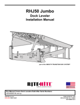
TRAKLINE™
ROLL DOOR - MODEL 8910
FOLD DOOR - MODEL 8920

SAFETY WARNINGS . . . . . . . . . . . . . . . . . . . . . . . . . . . . . . . .3
PRELIMINARY INSTALLATION CHECKS . . . . . . . . . . . . . . . .4
DOOR JAMB PREPARATION . . . . . . . . . . . . . . . . . . . . . . . . .5
SIDEFRAME INSTALLATION . . . . . . . . . . . . . . . . . . . . . . . . .6
ROLLER TUBE INSTALLATION . . . . . . . . . . . . . . . . . . . . . . .7
REAR HEADER BRACE INSTALLATION . . . . . . . . . . . . . . . .8
DRIVE SYSTEM INSTALLATION . . . . . . . . . . . . . . . . . . . . .10
FRONT HEADER BRACE INSTALLATION . . . . . . . . . . . . . .12
V-FLEX STRAP INSTALLATION . . . . . . . . . . . . . . . . . . . . . .14
LIFTING STRAP INSTALLATION . . . . . . . . . . . . . . . . . . . . .15
HEADER COVER / SEAL INSTALLATION . . . . . . . . . . . . . .16
COUNTER BALANCE / THRU-WALL BRAKE RELEASE . . .17
ELECTRICAL INSTALLATION . . . . . . . . . . . . . . . . . . . . . . . .18
I-COMM INPUT / OUTPUT TABLE . . . . . . . . . . . . . . . . . . . .21
PHOTOEYE INSTALLATION . . . . . . . . . . . . . . . . . . . . . . . . .22
COVER / SHROUD INSTALLATION . . . . . . . . . . . . . . . . . . .25
START-UP PROCEDURES . . . . . . . . . . . . . . . . . . . . . . . . . .26
MAINTENANCE PROCEDURES / FINAL CHECKLIST . . . .27
TROUBLESHOOTING . . . . . . . . . . . . . . . . . . . . . . . . . . . . . .28
ELECTRICAL DRAWINGS . . . . . . . . . . . . . . . . . . . . . . . . . .30
EXPLODED VIEWS & PARTS LIST . . . . . . . . . . . . . . . . . . .36
ARCHITECTURAL DRAWING . . . . . . . . . . . . . . . . . . . . . . . .46
WARRANTY . . . . . . . . . . . . . . . . . . . . . . . . . . . . . . .back page
SPECIAL FEATURES
i-COMM™ Universal Controller•
Frequency Drive (VFD) Controlling Speed•
Fast smooth opening with a maximum speed of up to•
40 in/sec.
Motor options of 3 Phase 60 Hertz: 208V, 230V,•
460V, 575V
Motor option with 3Ø 50 Hertz 400V may have•
slower speeds
Interior Rolling Door•
Exterior / Interior Folding Door.•
V-Flex™ Curtain Release System.•
One or Two directional curtain breakaway.•
High Wind package.•
Heavy-duty industrial materials for high cycles and•
minimal wear.
NOTICE TO END USER
Our mission is to “Improve Industrial Safety, Security and
Productivity Worldwide Through Quality and Innovation.”
Thank you for purchasing the TRAKLINE™ ROLL or FOLD
door from RITE-HITE DOORS, INC. The TRAKLINE door is
designed to be a fast, smooth opening, low maintenance door
that provides superior environmental separation while reducing
passage time and temperature loss
The information contained in this manual will allow you to
operate and maintain the door in a manner which will insure
maximum life and trouble free operation.
This manual should be thoroughly read and understood before
beginning the installation, operation or servicing of this door.
Complete Final Checklist prior to leaving site
When ordering parts through Aftermarket or Warranty
department, always include your door serial or RHC# to be
sure that you receive the correct parts. The RHC and serial #
for your door is located on a label on the side of the control
box, Figure 20. The actual parts used on your door may be
different than shown in this manual due to special engineering
or product improvement.
Your local RITE-HITE DOORS, INC. Representative provides a
Planned Maintenance Program (P.M.P.) which can be fitted to
your specific operation. Call your local representative or RITE-
HITE DOORS, INC. at 1-414-355-2600 or toll free at 1-800-
456-0600. If any procedures for the installation, operation or
maintenance of the TRAKLINE have been left out of this
manual or are not complete, contact RITE-HITE DOORS, INC.
Technical Support at 1-563-589-2722.
2Publication: AMEN00041 2017-11-06
PRODUCT INTRODUCTION
TRAKLINE™ MODEL 8910 ROLL / 8920 FOLD Installation/Owner’s Manual Rite-Hite®
Fork lift and scissors lift
Hydro level
10’ [3050] Step ladder
Cordless drill
25’ [7600] Tape measure
Wire strippers and side cutters
6’ [1800] Carpenters level
Utility knife
(2) 15/16in [24] open end wrenches
Hammer
Phillips Screwdriver
Hammer Drill and Cordless Drill (3/8in [10] or 1/2in [13])
#2 Square Driver, and Phillips Bit For Drill
Plumb Bob and Chalkline
18in [460] Clamps (2)
Straps For Lifting Header / Roller Tube (optional)
1/2in [13] & 5/8in [16] masonry and/or drill bit for thru bolting
1/2in [13] , 9/16in [14] open end and/or socket wrench
11/16in x 12in [17 x 300] drill bit for thru bolting
Straight screwdriver (small 1/8in [3] spade)
Tube of Anti-Seize or Grease Lubricant
Set of Allen Wrenches (1/8in, 5/32in)
Caulk Gun and Tubes
1 1/4in [32] & 1 1/2in [38] Open End Wrench
Hole Saw
5/16in [8] Driver Bit For Drill
3/16in [5] Punch
Laser Level
Multi-Meter
Anchors, wall fasteners and shims are not supplied. Solid plastic or
metal shims must fully support the sideframe base plate. Drill or cut
through the shims to allow for the proper installation of the anchor
bolts.
INSTALLATION TOOLS REQUIRED
Gearmotor Rubber Bumpers 15250057 (2)
Fuse 1/2 Amp 600V 51000001 (2)
Fuse 1 Amp 250V 51000002 (1)
Fuse 2 Amp 250V 51000005 (1)
Fuse 1 Amp 600V 51000023 (2)
Kit, 8910/20, Encoder, Bevel 53701005 (1)
Kit, 8910/20, Encoder, Worm 53701039 (1)
Kit, i-COMM 3, Replacement 53701043 (1)
GUI 55150353 (1)
Photoeye Retro-reflective 63900002 (1)
Photoeye T.B. Receiver 63900005 (1)
Photoeye T.B. Emitter 63900036 (1)
RECOMMENDED SERVICE PARTS

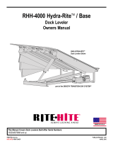
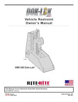
LOCKOUT/TAGOUT PROCEDURES
The Occupational Safety and Health Administration
requires that, in addition to posting safety warnings and
barricading the work area, the power supply has been
locked in the OFF position or disconnected. It is
mandatory that an approved lockout device is utilized. An
example of a lockout device is illustrated. The proper
lockout procedure requires that the person responsible
for the repairs is the only person who has the ability to
remove the lockout device.
In addition to the lockout device, it is also a requirement
to tag the power control in a manner that will clearly note
that repairs are under way and state who is responsible
for the lockout condition. Tagout devices have to be
constructed and printed so that exposure to weather
conditions or wet and damp locations will not cause the
tag to deteriorate or become unreadable.
RITE-HITE Corporation does not recommend any
particular lockout device, but recommends the utilization
of an OSHA approved device
(refer to OSHA regulation
1910.147). RITE-HITE
Corporation also recommends
the review and implementation
of an entire safety program for
the Control of Hazardous
Energy (Lockout/Tagout).
These regulations are
available through OSHA
publication 3120.
Publication: AMEN00041 2017-11-06 3
SAFETY WARNINGS
Rite-Hite® TRAKLINE™ MODEL 8910 ROLL / 8920 FOLD Installation/Owner’s Manual
SAFETY IDENTIFICATION
NOTE:
A Note is used to inform you of important
installation, operation or maintenance information.
Danger indicates the presence of a hazard that
will cause severe personal injury, death.
DANGER
!
Warning indicates the presence of a hazard that
can cause severe personal injury, death.
WARNING
!
Caution indicates the presence of a hazard that
will or can cause minor personal injury, death.
CAUTION
!
Notice communicates installation, operation, or
maintenance information that is safety related
but not hazard related and may cause equipment
or property damage.
NOTICE
GENERAL SAFETY NOTICES
When working with electrical or electronic controls, make
sure that the power source has been locked out and
tagged according to OSHA regulations and approved local
electrical codes.
DANGER
!
Damage or debris may fall into electrical components
causing failure or severe equipment damage, when drilling
holes in the box.
DO NOT turn control box upside down or go too deeply
into the box.
NOTICE
Make sure to barricade the door opening on both sides to
prevent unauthorized use until the door has been
completely installed.
WARNING
!
In freezer and cooler applications where a conduit passes
from a warm to cold temperature zone, the conduit must be
plugged with epoxy. This will help prevent condensation
from forming in the conduit. For more information, see
Section 300-7a of the National Electric Code.
NOTICE
Do not drill holes on top of control box to run conduit, as
dust particles and moisture may cause damage to electrical
components. The safest location is at the bottom. Failure to
do so will void warranty.
NOTICE
A qualified electrician should install the wiring in
accordance with local and national electrical codes.
Use lockout and tagout procedures to avoid injury.
DANGER
!
To reduce risk of injury or death, an earth ground
connection MUST BE made to the green/yellow control
box ground terminal. If metal conduit is used as the
ground connector, an N.E.C. approved ground bushing
and green/yellow wire MUST BE properly attached to the
conduit for connection to the ground terminal.
DANGER
!

PRELIMINARY INSTALLATION CHECKS
4Publication: AMEN00041 2017-11-06
NOTE:
Check for electrical prints included in the parts or
control box. They supersede any prints in this
manual.
Refer to GUI / i-COMM 3 Touch Screen Control
manual for installation.
Refer to Optional LED Countdown drawings for
installation.
Refer to Optional LED Preannounce drawings for
installation.
1. Alternate measurements in brackets are in [metric].
2. Match control box serial number with track serial
number.
3. Make sure you are working at the correct location
and have any required work permits.
4. Inspect installation site to make sure area is free of
overhead obstructions (sprinkler pipes, HVAC
systems, electrical supply lines, etc.) that might
interfere with the lifting of the header assembly
during installation.
5. Detour material handling equipment (fork lift trucks,
etc.) during the installation of the door.
6. Make sure that the electrician is ready to bring the
correct electrical power supply to the door control
box.
7. Make sure that the electrical power can be shut off
without interfering with other plant operations.
8. Move the entire crate of the door components as
close to the door opening as possible.
9. If multiple doors are being installed, it is imperative
to install the proper control box with the matching
door unit. The serial # for your door is on a label
located on the side of the control box and lower
track, page 20.
10. It is not recommended to weld sideframes in place
until door has been tested to ensure proper
operation
11. To verify proper installation, use "Final Checklist" on
page 27.
12. Install Activation & Optional equipment after
verifying door operation.
TRAKLINE™ MODEL 8910 ROLL / 8920 FOLD Installation/Owner’s Manual Rite-Hite®
QTY DESCRIPTION
Crate Containing the following
1 Header Front Brace (w/Curtain and/or V-Flex Straps) (Fold)
1 Header Rear Brace (w/Curtain and/or V-Flex Straps) (Fold)
1 Roller Tube w/Lift Straps (Fold) or Curtain (Roll)
1 Header Front Brace (Roll)
1 Header Rear Brace (Roll)
1 RH Sideframe
1 LH Sideframe
1 Control Box w/Electrical Prints
1 Drive Assembly w/ Motor/Brake Cable
1 Control Box Cable
1 Photoeye Cables for Thru-Beam (optional)
1 Drive Shroud
a/r Header Covers & Extrusions
a/r Sideframe Covers & Extrusions
Parts Box Containing the Following
1 Owner’s Manual
1 Encoder Assembly with hardware
1 Encoder Sprocket Driven
1 Encoder Sprocket Drive
1 Encoder Chain
1 Key, 3/16in x 1/4in x 4 1/2in [5 x 6 x 114 mm] (C.W.)
1 Key, 3/16in x 1/4in x 3 3/4in [5 x 6 x 95 mm](N.C.W.)
2 Bearing Lock Collar
12/14 3/8-16 x 1in [10 x 25] Bolts for Header Braces
12/14 3/8in [M10] Nuts for Header Braces
12/14 3/8in [M10] Lock Washers for Header Braces
12/14 3/8in [M10] Flat Washers for Header Braces
1 #8 x 1/2in [13 mm] Self Tap/Drill Screw
1 #10 Int/Ext Lock Washer
2 Stand Clear Warning Labels
3 #12-14 x 3/4in [19 mm] Self Tap/Drill Screws
1 Gearbox Spacer
1 Gearbox Shaft Lock Collar
TO PREVENT DAMAGE TO CONTENTS, STORE DRY
BETWEEN 40° and 80° F, [4° and 27° C].
NOTICE

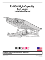
DOOR JAMB
1. Measure door opening width at the top (A) and floor
(B).
2. Measure door opening height at left side (C) and
right side (D).
3. Dimensions from steps 1-2 should be ± 1/2in
[13mm] of the dimensions listed on the serial
number label. If the measurements do not agree,
STOP! Contact your Rite‑Hite representative.
4. Surface MUST be flat, smooth and collinear with
opposite side (E).
5. Using a 6ft [2m] carpenter's level (F), verify that the
door jambs and header are plumb and
perpendicular.
6. Using a laser level (G), place a mark where the
laser is sighted on each side of the jamb to
determine if the floor is level. Measure both sides
from floor to the mark. If floor is not level to ± 1/8in
[3mm], shim under the lower track that (H) that is
the larger measurement.
7. For space clearance requirements, refer to
Architectural Drawings, Pages 46 & 47. or call your
Rite‑Hite Representative.
8. When preparing the sideframe locations, make all
measurements from the centerline of the door
opening.
Measure between the jamb at the top of the opening
and at the floor and divide this measurement in half
and mark the centerline on the wall and on the floor.
Drop a plumb bob from the mark at the top of the
jamb and place a mark on the floor. The dimension
should be within 1/8in [3mm], if not place a mark
half way between these two marks.
(A) - ONE-WAY BREAKAWAY
From centerline, measure 1/2 O.D.W. plus 10 3/8in [263
mm] (D) and place a mark on the floor on each side. This
will offset the location of the V-Flex™ straps, Figure 2.
Overall dimension (H) must be equal to O.D.W. plus 20
3/4in [527 mm] (+1/4in/-0 [6 mm]) and perpendicular to
wall (G).
(B) - ONE-WAY HIGH WIND BREAKAWAY
(8920 only)
From centerline, measure 1/2 O.D.W. plus 12 3/8in [314
mm] (E) and place a mark on the floor on each side. This
will offset the location of the V-Flex™ straps, Figure 2.
Must be equal to O.D.W. plus 24 3/4” [619 mm] for one
way high wind +1/4in/-0 [6 mm] and perpendicular to wall.
(C) - TWO-WAY BREAKAWAY
From centerline, measure 1/2 O.D.W. plus 5in [127 mm]
(F) and place a mark on the floor on each side, Figure 2.
Overall dimension (H) must be equal to O.D.W. plus 10in
[254] +1/4in/-0 [6 mm] and perpendicular to wall.
Publication: AMEN00041 2017-11-06 5
Rite-Hite® TRAKLINE™ MODEL 8910 ROLL / 8920 FOLD Installation/Owner’s Manual
DOOR JAMB PREPARATION
A
B
D
C
E
F
G
H
Figure 1
FD E
G
G
C
A B Figure 2
H

NOTE:
The preferred method of installing the door is to
assemble the door on the floor and raise the door as
a unit. If overhead or side space is limited or the
correct tools are not in place, install the door directly
onto the wall.
Determine the drive side by locating the gearbox
mounting plate at the top. Place the sideframes (A) on
blocks (B) in front of the opening, with the top of the
sideframe toward the opening and the back of the
sideframe facing the floor, Figure 3. An additional block
may need to be placed under the guards (C) at the
bottom of the sideframe to prevent sideframes from
tipping over.
NOTE:
When overhead forklift mast clearance is a issue,
additional support blocks may need to be added
under the roller tube assembly. Securely attach
wooden supports to the roller tube assembly and lift
into position. Use caution not to bend or twist the
header braces, Figure 12.
1. If overhead clearance is available, secure the roller
tube to the fork lift forks and lift.
2. Forklift should be slightly off center toward the drive
side when lifting, as the drive side will be heavier.
Make sure to place clamps on the forks to prevent
the straps from sliding off the forks.
3. Make sure sideframes slide easily on the floor when
lifting. It is helpful if the sideframes can be walked
up with one person on each side, Figure 12.
4. When the door is in place, make sure to square and
level the door and that the sideframes are parallel, if
not raise or lower using shims as necessary. If
shims are required, shims must fully support
sideframe base plate. Drill or cut holes through
shims to allow for anchors.
5. The sideframe should be square to the header
braces, if the sideframes twists when fastening to
the wall shimming may be required.
6. Mark the holes to be drilled, remove the door
assembly from the wall and drill holes through the
wall. RITE-HITE DOORS, INC. recommends that
the sideframe thru bolts use a backing plate for
each bolt.
7. Replace door assembly against the wall, plumb,
level and double-check the overall width
measurements at the bottom of the sideframes.
There should not be more than +1/4in or -0 [6].
See Dimensions A and B on Figure 1. Anchor the
door to the wall and floor using the holes provided in
the back of the sideframe and the bottom plate.
6Publication: AMEN00041 2017-11-06
TRAKLINE™ MODEL 8910 ROLL / 8920 FOLD Installation/Owner’s Manual Rite-Hite®
SIDEFRAME INSTALLATION
C
B
DA
A
Figure 3
DO NOT lift the assembly from either the rear or
front braces, as they are not designed to be lifted
and may bend.
NOTICE
Place cardboard or some material around the
curtain before fastening the lifting straps to the
curtain. Failure to do so may leave imprints or soil
the fabric.
NOTICE

MAKE SURE THAT THE BEARING CAM LOCK FACES
OUTWARD, FIGURE 4.
Install the roller tube (D) non-drive shaft (shortest end
w/no steps) through the bearing plate on the non-drive
sideframe, Figure 4. Roll Door Only: The curtain will roll
off the front of the roller tube, away from the wall.
Install the drive shaft (E) with pre-welded spacer (F)
through bearing plate on drive sideframe, Figure 4.
NOTE: The bearing plate fasteners are shipped loose
so the bearing can be self aligned when the
door is installed on the wall. These fasteners
MUST BE tightened later (G).
Remove one lock collar (H) from the parts box and install
the locking collar to the drive shaft by turning it clockwise
by hand until snug, Figure 4.
NOTE: It may be necessary to hold the roller tube
assembly from moving while completing this next
procedure.
Using a hammer and punch, drive the collar clockwise
using the driving hole (I) next to the set screw (J) until it is
snug. Tighten the 5/16-18 set screw with a 5/32in allen
wrench to lock in place, Figure 4.
NOTE:
The non-drive side must wait until the door has been
lifted and both header braces have been installed.
If the door is a right hand drive, the three bolts holding
the sideframe anti-rotation bracket in place will need to be
loosened to fasten the rear header brace to the
sideframe. Make sure not to rotate bracket around while
loosening bolts.
The “L” brackets may also need to be loosened up to get
the header braces attached to the sideframe.
Publication: AMEN00041 2017-11-06 7
ROLLER TUBE INSTALLATION
Rite-Hite® TRAKLINE™ MODEL 8910 ROLL / 8920 FOLD Installation/Owner’s Manual
Make sure the lock collar does not overhang the
shoulder on the shaft. If the collar is overhanging
the shoulder on the shaft, make sure the roller
tube shaft is seated correctly. Failure to do so, will
not allow the retaining ring to be seated in the
groove on the shaft after the gearbox is installed.
IMPORTANT!!!
D
E
G
H
I
J
F
Figure 4

FOLD DOOR ONLY NOTE:
1. Looking at a cross section of the jamb (H), an
Exterior / Exterior (A) or Interior / Interior (B), will
have the curtain (J) attached to the front header
brace (U), Figure 5. An Exterior / Interior (C)
mounted door will have the curtain attached to the
rear header brace (T), Figure 7.
2. ** The lifting straps (K) on the curtain should
always be on the inside of the building.
3. The front header brace will be attached after the
door is installed on the wall for ease of lifting and to
prevent damage during lifting.
REAR HEADER BRACE INSTALL
Shown w/o roller tube in place, Figure 6.
4. FOLD DOOR - If the curtain is on the rear header
brace, the center brace (D) is pre-attached and will
need to be fastened to the front header brace later,
using the two 3/8in x 1in [M10 x 25 mm] hex head
bolts, flat, lock washer and nuts. Figure 7.
5. Position rear header brace with the two center
holes (E) at the top and the front (Q) and rear (R)
V-Flex straps at the bottom.
6. Align the attached “L” (F) bracket holes with the
sideframe (G) holes. Fasten with the (6) six 3/8in x
1in [M10 x 25 mm] hex head bolts, lock washers
and nuts (S) provided in the parts box, Figure 6.
8Publication: AMEN00041 2017-11-06
REAR HEADER BRACE INSTALLATION
TRAKLINE™ MODEL 8910 ROLL / 8920 FOLD Installation/Owner’s Manual Rite-Hite®
J
E
C
A B
F
G
H
K
M
N
R
Q
Figure 6
Figure 5

Fold Door Only: If the curtain is on the front brace,
there will be only (4) four bolts.
7. If a lift is not available, install the motor per details
below. If a lift is available, the motor can be installed
after the door is mounted to the wall.
NOTE:
On Left Hand drive doors, attach the front
header brace to the sideframes before installing
the motor. This must be done now to gain
access to the mounting bolts.
Publication: AMEN00041 2017-11-06 9
REAR HEADER BRACE INSTALLATION
Rite-Hite® TRAKLINE™ MODEL 8910 ROLL / 8920 FOLD Installation/Owner’s Manual
D
D
S
S
T
T
U
U
Figure 7 Figure 8

1. Apply grease or anti-seize (not supplied) to the drive
shaft, bumpers and bumper block for ease of
gearbox installation and maintenance removal.
2. Install spacer (A) onto the drive shaft, Figure 9.
3. Slide gearbox assembly (B) onto the drive shaft.
Some force may be required to get the bumpers (C)
over the bumper block (D), Figures 9 & 10.
4. Turn the roller tube:
ROLL DOOR: to align the drive shaft (E) and gearbox
keyway, Figure 9.
FOLD DOOR: to get 1 1/2 pre-wraps on the lifting straps,
Figure 16. The lifting straps (F) will always be on
the opposite side of the roller tube as the curtain.
5. For counterweight doors: install key (G) - 1/4in x
3/16in x 4 1/2in [6x5x114 mm]
For non-counterweight doors: install key (G) - 1/4in
x 3/16in x 3 3/4in [6x5x95 mm] into the keyway.
DO NOT force the key. The key should slide freely,
forcing the key may cause distortion. Tap key into
keyway slot until they it is flush with the gearbox
hub.
6. Install lock collar (H) next to the gearbox, Figure 9.
7. Finger tighten all 3 bolts (I) on encoder mounting
plate (J) to gearbox.
8. Install 24 tooth 5/16in [8mm] ID sprocket (K) flush
with the end of the encoder shaft and tighten the
#10-24 set screw onto the flat spot of the shaft with
an 3/32in allen wrench to 5 in/lbs [0.56 N-m].
9. Install 24 tooth 1in [25mm] ID sprocket (L) on the
drive shaft and align using a short straight edge.
When aligned, tighten the #10-24 set screws onto
the shaft with an 3/32in allen wrench to 5 in/lbs
[0.56 N-m].
NOTE:
DO NOT TIGHTEN THE SET SCREWS INTO THE
KEYWAY SLOT. Set screws are not long enough to
provide a tight connection and slippage may result.
10. Install #25 chain (M) around sprockets, Figure 10.
11. Measure from each sprocket to plate aligning chain,
apply tension and tighten mounting plate bolts.
Motor Phasing
1. When electrical is complete, turn power on to the
door.
2. When pressing the “OPEN” button, the drive tube
should rotate counter-clockwise on right hand drive
door and clockwise on left hand drive door. (The
back of the tube should be turning toward the
ceiling.)
3. If the drive tube rotates in the opposite direction,
switch wires in motor terminals U & V.
NOTE: Curtain needs to be stopped at or before it
reaches the top of the jamb.
10 Publication: AMEN00041 2017-11-06
DRIVE SYSTEM INSTALLATION
TRAKLINE™ MODEL 8910 ROLL / 8920 FOLD Installation/Owner’s Manual Rite-Hite®
E
C
H
BJ
A
Figure 9
Figure 10
ILM
K
D
M
G

Publication: AMEN00041 2017-11-06 11
Rite-Hite® TRAKLINE™ MODEL 8910 ROLL / 8920 FOLD Installation/Owner’s Manual
RITE-HITE DOORS NOTES PAGE
This page intentional left blank.

1. Install front header brace with the V-Flex straps (L)
at the bottom and the two holes in the center at the
top and align the “L” bracket holes with the
sideframe holes.
2. Fasten with the (4) four 3/8in x 1in [M10 x 25 mm]
hex head bolts, lock washers and nuts provided.
The “L” brackets may need to be loosened to attach
header braces to the sideframe.
3. The center brace should be pre-attached and will
need to be fastened to the front header brace.
4. Fasten the header brace supports together with the
center bracket and (2) two 3/8in x 1in [M10 x 25
mm] bolts with lock washers and nuts provided.
5. ROLL DOOR - Remove the curtain shipping straps
that hold the curtain in place, the brake will prevent
the curtain from dropping to the floor.
6. Place the lock collar on the non-drive shaft and
make sure the bearing plate bolts are tightened on
the drive and non-drive sides.
7. FOLD DOOR - If the curtain is on the rear header
brace, align the “L” bracket holes with the sideframe
holes and fasten with the (4) four 3/8in x 1in [M 10 x
25 mm] hex head bolts, lock washers and nuts
provided. The “L” brackets may need to be loosened
to attach header braces to the sideframe.
8. FOLD DOOR - If the curtain is on the front header
brace, align the “L” bracket holes with the sideframe
holes and fasten with the (6) six 3/8in x 1in [M10 x
25 mm] hex head bolts, lock washers and nuts
provided.
9. FOLD DOOR - If the curtain is on the rear header
brace, the center brace is pre-attached and will
need to be fastened to the front header brace.
10. FOLD DOOR - DO NOT remove the curtain
shipping straps that hold the curtain in place until
the “V”-Flex straps have been attached to the
tension pins.
11. FOLD DOOR - To adjust curtain, loosen the 5/16in
[M8] bolts on the adjustment bar (M) while holding
nut (N) on the end of the bar with a 1 1/4in [32 mm]
wrench, Figure 8.
12. Repeat this procedure for the remaining tensioning
pins.
13. The straps are tensioned properly if the curtain will
stay in the “V” groove when pushed against with
force.
14. FOLD DOOR - Remove the curtain shipping straps
that hold the curtain in place and slowly lower the
curtain to the floor to prevent damage to the curtain
or injury to personnel.
12 Publication: AMEN00041 2017-11-06
TRAKLINE™ MODEL 8910 ROLL / 8920 FOLD Installation/Owner’s Manual Rite-Hite®
FRONT HEADER BRACE INSTALLATION
E
F
G
L
Q
Figure 12
Figure 11

15. FOLD DOOR - Using the 1 1/4in [32 mm] wrench,
turn the nut on the end of the bar so the curtain is
turned toward the header brace. When the slack
has been taken out of the curtain and the curtain is
sealed on the floor, tighten the 5/16in [8 mm] hex
head bolt with a 1/2in [13 mm] socket wrench on
each end of the adjustment bar. It may be required
to have a person holding the opposite side of the
adjustment bar to prevent slipping.
16. The bearing plate fasteners must be tightened
now.
17. Q:
Ext/Ext Door: Curtain adjustment bar on front
header brace
Int/Ext Door: Curtain adjustment bar on rear header
brace
Int/Int Door: Curtain adjustment bar on front header
brace
1. Roll model Speed Feed System - shown without
curtain, Figure 15.
2. ROLL DOOR - The door is equipped with a Speed
Feed system. That allows the curtain to be placed
between the V-Flex straps when an impact occurs.
3. If V-Flex straps are not taut, the curtain may be
damaged when refeeding.
4. Place seam toward the outside (A).
5. The curtain will roll off the front of the roller tube,
away from the wall on a Roll style door.
Publication: AMEN00041 2017-11-06 13
ROLL DOOR SPEED FEED SYSTEM
Rite-Hite® TRAKLINE™ MODEL 8910 ROLL / 8920 FOLD Installation/Owner’s Manual
A
Figure 15

1. Loosen the locking nuts (L) until the tension pins
spin freely.
2. Install optional V-Flex strap covers with seam
toward the outside (F).
3. Wrap the V-Flex guide straps (A) around the right
hand (B) and left hand (C) tension pins, so that the
straps are being wound up when the pin is turned
clockwise (D) for the left hand threaded pins and
counter-clockwise (E) for the right hand threaded
pins. The straps will always be on the inside of the
pins.
4. Using a 1 1/4in and 1 1/2in [32 mm & 38 mm]
wrench, turn the left hand tension pins (C) clockwise
to put tension on the V-FLEX belt and counter-
clockwise for the right hand tension pins (B).
5. Turn tensioning pin until the strap is very tight or to
approximately 70 ft/lb [7.9 N-m].
6. When the correct tension is applied to the belt
tighten down the locking nut (L) using a 1 1/2in [38
mm] wrench.
7. Place screw thru V-Flex strap cover flap
approximately 2in [102 mm] above tension pin
guards (H) to prevent sliding (G).
8. Sideframe (I).
9. Bottom plate (J).
10. If V-Flex strap covers interfere with photoeye, notch
flap as needed.
NOTE:
When standing in the opening between the
sideframes and looking at the sideframe, the left
hand threaded pin goes on the left hand side.
Likewise, the right hand threaded pin goes on
the right hand side. The left hand pins will have
a narrow groove machined into the hex shape
near the end of the pins.
14 Publication: AMEN00041 2017-11-06
TRAKLINE™ MODEL 8910 ROLL / 8920 FOLD Installation/Owner’s Manual Rite-Hite®
V-FLEX STRAP INSTALLATION
Use Caution when winding up tension pins, as
substantial force is being applied to the pins and
the belting.
WARNING
!
A
E
B
C
D
F
H
G
I
I
J
C
BL
Figure 13 - Right Hand Side Shown
Figure 14

1. Locate strap pressure plates and hardware from
parts box.
2. The lifting straps (A) are riveted to the roller tube
(B). The lifting straps will have 1 1/2 pre-wraps.
Straps MUST roll off the roller tube on the opposite
side that the curtain is hanging, Figure 16.
NOTE:
If one side is tighter than the other, the
curtain may fold up at an angle and cause
undue friction on the end of the curtain and
sideframe.
3. Insert the lifting straps through all the 2in [102 mm]
strap rings (C), making sure it is not twisted. Repeat
procedure on all straps.
4. (D) - Curtain and (E) - Retention bar.
5. Route the straps around the bottom stabilizer bar (F)
and attach the pressure plates (G) and clamp to the
straps.
6. Attach pressure plates to the strap, just above the
bottom stabilizer bar, such that the rounded curve
(H) and the head of the bolt are toward the curtain.
7. The straps should be snug with little or no tension
applied. The curtain should not raise off the floor.
Repeat for remaining belts.
Publication: AMEN00041 2017-11-06 15
FOLD DOOR LIFTING STRAP INSTALLATION
Rite-Hite® TRAKLINE™ MODEL 8910 ROLL / 8920 FOLD Installation/Owner’s Manual
A
B
A
C
A
E
D
F
G
H
Figure 16
Figure 17
Figure 18

16 Publication: AMEN00041 2017-11-06
TRAKLINE™ MODEL 8910 ROLL / 8920 FOLD Installation/Owner’s Manual Rite-Hite®
HEADER TOP SEAL INSTALLATION - ROLL
1. Locate the header top seal (A) in the door crate.
2. Attach the top seal to the header braces (F) using
the hook and loop fastener (B) to provide a seal
between the curtain and the header top cover (C).
3. (D) - Roller tube and (E) - Sideframe.
HEADER TOP COVER INSTALLATION
Figure 20 shows the Roll model and Figure 21 shows
the Fold model.
1. Locate the plastic extrusion and the covers.
2. The covers will be labeled “HEADER TOP COVER”
and may include one or two pieces depending on
door width. The plastic extrusion will be labeled
“HEADER CHANNELS”.
3. Starting at the end of the header attach the plastic
extrusion (G) to the header brace lip. Repeat
procedure to the opposite header brace lip.
4. Place one side of the top covers into the slot on the
rear extrusion and then the front side. It may be
helpful to use a wide blade screw driver to feed the
cover into the second extrusion after the first side is
held captive.
LABEL INSTALLATION
1. Clean surface where label is to be placed. Peel off
backing on label and apply in position, Figure 22.
View of back side of door.
HEADER COVER / SEAL INSTALLATION
12in
[305]
5’ [1524]
B
D
A
C
EF
G
C
F
G
Figure 19
Figure 21
Figure 22
Figure 20

COUNTER-BALANCE OPTION
The Counter-Balance weight system is located in the non-
drive sideframe and may be used to open the door in the
case of a power outage. Install after door installation is
complete.
1. With the door in the open position. Slide counter
weight pulley (A) onto the non-drive shaft, align
keyway, install key and tighten the two set screws
onto the key with the pulley flush against the end of
the shaft. Install bolt, lock and flat washer. Route the
belting (B) off the back side (C) of the pulley with
the hardware provided and add 1 1/2 pre-wraps.
2. Place the weight (D) on blocks approximately 6in
[152 mm] or more off the floor.
3. Route belting into a loop (E) and tighten the
pressure straps with the hardware provided. Place
the loop between the weight brackets and install pin
and cotter pin (F).
4. The pvc tube (G) does not get tied down.
5. Install sideframe covers and return door to operating
condition. Test door to see that it functions properly,
if the weight bottoms out or hits pulley at the top, re-
adjust belting loop.
6. The rest of this procedure requires power to the
door. Proceed to Electrical Installation, Pages 30 -
34 and Encoder Setup in GUI / i-COMM manual.
7. Jog the door closed so the weight lifts up in the air
and place the weight inside the pvc tube.
8. If thru-beam photoeyes are used, make sure cable
is clear of counter weight belting.
9. To raise the door in case of a power outage, simply
pull on the brake release cord. Some assistance
may be required on certain sized doors to achieve
full open height clearance.
THRU-WALL BRAKE RELEASE OPTION
The TRAKLINE door can be equipped with an optional
Thru-Wall Brake Release that can be used to open the
door in the case of a power outage..
1. Using the pulley (H) as a guide, mark the location
on the wall in line with the route of the rope.
2. Check the other side of the wall (J) for clearance, if
clear, drill a 1in Ø [25 mm] hole through the wall. If
not clear, move the conduit (K) left or right. For
additional clearance while drilling, remove the
shroud.
3. Insert the conduit through the wall. It may be
necessary to cut the conduit to length to achieve
desired end results. Insert plugs into each end of
the conduit.
4. Thread the rope (L) from the brake handle, through
he shroud, around the pulley and through the
conduit. Re-install the shroud (M).
Publication: AMEN00041 2017-11-06 17
OPTIONAL COUNTER BALANCE/THRU-WALL BRAKE RELEASE
Rite-Hite® TRAKLINE™ MODEL 8910 ROLL / 8920 FOLD Installation/Owner’s Manual
Use caution when working with the counter weight.
Make sure the belting is properly fastened to
prevent it from slipping.
NOTICE
A
C
B
D
E
FG
H
J
K
L
M
Figure 23
Figure 24

1. It is the responsibility of the end user to provide
electrical service up to the control box (A) with
proper branch service protection and an approved
means of disconnect (B).
2. 20 or 30 Amp service may be required for cable
runs longer than 300ft [91m].
3. If low control box mounting is desired, mount control
box (A) adjacent to the door at approximately 54in
[1372mm] above the floor and 14in [356mm] from
lower track.
If utilizing Graphic User Interface option (C), mount
control box near motor, however, allow room for
installing or removing motor assembly.
4. The control box cable is pre-wired to the control
box. Attach control box cable to the conduit
mounting bracket (D) on the sideframe.
If the flexible conduit is too long, unwire control box
cable wires and cut the protective outer casing the
required amount. DO NOT coil or let conduit hang
on the floor.
5. If local electrical codes require the use of rigid conduit:
• remove conduit connector and control cables from
the flexible conduit
• install the rigid conduit in its place and rewire.
6. If possible, mount on the warm side regardless of
door mount side.
7. In freezer and cooler applications where a conduit
passes from a warm to cold temperature zone, the
conduit must be plugged with epoxy.
This will help prevent condensation from forming in
the conduit.
8. All holes drilled, must be through the bottom of the
box. Conduit entering the sides or top of the
enclosure will void the warranty.
9. Use the proper sealed connectors to maintain the
rating on the enclosure.
10. Line up pins and connect encoder cable (E) to
encoder. Verify connector is tight. DO NOT over
tighten as pins will twist. When tight, the connector
should not be able to move back and forth.
11. Connect 4 pin motor, 2 pin brake connector.
12. Attach ground wire to sideframe.
13. Incoming single or 3-phase power must connect into
fuse holder terminals F1, F2, F3 and ground
terminal.
Terminals in the control box will not accommodate
wires larger than 12AWG [2.05mm].
14. Route all field installed wires so that separation is
maintained between line voltage wires and low
voltage class II wiring.
15. The control box is provided with class CC protective
fusing for the incoming power.
16. Clamp conduit to wall after complete.
17. Refer to electrical diagrams on page 30 or 34 for
further information.
NOTE: DO NOT SPLICE CONTROL WIRING
18 Publication: AMEN00041 2017-11-06
TRAKLINE™ MODEL 8910 ROLL / 8920 FOLD Installation/Owner’s Manual Rite-Hite®
ELECTRICAL INSTALLATION
When working with electrical or electronic controls, make
sure that the power source has been locked out and
tagged according to OSHA regulations and approved local
electrical codes.
DANGER
!
Damage or debris may fall into electrical components
causing failure or severe equipment damage, when drilling
holes in the box.
DO NOT turn control box upside down or go too deeply
into the box.
NOTICE
Make sure to barricade the door opening on both sides to
prevent unauthorized use until the door has been
completely installed.
WARNING
!
In freezer and cooler applications where a conduit passes
from a warm to cold temperature zone, the conduit must be
plugged with epoxy. This will help prevent condensation
from forming in the conduit. For more information, see
Section 300-7a of the National Electric Code.
NOTICE
Do not drill holes on top of control box to run conduit, as
dust particles and moisture may cause damage to electrical
components. The safest location is at the bottom. Failure to
do so will void warranty.
NOTICE
A qualified electrician should install the wiring in
accordance with local and national electrical codes.
Use lockout and tagout procedures to avoid injury.
DANGER
!
To reduce risk of injury or death, an earth ground
connection MUST BE made to the green/yellow control
box ground terminal. If metal conduit is used as the
ground connector, an N.E.C. approved ground bushing
and green/yellow wire MUST BE properly attached to the
conduit for connection to the ground terminal.
DANGER
!

Publication: AMEN00041 2017-11-06 19
ELECTRICAL INSTALLATION
Rite-Hite® TRAKLINE™ MODEL 8910 ROLL / 8920 FOLD Installation/Owner’s Manual
Figure 26
Figure 25
54in
[1.4 M]
A
B
C
D
Figure 27
E

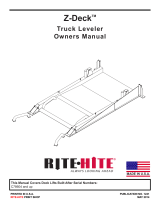
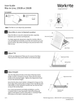
A. The i-COMM controls all functions of the door.
B. Label inside control box that is a ready reference to
the i-COMM inputs and outputs, Page 21.
C. Incoming power terminals L1, L2, L3, ground.
D. Green bold dashed line indicates safe area for
drilling holes.
E. Red bold solid line indicates un-safe area for drilling
holes
F. Illuminated input Led’s.
G. Illuminated output Led’s.
H. Serial number label.
20 Publication: AMEN00041 2017-11-06
TRAKLINE™ MODEL 8910 ROLL / 8920 FOLD Installation/Owner’s Manual Rite-Hite®
ELECTRICAL INSTALLATION
T1
- CONTROLLER LOGIC -
INPUTS & OUTPUTS ON CONTROLLER
R
F2 F3
USE CLASS CC
FUSES ONLY
RATED 600V, 30A
USE CLASS CC
FUSES ONLY
RATED 600V, 30A
F5F4
F7
CR3
F1
STB
N
N
W
V
U
GND
F2
USE CLASS CC
FUSES ONLY
RATED 600V, 30A
USE CLASS CC
FUSES ONLY
RATED 600V, 3 0A
F5F4
F7
F1
220V 1Ø
3Ø 208, 230V, 460V
CR1
H1 H2 H3 H4
X3 X2 X1
BRK
GND
GND
STB
N
N
W
BRK
Detect
Loop sens. Adj.
5
Pres. / pulse
678910
APEMs
Entry / Ex it
Pres. / pulse
Entry / Ex it
100ms / 500ms
Relay A
Relay A
Relay B
Relay B
Pulse
Not Used
123 4
ON
Power
Freq. Adjust
Relay A,B
ASB
Act / P ass
Pres. Time Adj.
1 min to
8
12345
678910
6
24V
7
0V
8
CLSG
9
RE
10
BKWY
1
OPEN
2
CLS
3
STOP
4
O/C
5
COM
ACTIVATOR
POWER SAFETY
RF Com
Fault
Remote
Pairing
WIRELESS HOST
12-24VAC/DC
COM NO NC
ON
12
10RD433
12-24V
AC/DC
COM
NO
NC
PUL | TOG
0.5s | 10s
DELAY
NO
DELAY
POWER
HOLD
TIME
LEARN
ACT LEARN
CLASS II LOW VOLTAGE ONLY !
F2 F3
USE CLASS CC
FUSES ONLY
RATED 600V, 30A
USE CLASS CC
FUSES ONLY
RATED 600V, 30A
F5F4
F7
F1
N
N
BRK
3Ø 400V, 575V
E
E
F
AG
B
D
C
H
H
Figure 28
E
Remove labels after installation is complete
/