Page is loading ...

Installation and Operating
Handbook
V1.5
Teledyne Paradise Datacom
106 Waterhouse Lane,
Chelmsford, Essex, England, CM1 2QU
Tel: +44(0)1245 847520
Tel: +44(0)1376 515636
https://www.teledynedefenseelectronics.com/paradisedatacom
AXIOM-C
Compact Satellite Modem

AXIOM-C Compact Satellite Modem
Installation and Operating Handbook
_________________________________________________________________________________________________________________________________
Version 1.5 2 August 2023
Contents
CONTENTS ............................................................................................................................................................. 2
1. INTRODUCTION .............................................................................................................................................. 5
INTRODUCTION TO AXIOM-C ......................................................................................................................................... 5
DVB-S2(X) .................................................................................................................................................................. 5
2.GENERAL DESCRIPTION ....................................................................................................................................... 5
ISO 9001 ACCREDITATION: ............................................................................................................................................. 5
SAFETY COMPLIANCE: ..................................................................................................................................................... 5
ENVIRONMENTAL COMPLIANCE: ....................................................................................................................................... 6
ELECTROMAGNETIC COMPATIBILITY (EMC) COMPLIANCE: ..................................................................................................... 6
UNPACKING: ................................................................................................................................................................. 7
DC SUPPLY: .................................................................................................................................................................. 7
SYSTEM OVERVIEW: ....................................................................................................................................................... 7
CONNECTORS: ............................................................................................................................................................... 7
RACK MOUNT OPTIONS: ................................................................................................................................................. 8
OPERATIONAL LIMITS ...................................................................................................................................................... 8
24V DC Power Supply: ........................................................................................................................................... 8
Operating Temperature: ....................................................................................................................................... 8
BUC DC PSU ........................................................................................................................................................... 9
LNB DC PSU ........................................................................................................................................................... 9
L-Band Frequency Operation................................................................................................................................. 9
Configuration Devices: .......................................................................................................................................... 9
Ethernet connectors .............................................................................................................................................. 9
Modulator Specification: ..................................................................................................................................... 10
Demodulator Specification: ................................................................................................................................. 11
Supported Modulation and Code Rates: ............................................................................................................. 12
Router and Advanced specifications: .................................................................................................................. 12
Interface, Mechanical and Environmental Specifications: .................................................................................. 13
LED Indicators ..................................................................................................................................................... 13
Front Panel: ......................................................................................................................................................... 13
Web User Interface: ............................................................................................................................................ 13
SAF / HW options available ................................................................................................................................. 14
Standard Features ............................................................................................................................................... 16
Optional Features................................................................................................................................................ 16
3.OPERATION....................................................................................................................................................... 17
WEB USER INTERFACE: .................................................................................................................................................. 17
Carrier: ................................................................................................................................................................ 23
Service, Modulation and Coding: ........................................................................................................................ 25
Interface and Control: ......................................................................................................................................... 26
Radius AAA: ......................................................................................................................................................... 27
Notes for RADIUS Network Administrators: ........................................................................................................ 28
Open AMIP: ......................................................................................................................................................... 28
AUPC Configuration: ........................................................................................................................................... 29
Carrier loss action explained: .............................................................................................................................. 31

AXIOM-C Compact Satellite Modem
Installation and Operating Handbook
_________________________________________________________________________________________________________________________________
Version 1.5 3 August 2023
AUPC functionality: ............................................................................................................................................. 32
BUC: .................................................................................................................................................................... 32
LNB: ..................................................................................................................................................................... 33
ACM Configuration: ............................................................................................................................................ 35
Alarm Settings: .................................................................................................................................................... 36
SAF entry screens: ............................................................................................................................................... 38
SNMP configuration: ........................................................................................................................................... 39
HTTPS configuration: .......................................................................................................................................... 40
IP Mode: .............................................................................................................................................................. 40
Configuring TCP Acceleration .............................................................................................................................. 42
IP Addresses: ....................................................................................................................................................... 43
IP Miscellaneous: ................................................................................................................................................ 45
Tx IP Buffers: ....................................................................................................................................................... 48
DHCP/NAT: .......................................................................................................................................................... 50
Miscellaneous: .................................................................................................................................................... 52
MPEG2 Transport Stream: .................................................................................................................................. 53
Point-to-Multipoint Operation: ........................................................................................................................... 55
IPv4 and IPv6 Static Routes: ................................................................................................................................ 56
IPv4 Routes: ........................................................................................................................................................ 57
IPv6 Routes: ........................................................................................................................................................ 57
IPv4 Header Compression Routes: ...................................................................................................................... 57
QUICK START GUIDE: .................................................................................................................................................... 58
Modem quick Setup menus: ................................................................................................................................ 58
Create New Configuration: ................................................................................................................................. 60
Upload New Configuration: ................................................................................................................................ 60
Reversionary Control: .......................................................................................................................................... 61
Memories List: ..................................................................................................................................................... 62
SW upgrade: ....................................................................................................................................................... 63
SW upgrade via USB: .......................................................................................................................................... 63
Time: ................................................................................................................................................................... 64
NTP: ..................................................................................................................................................................... 64
Reset: .................................................................................................................................................................. 64
4.STATUS ............................................................................................................................................................. 65
VIEW MODEM STATUS: ................................................................................................................................................. 65
Setup: .................................................................................................................................................................. 65
Traffic: ................................................................................................................................................................. 65
Demodulator: ...................................................................................................................................................... 66
Unit: .................................................................................................................................................................... 67
SAF: ..................................................................................................................................................................... 67
............................................................................................................................................................................ 68
Ethernet Port Status: ........................................................................................................................................... 68
VIEW GRAPHS: ............................................................................................................................................................ 69
Spectrum Graph: ................................................................................................................................................. 69
Constellation Graph: ........................................................................................................................................... 70
Time Series Charts: .............................................................................................................................................. 71
IP port Charts: ..................................................................................................................................................... 72
ACM Graphs: ....................................................................................................................................................... 73

AXIOM-C Compact Satellite Modem
Installation and Operating Handbook
_________________________________________________________________________________________________________________________________
Version 1.5 4 August 2023
MODEM UTILITIES: ....................................................................................................................................................... 73
Alarms: ................................................................................................................................................................ 73
Log: ..................................................................................................................................................................... 74
5.TROUBLESHOOTING .......................................................................................................................................... 74
Test: .................................................................................................................................................................... 74
BERT: ................................................................................................................................................................... 75
Resetting to Defaults: ......................................................................................................................................... 76
Fault and warning descriptions: .......................................................................................................................... 76
Glossary: ............................................................................................................................................................. 78

AXIOM-C Compact Satellite Modem
Installation and Operating Handbook
_________________________________________________________________________________________________________________________________
Version 1.5 5 August 2023
1. Introduction
Introduction to AXIOM-C
The AXIOM-C is a compact, powerful, IP centric satellite modem, supporting L2 Bridging and L3 routing.
Designed for simple integration into standard 1U 19 inch racks (two can fit side by side) or particularly
suited to where space is at a premium such as remote terminals, man packs, vehicles, ships and aircraft,
designed for portable communications and communications on-the-move. Physically small with low
power consumption the Modem is compatible with our QFlex-400, QMultiFlex-400 and other AXIOM
modems within the series. Although physically small this does not limit performance as the AXIOM-C is
capable of supporting up to 575Mbps of aggregate data throughput and in excess of 160,000 IP packets
per second.
DVB-S2(X)
The AXIOM-C supports the most powerful, spectrally efficient Modulation and coding available: DVB-S2
and DVB-S2X. Where DVB-S2X extends the MODCOD range up to 256APSK rate 3/4, providing 6.0 Bit’s/Hz
for a decoding threshold of 19.57 dB. This extended range may be exploited by broadband applications
on modern high-throughput satellites (HTS).
DVB-S2X Increases the granularity in modulation and coding (MODCODs). Compared to the coarse
MODCODs available in DVB-S2 that provide roughly 1 dB granularity in decoding threshold, DVB-S2X
MODCODs are typically only 0.3 to 0.5 dB apart. This allows selecting a MODCOD that more precisely fits
the link characteristics, reducing unnecessary margins and providing better throughput. This is especially
so when utilising Adaptive Coding and Modulation (ACM).
2.General Description
ISO 9001 Accreditation:
Teledyne Paradise datacom conforms to ISO 9001, the international standard that specifies requirements
for a quality management system (QMS). Organizations use the standard to demonstrate the ability to
consistently provide products and services that meet customer and regulatory requirements.
UKAS is the national accreditation body for the United Kingdom and assess businesses against
internationally agreed standards.
Safety Compliance:
To ensure operator safety, this AXIOM-C satellite modem conforms to the provisions of EMC Low Voltage
Directive 2006/95/EC and complies with the following standard:

AXIOM-C Compact Satellite Modem
Installation and Operating Handbook
_________________________________________________________________________________________________________________________________
Version 1.5 6 August 2023
• EN 62368-1: 2014 Edition 2. Safety requirements for Audio/video, information and
communication technology equipment.
Prior to installation and at all points during operation the following points must be observed.
Environmental Compliance:
All Teledyne Paradise Datacom satellite modem products are compliant with the following EC
environmental directives:
• The Reduction of Hazardous Substances (RoHS) Directive 2011/65/EU.
• The Waste Electrical and Electronic Equipment (WEEE) Directive 2012/19/EU.
The equipment should not be directly connected to the Public Telecommunications Network.
Operation of the equipment in an environment other than that stated will invalidate the safety standards.
____________________________________________________________________________________
WARNING: The equipment must not be operated in an environment in which it is exposed to any of the
following:
• Unpressurised altitudes greater than 3000 meters.
• Extreme temperatures outside the stated operating range.
• Excessive dust.
• Moisture or humid atmosphere above 95% relative humidity.
• Excessive vibration.
• Flammable gases.
• Corrosive or explosive atmosphere.
Electromagnetic Compatibility (EMC) Compliance:
This satellite modem conforms to the provisions of EMC Directive 2004/108/EC and complies with the
following EC and FCC standards:
• Emissions: EN 55032:2015 Class A – ‘Information Technology Equipment – Radio
Disturbance Characteristics – Limits and Methods of Measurement’.
• Immunity: EN 55035:2017 ‘Information Technology Equipment – Immunity Characteristics –
Limits and Methods of Measurement’.
• Federal Communications Commission (FCC) Federal Code of Regulation Part 15, Subpart B.
Connections to transmit and receive L-Band interfaces must be made with double-screened coaxial cable
(for example, RG223/U).
The modem Ethernet ports should not be connected directly to outdoor Ethernet cables that may be
subject to transient over-voltages due to atmospheric discharges and faults in the power distribution

AXIOM-C Compact Satellite Modem
Installation and Operating Handbook
_________________________________________________________________________________________________________________________________
Version 1.5 7 August 2023
network. Instead, the modem should be connected via an Ethernet switch or router to provide isolation
from over-voltages as recommended within EN 61000-3-2:2014 class A.
Unpacking:
Prior to unpacking, inspect the exterior of the shipping container for any signs of damage during transit.
If damage is evident, please contact the carrier with a view to submitting a damage report.
Carefully unpack the AXIOM-C, taking care not to discard any packing materials as this can be used for
storage and further shipment. In addition, should the need arise for the unit to be returned to Teledyne
Paradise Datacom then it is recommended that the original packing carton is used as it is designed to
provide the necessary level of protection during shipment.
Once unpacked, visually inspect the AXIOM-C to ensure there are no signs of damage.
DC Supply:
This satellite modem is classified by EN 61000-3-2:2014 class A safety standard as a ‘Pluggable Equipment
Type A’. A regulated 24V DC power supply must be used and is supplied with the unit. Typical power
consumption is 25W; typical maximum power consumption is 30W.
The installation of the satellite modem and the connection to the power supply must be made in
compliance with local and national wiring regulations for a Category II ‘impulse over-voltage’ installation.
The satellite modem should allow a convenient means of disconnection from the line supply.
________________________________________________________________________________
WARNING: This satellite modem requires the use of a regulated 24V power supply that provides
a line conductor and ground connection (i.e. it’s not a floating input). The power system must have a
direct ground connection.
Teledyne Paradise Datacom maintains a program of continuous product improvement and reserves the
right to change specifications without prior notice.
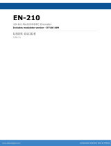
System Overview:
Connector Positions & PSU
Connectors:
24V DC Connector: A four pin DIN connector is the interface for the 24V input power supply.
Ethernet Connectors: Four Gigabit Ethernet RJ45 connectors are provided for modem Monitor and
Control (M&C) and satellite traffic.
Tx SMA: The L-Band transmit interface connector.

AXIOM-C Compact Satellite Modem
Installation and Operating Handbook
_________________________________________________________________________________________________________________________________
Version 1.5 8 August 2023
Rx SMA: The L-Band receive interface connector.
USB 3 Connector: (Front panel) Used to upgrade the unit’s software, upload or download configurations,
provides a WiFi connection when a suitable dongle is connected.
Rack Mount Options:
Various rack mount fixing kits are available, which allow the units to be fixed to a variety of rack sizes:
K4100 19” rack mount kit (2 X half width)
K4101 9.5” rack mount kit
K4102 10.5” rack mount kit
K4103 19” rack mount kit
Operational limits
24V DC Power Supply:
The modem is designed to operate from a regulated +24V DC supply. There is no further regulation of the
24V provided on the circuit board itself and therefore we recommend a +24V DC +/- 0.5 volts power supply
is used, although the unit will operate with +/- 5% tolerance with power considerations, for example the
power dissipation goes up several Watts at the high end. There is a four-way DIN terminal provided for
connecting to the PSU, which is supplied as standard with the unit.
Operating Temperature:
The modem operating temperature range is 0°C to +50°C. Temperature is measured on the surface of the
main PCB, which will typically be hotter than the ambient temperature inside the enclosure by around
20°C. It is the ambient temperature that is central to correct operation, not the reported surface
temperature. Consequently, the following operator warnings and faults are raised:
45°C operation: the modem reports 67°C, where the unit will raise a temperature warning alarm.
50°C operation: the modem reports 72°C, where the unit will raise a temperature fault alarm and mute
the transmit carrier.
5°C operation: the modem reports 30°C, where the unit will raise a temperature warning alarm.
0°C operation: the modem reports 25°C, where the unit will raise a temperature fault alarm and mute the

AXIOM-C Compact Satellite Modem
Installation and Operating Handbook
_________________________________________________________________________________________________________________________________
Version 1.5 9 August 2023
transmit carrier.
By default, the transmit carrier is muted when a temperature alarm occurs. The system designer is
responsible for controlling the temperature rise external to the unit to ensure the above limits are
adhered to for correct Modem operation.
BUC DC PSU
The standard 24V DC power supply is only suitable for providing power to the Modem. If powering a Block
Up Converter (BUC) via the IFL, then the optional high capacity power supply unit is required. This can
source a maximum of 4 amps at 24V. In addition, a BUC power supply SAF is also required.
___________________________________________________________________________________
WARNING: It is highly recommended that 10MHz, DC and carrier services are Switched off prior
to disconnecting or connecting the modem L-band RF cables in order to avoid potential for damage.
____________________________________________________________________________
LNB DC PSU
The AXIOM-C primary power supply may be used to provide DC to a Low Noise Block-downconverter, this
can be set to, 13V, 15V, 18V or 20V at a maximum current of 0.5A via the Rx IFL. In addition, 22kHz control
can be enabled, which allows a suitable LNB to operate over the entire Ku frequency band by switching
the LO from 9.75 to 10.6 GHz. The LO switching is achieved either by changing voltage from 13V to 18V or
by sending a 22kHz tone.
__________________________________________________________________________________
WARNING: It is highly recommended that DC is switched off to the LNB prior to disconnecting or
connecting the modem L-band RF cables in order to avoid potential for damage. Note: When disabled,
a residual voltage of <0.5v is present on Rx port connector.
___________________________________________________________________________
________________________________________________________________________
L-Band Frequency Operation
The unit supports L-band operation, via transmit and receive SMA connectors, supporting 50Ω operation
from 950 to 2150MHz with 1Hz step size. A high-stability L-band 10MHz reference signal for output to a
Block Up Converter (BUC) can also be enabled to phase-lock the BUC’s local oscillator to a highly stable
frequency reference.
Configuration Devices:
The AXIOM-C operates without requiring an LCD front panel display. The configuration, monitoring and
control is via an intuitive Ethernet based web browser that can be operated via a tablet, Mobile or laptop
PC and allows the user to configure and monitor the Modem from any suitable device. In addition, WiFi
capability further enhances the ease of use and provides greater flexibility for remote control and
installation using portable devices.
The latest editions of major browsers are supported, for example Chrome, Firefox, Edge, iOS and Android.
For smaller devices, graphs / overview pages may have alternative views and appropriate text warnings
regarding device orientation, where a more suitable view can be obtained, are displayed.
Ethernet connectors
Four Gigabit Ethernet RJ45 connectors are provided for modem Monitor and Control (M&C) and satellite
traffic. Ethernet speed, duplex and cable termination (crossover versus straight-through) are auto-

AXIOM-C Compact Satellite Modem
Installation and Operating Handbook
_________________________________________________________________________________________________________________________________
Version 1.5 10 August 2023
negotiated. Line speed and duplex can also be set to fixed values. The Ethernet ports can be bridged
together under software control. However, initially the M&C port is not bridged to the traffic ports and so
only the M&C port is available for the web user Interface (and the other ports support IP satellite traffic).
When the M&C port is bridged to the other ports then M&C and traffic can be passed using any port.
These provide a combined 160,000 packets-per-second processing capability and up to 575Mbps of
aggregate throughput over satellite.
RJ45 Ethernet Port Functions
M&C control can be via the Simple Network Management Protocol (SNMP), an embedded web server that
sends web pages to a web browser, a Telnet-style terminal emulation application or via TCP packets that
encapsulate Paradise Universal Protocol (PUP) commands.
A dual IPv4/IPv6 TCP/IP stack is provided. IPv4 support is provided for all IP functions as the default. With
respect to IPv6, bridging and routing are supported along with an IPv6 embedded web server. Modem IP
addresses and static routes can also be entered and displayed in IPv6 format.
MTU: The Maximum Transmission Unit size is 10,000 bytes. This defines the largest Ethernet frame that
can be supported by the modem in bridging mode, without fragmenting the Ethernet frames into smaller
frames.
M&C VLAN: M&C traffic destined for the modem at the other end of the link can be transmitted in a
special VLAN. When enabled, all M&C traffic destined for the far end is sent over satellite using VLAN 0.
The M&C packets will be received and processed by the modem at the other end of the link when the
equivalent control is enabled on that modem.
This technique for remote control means that the M&C port does not need to be bridged to the traffic
port(s) thereby facilitating the use of separate M&C and traffic networks that use different subnets.
Modulator Specification:
The transmit baseband digital circuit encodes terrestrial IP traffic presented to the modem on the
Ethernet ports into satellite frames and generates in-phase (I) and quadrature (Q) digital signals that are
passed to high speed digital-to-analogue converters. The analogue I and Q signals are then presented to
an analogue modulator along with a local oscillator at the required RF frequency, this generates the
modulated signal to be transmitted to satellite.
Function
Description
Modulator
DVB-S2: QPSK, 8PSK & 16APSK
DVB-S2X: QPSK, 8PSK, 8APSK-L 16APSK, 16APSK-L, 32APSK, 32APSK-L, 64APSK & 64APSK-L
Options for Advanced Modulation: 128APSK, 256APSK and 256APSK-L

AXIOM-C Compact Satellite Modem
Installation and Operating Handbook
_________________________________________________________________________________________________________________________________
Version 1.5 11 August 2023
Output Power
0 to –40dBm (950 to 2150MHz)
Transmit Filter Roll-off
DVB-S2: 20%, 25%, 35%
DVB-S2X: 5%, 10%, 15%, 20%, 25%, 35%
Frequency
L-band: 950 to 2150MHz (1Hz resolution)
Tx Data Rate Limits
DVB-S2/S2X: 100kbps to 345Mbps
Data Rate Options
Standard: 2Mbps
Options: 5Mbps, 10Mbps, 25Mbps, 100Mbps & 345Mbps
Tx Symbol Rate Limits
DVB-S2/S2X:100ksps to 100Msps
Harmonics & Spurious
Better than –55dBc / 4kHz in-band (at 0dBm to –30dBm output)
BUC PSU SAF Option
Allows 24V DC to power a BUC via the IFL (4A/2A Max respectively)
BUC 10MHz Reference
Via IFL cable; 10MHz ± 0.01 ppm; 2dBm ± 2dBm
Modulator Outline Specification Table
Demodulator Specification:
The received RF signal from the satellite is presented to a variable gain low noise amplifier for signal
conditioning. This is then passed to a DVB-S2X satellite ASIC that demodulates and decodes the signal
providing a digital signal for the receive baseband circuit to generate the terrestrial IP traffic.
Tx and Rx L-Band ports are fitted with 50Ω SMA connectors as standard.
The carrier signal level at the input of the modem must be in the following range:
Minimum signal level: -140 +10 log (symbol rate) dBm
Maximum signal level: -78 + 10 log (symbol rate) dBm
The maximum wanted-to-composite power level that is supported with no implementation loss is defined
by the equation:
Maximum wanted-to-composite power level: -102 + 10 log (symbol rate) dBm
The maximum input power level is -3dBm.
Function
Description
Demodulator
DVB-S2: QPSK, 8PSK & 16APSK
DVB-S2X: QPSK, 8PSK, 8APSK-L 16APSK, 16APSK-L, 32APSK, 32APSK-L, 64APSK & 64APSK-L
Options for Advanced Modulation: 128APSK, 256APSK and 256APSK-L
Transmit Filter Roll-off
DVB-S2: 20%, 25%, 35%
DVB-S2X: 5%, 10%, 15%, 20%, 25%, 35%
Frequency
L-band: 950 to 2150MHz (1Hz resolution)
Rx Data Rate Limits
DVB-S2/S2X: 100kbps to 230Mbps
Rx Data Rate options
Standard: 2Mbps
Options: 5Mbps, 10Mbps, 25Mbps, 100Mbps & 230Mbps
Rx Symbol Rate Limits
DVB-S2/S2X:100ksps to 100Msps (85Msps@ 8PSK/8APSK, 64Msps@ 16APSK, 51Msps @ 32APSK,
43Msps @ 64APSK, 36Msps @ 128APSK, 32Msps @ 256APSK)

AXIOM-C Compact Satellite Modem
Installation and Operating Handbook
_________________________________________________________________________________________________________________________________
Version 1.5 12 August 2023
Input Range
Minimum: -140 + 10 log (symbol rate)
Maximum: -78 + 10 log (symbol rate)
LNB Voltage
Selectable 13V, 15V, 18V or 20V DC to LNB via IFL cable; maximum 0.5A
22kHz Tone
LO control, allows a Ku Band LNB to be switched from low to high band or vice versa
Demodulator Outline Specification Table
The following table lists the DVB-S2 and DVB-S2X Modulations and code rates supported. These are for
Short and Normal FEC frame sizes (16,200 bits and 64,800 bits respectively). Both are supported unless
otherwise stated. (Note: DVB-S2, 32APSK is available when DVB-S2X is purchased and so is not available
when the low-cost DVB-S2 option only is purchased.)
Supported Modulation and Code Rates:
Function
Description
DVB-S2
QPSK: 1/2, 2/3, 3/4, 1/4, 1/3, 2/5, 3/5, 4/5, 5/6, 8/9 & 9/10
8PSK: 2/3, 3/4, 3/5, 5/6, 8/9 & 9/10
16APSK: 2/3, 3/4, 4/5, 5/6, 8/9 & 9/10
32APSK: 3/4, 4/5, 5/6, 8/9 & 9/10
DVB-S2X
Short Frames
All available DVB-S2 Modulations and code rates plus:
QPSK: 11/45, 4/15, 14/45, 7/15, 8/15 & 32/45
8PSK: 7/15, 8/15, 26/45 & 32/45
16APSK: 7/15, 8/15, 26/45, 3/5 & 32/45
32APSK: 2/3 & 32/45
DVB-S2X
Normal Frames
All available DVB-S2 Modulations and code rates plus:
QPSK: 13/45, 9/20 & 11/20
8PSK: 23/36, 25/36 & 13/18
16APSK: 26/45, 3/5, 28/45, 23/36, 25/36, 13/18, 7/9 & 77/90
32APSK: 32/45, 11/15 & 7/9
64APSK: 4/5, 5/6, 11/15 & 7/9
128APSK: 3/4 & 7/9
256APSK: 3/4 & 32/45
DVB-S2X-L
Normal Frames
(see note*)
8APSK: 5/9-L & 26/45-L
16APSK: 1/2-L, 8/15-L, 5/9-L, 3/5-L & 2/3-L
32APSK: 2/3-L
64APSK: 32/45-L
256APSK: 2/3-L, 29/45-L, 31/45-L & 11/15-L
MODCOD’s Supported
Note*MODCODs optimised for linear transponders are indicated by an `L` suffix, these are for use on
quasi-linear channels which are subject to phase noise.
Router and Advanced specifications:
Function
Description
Network Support
Layer 2 Bridging, Layer 3 Routing, Jumbo Frames to 10k bytes, up to 160,000 pps
Management
HTTP/S Web Server, SNMP v1, v2c & v3, AAA RADIUS Secure User Login & Access Control Lists, SSH, Q-

AXIOM-C Compact Satellite Modem
Installation and Operating Handbook
_________________________________________________________________________________________________________________________________
Version 1.5 13 August 2023
NET™ Navigator
Protocols
IPv4/IPv6, IEEE 802.1q /p VLAN support, Software Defined Network Support, NAT, DHCP, Network Time
Protocol (NTP), sFlow Performance Metrics, Active Queue Management (AQM), MPEG over IP,
OpenAMIP Protocol Support, Inter VLAN Routing Support with Virtual Routing & Forwarding
Advanced IP Features
Robust Header Compression (RFC 3095), Payload Compression, Dynamic Routing (RIP V1, V2; OSPF V2,
V3; BGP V4) and TCP Acceleration
DVB Features
ACM/VCM, DVB Encapsulation, GSE Encapsulation
Router and Advanced Outline Specification Table
Interface, Mechanical and Environmental Specifications:
Function
Description
Traffic Interface
4-port Gigabit Ethernet switch (RJ45 connectors; used for IP traffic and M&C)
IF Tx and Rx
L-band: 950 to 2150MHz (1Hz resolution) SMA connectors
Power Supply
Regulated 24 Volt DC input ± 0.5V
Mechanical
Size: 209mm W x 209mm D x 42.2mm H; (217mm deep including RF connectors). Lightweight: 745g
Environmental
-0°C to 50°C Operating Temperature; 95% relative humidity, non-condensing, FCC, CE and RoHS
compliant, Safety: EN 62368-1;2014 Edition 2 Emissions: EN 55032: 2015 Class A, Immunity:
EN55035:2017.
Interface Outline Specification Table
LED Indicators
Front Panel:
The front panel LED indicators have the following meaning:
Green – Unit Okay Red – Unit Fault
Green – Unit Okay Off – Rx Disabled or Rx Fault
Green – Unit Okay Off – Tx Disabled or Tx Fault
Amber – Test Enabled Off – Test Disabled
Green – Carrier Enabled Off – Carrier Disabled
Front Panel LED Functionality
Web User Interface:
The functionality of the Web User Interface LED mimic is different to the front panel display. The WUI
display has the following meaning:

AXIOM-C Compact Satellite Modem
Installation and Operating Handbook
_________________________________________________________________________________________________________________________________
Version 1.5 14 August 2023
Web User Interface LED Mimic Functionality
UNIT STATUS: RX TRAFFIC: TX TRAFFIC:
GREEN – OK/Enabled GREEN – OK/Enabled GREEN – OK/Enabled
RED – Alarm YELLOW - Alarm YELLOW - Alarm
NONE/GREY - Off/Disabled NONE/GREY - Off/Disabled NONE/GREY - Off/Disabled
TEST MODE: TX CARRIER:
YELLOW – On GREEN – OK/Enabled
NONE/GREY - Off/Disabled NONE/GREY - Off/Disabled
SAF / HW options available
Several software options, known as Software Activated Features (SAF), are available as shown in the
following Table. These can be purchased on a pay-as-you-go basis and activated in deployed units as
required, simply by entering a feature code via the modem’s Web user interface. Feature codes are
encrypted codes issued by Teledyne Paradise Datacom, uniquely associated with individual modems.
To allow evaluation of modem features, all of the SAF features of the modem that it is capable of
supporting can be activated for a 10-day period by entering a feature code of 0. This is referred to as
Demonstration Mode, or a demo test shot. Demonstration Mode can be activated up to three times after
which any further attempts to use it will be rejected. Note that it is not necessary to wait for
Demonstration Mode to time out before reactivating it: it can be activated twice to give a 20-day
demonstration period and three times to give 30 days. The user will be alerted shortly before the
demonstration period times out. As well as allowing feature evaluation, Demonstration Mode can be used
to test compatibility with other equipment and allows rapid substitution of equipment in a crisis.
To enable one or more features permanently (referred to as Permanent Mode), a modem-specific feature
code needs to be obtained from Teledyne Paradise Datacom. The code is tied to the modem serial number
(available via the user interfaces and on the back panel).
The features that have been temporarily enabled on a modem can be viewed along with the time
remaining before they become disabled, as can the features that have been permanently enabled and
those that can potentially be enabled.

AXIOM-C Compact Satellite Modem
Installation and Operating Handbook
_________________________________________________________________________________________________________________________________
Version 1.5 15 August 2023
Software Accessible Features (SAF) available within the Modem
The SAF function keeps the initial cost of a modem to the minimum and allows simple field upgrading at
a later date, as required.
In the table, the SAF Code column lists the acronyms by which features are referred to on the modem’s
Web user interface. Each AXIOM-C has DVB-S2 features enabled as standard, supporting QPSK, 8PSK and
16APSK.
SAF Code
Description
Tx Path
Enables Transmit path
Rx Path
Enables Receive path
Tx Data Rate 5
Enables Transmit data rates between 100kbps and 5Mbps
Tx Data Rate 10
Enables Transmit data rates between 100kbps and 10Mbps
Tx Data Rate 25
Enables Transmit data rates between 100kbps and 25Mbps
Tx Data Rate 100
Enables Transmit data rates between 100kbps and 100Mbps
Tx Data Rate 340
Enables Transmit data rates between 100kbps and 340Mbps
Rx Data Rate 5
Enables Receive data rates between 100kbps and 5Mbps
Rx Data Rate 10
Enables Receive data rates between 100kbps and 10Mbps
Rx Data Rate 25
Enables Receive data rates between 100kbps and 25Mbps
Rx Data Rate 100
Enables Receive data rates between 100kbps and 100Mbps
Rx Data Rate 230
Enables Receive data rates between 100kbps and 340Mbps
DVB-S2X
Enables DVB-S2X Modulations and Code Rates
128/256
Enables Advanced Modulations, supporting 128/256APSK
Compression
Enables Header and Payload Compression:
Header Compression Enables Ethernet, TCP, UDP, IP and RTP packet header
compression
Payload Compression Enables TCP and UDP payload compression compliant to RFC
1951
Acceleration
Enables TCP acceleration. Acceleration of TCP data over satellite, supported to the
prevailing data rate of the modem
BUC
Enables the BUC PSU software feature to provide DC via the IFL to power a BUC
Pre-distorter
Tx adaptive pre-distorter, providing up to 2dB compensation for linear and non-
linear distortion in the channel.
Encryption
AES 256-bit key encryption of IP packets. (Encryption is export controlled technology
and is provided on the AXIOM-C Encryption model only.)

AXIOM-C Compact Satellite Modem
Installation and Operating Handbook
_________________________________________________________________________________________________________________________________
Version 1.5 16 August 2023
Software Accessible Features Table
Standard Features
Function
Description
Data Rate
100kbps to 2.048Mbps
DVB-S2 Tx / Rx
QPSK, 8PSK & 16APSK, CCM/ACM, 20%, 25%, 35% Roll off
Ethernet Interface
4-port Gigabit Ethernet switch for M&C and traffic
RF Interface
L-band, 950 to 2150MHz
10MHz Reference
high-G 10MHz reference (with G sensitivity rating of 1 x10⁻⁹/g)
AUPC
Automatic Uplink Power Control
Traffic Shaping
Supports CIR/BIR/priority settings for IP streams classified by IP address, Diffserv class, IEEE 802.1p
priority tag, MPLS EXP field and VLAN ID
Dynamic Routing
RIP, OSPF and BGP
Standard Features Table
Optional Features
Function
Description
Tx Data Rate Options
5Mbps data rate, extends Base operation to 5Mbps
10Mbps data rate, extends 5Mbps operation to 10Mbps
25Mbps data rate, extends 10Mbps operation to 25Mbps
100Mbps data rate, extends 25Mbps operation to 100Mbps
345Mbps data rate, extends 100Mbps operation to 345Mbps
Tx Data Rate Options
5Mbps data rate, extends Base operation to 5Mbps
10Mbps data rate, extends 5Mbps operation to 10Mbps
25Mbps data rate, extends 10Mbps operation to 25Mbps
100Mbps data rate, extends 25Mbps operation to 100Mbps
230Mbps data rate, extends 100Mbps operation to 230Mbps
Advanced IP Features
Header Compression: IP/UDP/TCP/RTP packet header compression (RFC 3095) plus Ethernet header
compression.
Payload Compression: TCP/UDP packet payload compression using the Deflate algorithm
TCP Acceleration: Up to 10,000 concurrent accelerated TCP connections to 100Mbps subject to
prevailing data rate limits
DVB-S2X Tx / Rx
DVB-S2X CCM, ACM, VCM: QPSK, 8PSK, 8APSK, 16APSK, 32APSK & 64APSK Tx operation per EN 302
307-2. Includes 5%, 10%, 15%, 20%, 25% & 35% spectral roll-offs. Includes DVB features; IP-over-
DVB encapsulation.
Advanced Modulation
DVB-S2X Advanced Modulations: 128APSK, 256APSK, 256APSK-L
Optional Features Table

AXIOM-C Compact Satellite Modem
Installation and Operating Handbook
_________________________________________________________________________________________________________________________________
Version 1.5 17 August 2023
3.Operation
Web User Interface:
The modem includes an embedded web server that allows full monitoring and control of the modem via
a web browser (on port 80). Secure connections via HTTPS (on port 443) are also supported. Non-secure
connections via HTTP (port 80) can optionally be disabled.
The following browsers are supported: Chrome, Firefox, Edge, iOS and Android, these allow access from
a PC / laptop and also via a Mobile or tablet.
To connect to the modem from a PC or laptop, ensure an Ethernet cable is connected to the Remote M&C
RJ45 socket on the rear of the modem. However, if using WiFi ensure the dongle is plugged into the
Modems USB port and search on your device for the AXIOM-C network signature. The default, factory set
M&C details are as follows:
IP address / subnet mask: 10.0.70.1 / 24
Ensure the device being used to browse to the AXIOM-C is within this subnet range and has a unique IP
address, for example 10.0.70.2 / 24. Enter the modem’s IP address into the web browser address bar. The
following login screen will be displayed and the browser will then request a username and password. The
default user names and password are as follows:
username: admin
password: paradise
Web Browser login screen
The Modems web server will load displaying the following Home screen:

AXIOM-C Compact Satellite Modem
Installation and Operating Handbook
_________________________________________________________________________________________________________________________________
Version 1.5 18 August 2023
Web Browser Home screen
It is recommended that passwords are changed from their default values. Selecting change password
within the browser session allows the user to access the password change screen.
Password Change
The new password requires entering twice. When entered, the login details are sent in an encrypted form
back to the modem.

AXIOM-C Compact Satellite Modem
Installation and Operating Handbook
_________________________________________________________________________________________________________________________________
Version 1.5 19 August 2023
Password Change entry screen
Selecting the appropriate Home screen tab allows the user to navigate through any of the associated
menus, for example selecting Tx, Rx or Modem allows the configuration associated with each group to be
accessed. Status information, displayed in a graphical format can also be obtained, for example Es/No or
Receive power, within the Signal menu. Alarms, faults and warnings can be accessed from the Alerts
menu.
Note: Access Control Lists: The user can setup access control lists to control which IP addresses can access
the modem. This can be from an individual IP address or a range of IP addresses from a particular subnet.
Please contact Paradise technical support for more information.

AXIOM-C Compact Satellite Modem
Installation and Operating Handbook
_________________________________________________________________________________________________________________________________
Version 1.5 20 August 2023
Selecting Network allows the M&C IP address and subnet mask to be changed to a suitable address for
interoperating with other network devices, or the corporate LAN.
Network screen
Update the M&C IP address and Subnet Mask, then commit the changes using the Green Submit button
at the base of each section. Prior to submitting an entry no action will be taken. If you wish to return to
the previous setting (and the Submit button has not been used) selecting cancel will return the fields to
the values populated with the previous entered data. Similarly, selecting the icon: will undo the
change, returning the field to the previous setting. Changes can be entered and submitted at the
same time or individually. An IP traffic address is not required when operating in Ethernet bridging modes.
Return Home
From any menu, selecting the Home button, circled above, will return the browser to the Home screen.
Detailed Home Screen access
Similarly, selecting the three lined column circled above, presents the user with a more detailed
Home screen, allowing individual configuration and monitoring functions to be directly accessed.
/