Page is loading ...

Outdoor Vent Kit Installation and Instruction Manual
Do not connect electrical power to the unit until all electrical
wiring has been completed.
1. National Electrical Code
2. National Fuel Gas Code
3. In Canada, CSA C22.1 Canadian Electrical Code
Part 1, and CGA No. B149.1 (latest version)
4. Local, state, provincial, and national codes, laws,
regulations, and ordinances.
5. In the State of California: The water heater must
be braced, anchored, or strapped to avoid moving
during an earthquake. Contact local utilities for
code requirements in your area or call 866-766-7489
and request instructions.
6. In the Commonwealth of Massachusetts:
a. Outdoor units may be used for summer use only.
b. The water heater may be used for hot
water heating only and may not be used in a
combination of domestic and space heating.
Installation Must Comply With
T
his water heater must be installed by a qualied and licensed personnel. The installer should be guided by
the instructions furnished with the water heater, and by local codes and utility company requirements.
CAUTION
Important
This manual is intended to be used in conjunction with
other literature provided with the water heater.
This manual includes all related control information.
It is important that t
his manual, all other documents
included in this system, and additional publications
including the Code for the Installation of Heat Producing
Appliances (latest version), be reviewed in their entirety
before beginning any work.
Installation should be made in accordance with the
regulations of the Authority Having Jurisdiction,
local code authorities, and utility companies which
pertain to this type of water heating equipment.
The actual input rate may be lower than the value listed
on the rating label due to the additional restriction on
the intake and exhaust when this kit is installed.
This installation manual includes information specific to outdoor water
heater installations. This information is meant to replace the venting
section included in the tankless water heater installation manual.
The tankless water heater installation manual includes instructions
that will be necessary for the proper installation of all other functions,
such as water and gas piping, wall mounting, control programming, etc.
Failure to follow these instructions could result in substantial property
damage, severe personal injury, or death. This installation shall be done
by a qualified service agency in accordance with these instructions, all
applicable codes, and requirements of the authority having jurisdiction.
Failure to follow these instructions could result in substantial property
damage, severe personal injury, or death.
WARNING
Note:
The manufacturer reserves the right to make changes or updates without notice and will not be held liable for errors in
literature.
PLEASE KEEP ALL INSTRUCTIONS FOR FUTURE REFERENCE.
Applicable for Professional Prestige/Performance Platinum/Encore series only.
KIT # RTGH-RHX
Rev.05/18

2
5.2"[133mm]
17.3"[440mm]
28.6"[728mm]
32.7"[832mm]
16.1"[410mm]
8.8"[224mm]
2.6"[67mm]
6.8"[173mm]
3.2"[81mm]
9.8"[250mm]
13.6"[346mm]
2.4"[60mm]
5.6"[142mm]
6.1"[156mm]
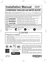
Part Shape Q’ty
① Outdoor Vent Cap
(w/ Plate and Packing)
1
② Exhaust Pipe
1
③ Exhaust Pipe
Stopper
1
④ Exhaust Adapter
(w/ P75 O-ring and
Packing)
1
⑤ Outdoor Front
Cover
(w/ Cap, Sealing)
1
Part Shape Q’ty
⑥ Bird Screen
1
⑦ Hexagon Head with
Flange Tapping Screw
(M4 x12)
(Outdoor Vent Cap)
4
⑧ Truss Head Tapping
Screw (M4 x16)
(Bird Screen)
2
Extension Cable
9.8ft (3m)
1
Instruction Manual
1
2
1
3
5
6
4
7
8
Included Outdoor Kit
Outdoor Kit Components
Outdoor Kit Dimension
17.3"[440mm]
32.7"[832mm]
5.2"[133mm]
28.6"[728mm]

3
Outdoor Installation Location
1. Outdoor Installation Area Operating Conditions.
• Ensure ambient temperatures are higher than 5
°F
/-15
°C
.
• Prevent the air from becoming contaminated by the products, places, and conditions listed in the
water heater installation manual.
WARNING
Carefully consider installation when determining water heater location. Please read the entire installation
manual and these instructions before attempting installation. Failure to properly take factors such as piping,
condensate removal, venting, and wiring into account before installation could result in wasted time, money,
and possible property damage, personal injury, or death.
The outdoor kit is meant for use in outdoor installations ONLY. DO NOT install the water heater with
outdoor kit indoors. Installing the water heater with outdoor kit indoors will result in improper water heater
operation and property damage, and could result in serious personal injury or death.
WARNING
Incorrect ambient conditions can lead to damage to the heating system and put safe operation at risk.
Ensure that the installation location adheres to the information included in this manual. Failure to do so
could result in property damage, serious personal injury, or death. Failure of heater or components due to
incorrect operating conditions IS NOT covered by product warranty.
The water heater must be installed as described in these instructions: Upright, with the suppled outdoor
enclosure in the vertical position. DO NOT attempt to install the water heater in any other orientation. Failure
to follow these instructions will result in improper water heater operation and property damage, and could
result in serious personal injury or death.
2. Check for nearby connections to:
• System water piping
• Venting connections
• Gas supply piping
• Electrical power
• Condensate drain
Note:
The manufacturer reserves the right to make changes or updates
without notice and will not be held liable for errors in literature.
Install the water heater where any leakage from the relief valve, related piping, tank, or connections will not
result in damage to surrounding areas, lower oors of the building, or pool on the ground and freeze.
The water heater should be located near a drain or piped to a drain. Leakage damages ARE NOT covered
by warranty.
CAUTION

4
3. Check surroundings of water heater.
Remove any combustible materials, gasoline, and other ammable liquids.
WARNING
Failure to keep the water heater area clear and free of combustible materials, liquids, and vapors can result in
substantial property damage, severe personal injury, or death.
4. If the water heater is to replace an existing heater, check for and correct any existing system problems, such
as:
• System leaks
• Location that could cause the system and heater to freeze and leak
• Incorrectly sized expansion tank
5. Clean and ush system when reinstalling a heater.
Do not connect the water heater to any heating systems or components that have been previously used for
nonpotable applications. Do not introduce toxic chemicals, such as antifreeze or water heater treatments,
into the water heater or any piping meant for potable purposes. Ensure that all piping and components
connected to the water heater are suitable for potable water applications. Do not use this water heater for
space heating applications.
CAUTION
The water heater must be installed level in order for the condensate to properly flow out the collection
system.
CAUTION
Installation Clearances
Outdoor Installation Clearances
[ Table 1 ]
Minimum
Clearances
Installation Clearances
from Non-Combustibles
Recommended Service
and Proper Operation
Clearances
Top of appliance 36 in (900mm)
Back of appliance 5/8 in (15.9mm)
Front of appliance 24 in (609.6mm) 24 in (609.6 mm) or more
Side of appliance 6 in (150mm)
Bottom of appliance 12 in (304.8mm)
Note:
The outdoor enclosure for this appliance
is approved for zero clearance to
combustible construction.
If the water heater is installed in a
narrow space or corner ensure that there
is sufcient space for service.
In multiple water heater installations,
ensure a minimum clearance of 36" from
the top of one water heater to the bottom
of the next water heater, and a minimum
clearance of 6" from the side of water
heater to the next water heater.

5
WARNING
Do not locate the water heater where exposed to prevailing winds.
Moisture will be produced by the exhaust vent. Take precautions when determining water heater location.
Moisture may fall from the vent termination to the ground and turn to ice in freezing conditions. Moisture or
ice can produce a hazardous condition.
Exhaust condensate is acidic and could deteriorate the surface below the exhaust vent termination.
Ensure this surface is in good repair (sealed, painted, etc.) to prevent deterioration. Failure to follow these
instructions could result in substantial property damage, serious personal injury, or death.
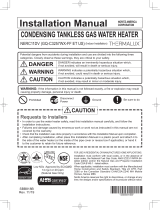
Prevent Combustion Air Contamination
Do not install the outdoor water heater in locations that
can allow contamination of fresh intake air.
Note:
See Table 2 to prevent combustion air
contamination.
•FrontClearancefromWall
•ClearancefromHandrailwithCommonSideCorridor
36"[900mm]
or more
6"[150mm]
or more
24"[600mm]
or more
47"[1,190mm]
or more
84"[2,130mm]
Common side Corridor
Handrail
•ClearancefromHandrailonBalcony
Handrail
Balcony
24"[600mm]
or more
•ClearancefromWallandCeiling
6"[150mm]
or more

6
WARNING
Ensure that the intake air will not contain any of the contaminants in Table 2. Contaminated air will damage
the heater, resulting in possible substantial property damage, severe personal injury, or death. For example,
do not pipe intake air near a swimming pool or laundry facilities. These areas always contain contaminants.
Products to Avoid Areas Likely to Have Contaminants
Spray cans containing
uorocarbons
Refrigerant leaks
Dry cleaning / laundry areas and
establishments
Auto body shops
Permanent wave solutions Paint or varnish removers Swimming pools Plastic manufacturing plants
Chlorinated waxes / cleaners Hydrochloric or Muriatic acid Metal fabrication plants
Furniture renishing areas
and establishments
Chlorine-based swimming
pool chemicals
Cements and glues Beauty shops New building construction
Calcium chloride used for
thawing Refrigeration
Antistatic fabric softeners used in
clothes dryers
Refrigeration repair shops Remodeling areas
Sodium chloride used for
water softening
Chlorine-type bleaches, laundry
detergents, and cleaning solvents
Photo processing plants Garages and workshops
Adhesives used to fasten
DAMAGE TO THE HEATER CAUSED BY EXPOSURE TO CORROSIVE VAPORS IS NOT COVERED BY
WARRANTY.
(Refer to the limited warranty for complete terms and conditions.)
CAUTION
This water heater is designed to automatically prevent freezing to temperatures of 5
°F
(-15
°C
).
This freeze protection is not effective if the power fails. In order for freeze protection
to operate, the water heater must have electrical power, gas, water and the main switch must be on.
CAUTION
Freeze Protection
Note:
Damages resulting from incorrect installation or from use of products not approved by the manufacturer
ARE NOT covered by warranty.
[ Table 2 ]

7
Clearance Requirements from Vent Terminations to Building Openings
US Installations¹ Canadian Installations²
A =
Clearance above grade, veranda, porch, deck or
balcony
12 in (30 cm) 12 in (30 cm)
B =
Clearance to window or door that may be opened 4 feet (1.2 m) below or to side of opening;
1 ft (30cm) above opening
6 in (15 cm) for appliances ≤ 10,000
Btuh (3 kw), 12 in (30 cm) for
appliances > 10,000 Btuh (3 kw) and
≤ 100,000 Btuh (30 kw), 36 in (91 cm)
for appliances > 100,000 Btuh (30 kw)
C =
Clearance to permanently closed window
* *
D =
Vertical clearance to ventilated soft located above
the terminal within a horizontal distance of
2 ft (610 cm) from the center line of the terminal
* *
E = Clearance to unventilated soft * *
F = Clearance to outside corner * *
G = Clearance to inside corner * *
H = Clearance to each side of center line extended above
meter / regulator assembly
* *
I = Clearance to service regulator vent outlet *
Above a regulator within 3 ft (91 cm)
horizontally of the vertical center line of
the regulator vent outlet to a maximum
vertical distance of 15 ft (4.5 m)
J = Clearance to nonmechanical air supply inlet to
building or the combustion air inlet to any other
appliance
4 ft (1.2 m) below or to side of opening;
1 ft (30 cm) above opening
6 in (15 cm) for appliances ≤ 10,000 Btuh
(3 kw), 12 in (30 cm) for appliances
> 10,000 Btuh (3 kw) and ≤ 100,000 Btuh
(30 kw), 36 in (91 cm) for appliances
> 100,000 Btuh (30 kw)
K = Clearance to a mechanical air supply inlet 3 ft (91 cm) above if within 10 ft (3 m)
horizontally
6 ft (1.83 m)
L = Clearance above paved sidewalk or paved driveway
located on public property
7ft (2.13 m) 7 ft (2.13 m)
†
M = Clearance under veranda, porch, deck or balcony * 12 in (30 cm)
‡
¹
In accordance with the current ANSI Z223.1/NFPA 54 Natural Fuel Gas Code
²
In accordance with the current CSA B149.1, Natural Gas and Propane Installation Code
† A vent shall not terminate directly above a sidewalk or paved driveway that is located between two single family dwellings and serves both dwellings.
‡ Permitted only if veranda, porch, deck or balcony is fully open on a minimum of two sides beneath the oor. Rheem recommends avoiding this
location if possible.
*
Clearance in accordance with local installation codes and the requirements of the gas supplier. Clearance to opposite wall is 24 in (60 cm).
r
k
l
s
i
j
m
n
h
i
q
h
t
p
o
puzpklGjvyuly
kl{hps
}lu{G{lytpuhs
hpyGz|wwsGpusl{
hylhG~olylG{lytpuhs
pzGuv{Gwlytp{{lk
m
j
v
i
m
j
v
i
i

8
Installing the Outdoor Enclosure
4. Install the Exhaust Pipe Stopper using 2
screws (re-use the remaining 2 screws that
were removed in Step 1), securing the Exhaust
Pipe in place.
2. Insert the Exhaust Adapter and secure the front 2
screws (re-use the 2 screws that were removed in
Step 1)
1. Remove the Existing Exhaust Adapter by
removing the 4 screws and pulling up on the
adapter.
Existing Exhaust
Adapter
Phillips
Phillips
Exhaust
Adapter
Exhaust Pipe Stopper
3. Insert the Exhaust Pipe into the Exhaust
Adapter.
Exhaust Pipe
Phillips

9
Phillips
Phillips
A
Packing
Remove
Remove
Loosen
Loosen
5. Use a Phillips screwdriver to loosen front 2 hex
head screws and to remove back 2 hex head
screws on side of the unit. Place the Outdoor
Vent Cap on the unit. Make sure packing is
applied inside of the Outdoor Vent Cap.
7. Insert the Bird Screen into the Exhaust Pipe
and secure with 2 screws [
⑧
Truss Head Tap-
ping Screw (M4 x16)] to the Outdoor Vent Cap.
Bird Screen
6. Use a Phillips screwdriver to tighten the 4
screws [
⑦
Hexagon Head with Flange Tapping
Screw (M4 x12)] to secure the Outdoor Vent Cap.
Detail Detail
Outdoor Vent Cap
Do not overtighten. Use hand screwdrivers only.
CAUTION
Phillips
Detail A

10
8. Remove the Front Cover (with Control Panel
Window) by removing the 4 screws.
Phillips
10. Install the Outdoor Front Cover included in the kit
and secure with the 4 screws from Step 8.
Phillips
Outdoor Front
Cover
1) Turn off the power to the control panel.
Press and hold the ‘Function Button’ to enter
the ‘Installer Mode’
2) In 'Installer Mode', turn the dial button clockwise
until the display reads ‘[16:od]’.
3) Press the 'Dial Button' so 'oFF' is ashing.
(Default setting is 'oFF' and outdoor vent
function is not activated.)
4) Turn the 'Dial Button' clockwise so 'on' is ashing. (This
will active the Outdoor Vent function.)
5) Press the 'Dial Button' to save the current setting mode
and return back to ‘Installer Mode’.
9. Setting

11
Phillips
Note:
Ifyouwouldliketoplacethecontrolpanelinsideofyourhome,followtheinstruction
below.
2. Remove the Outdoor Front Cover by
removing the 4 screws.
1. Disconnect electrical power to the unit. 3. Disconnect connector on the Control Panel and
remove the Control Panel by removing the 2
screws.
5. Route the Extension Cable through the grommet at the bottom of the unit. Close the Outdoor Front
Cover with secure 4 screws.
6. Reconnect electrical power.
* Extension Cable is 9.8 ft (3m), for longer runs the cable can be extended using 18 AWG wire up to 100 ft (30 m)
4. Install the Control Panel in a desired location inside the home by using the Extension Cable
provided in the kit. * (see note below)
Phillips

Part List
No. Description No. Description
①
Outdoor Vent Cap
(w/ Plate and Packing)
⑤
Outdoor Front Cover
(w/ Cap, Sealing)
②
Exhaust Pipe
⑥
Bird Screen with Finishing
③
Exhaust Pipe Stopper
⑦
Hexagon Head with Flange Tapping Screw (M4 x12)
④
Exhaust Adapter
(w/ P75 O-ring and Packing)
⑧
Truss Head Tapping Screw (M4 x16)
/