Page is loading ...

Installation and Instruction Manual
Outdoor Vent Kit
Model LT199NXX1 / LT199PXX1
LT199NRX1 / LT199PRX1
RTGS199N1 / RTGS199X1
RTGR199N1 / RTGR199X1
WARNING
If the information in this manual is not
followed exactly, a re or explosion may
result causing property damage, personal
injury or loss of life.
Do not store or use gasoline or other
ammable vapors and liquids in the vicinity of
this or any other appliance.
WHAT TO DO IF YOU SMELL GAS
• Do not try to light any appliance.
• Do not touch any electrical switch; do not
use any phone in your building.
• Immediately call your gas supplier from a
nearby phone. Follow the gas supplier's
instructions.
• If you cannot reach your gas supplier, call
the re department.
Installation and service must be performed
by a qualied installer, service agency, or gas
supplier.
FOR YOUR SAFETY: This product must be installed and serviced by a professional service technician,
qualied in hot water boiler and heater installation and maintenance. Improper installation and/or operation
could create carbon monoxide gas in ue gases which could cause serious injury, property damage, or
death. Improper installation and/or operation will void the warranty.
AVERTISSEMENT
Assurez-vous de bien suivres les instructions
données dans cette notice pour réduire au
minimum le risque d’incendie ou d’explosion
ou pour éviter tout dommage matériel, toute
blessure ou la mort.
Ne pas entreposer ni utiliser d’essence ou ni
d’autres vapeurs ou liquides inammables
dans le à proximité de cet appareil ou de tout
autre appareil.
QUE FAIRE SI VOUS SENTEZ UNE ODEUR DE
GAZ:
• Ne pas tenter d’allumer d’appareils.
• Ne touchez à aucun interrupteur. Ne pas vous
servir des téléphones dans le bâtiment où vous
vous trovez.
• Appelez immédiatement votre fournisseur
de gaz depuis un voisin. Suivez les
instructions du fournisseur.
• Si vous ne pouvez rejoindre le fournisseur
de gaz, appelez le sservice des incendies.
L’installation et l’entretien doivent être assurés
par un installateur ou un service d’entretien
qualié
ou par le fournisseur de gaz.
Outdoor Vent Kit Manual S633100212 Rev 11/22

2
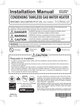
Part Shape Q’ty
⑥
Hexagon Head with Flange
Tapping Screw (M4 x12)
(Outdoor Vent Cap)
4
⑦
Philips Head Tapping
Screw (M4 x16)
(Bird Screen)
2
Instruction Manual
1
Part Shape Q’ty
① Outdoor Vent Cap
(w/ Plate and Packing) 1
② Exhaust Pipe 1
③ Exhaust Pipe Retainer 1
④
VCK Exhaust Adapter
(w/ P75 O-ring and
Packing)
1
⑤ Bird Screen 1
2
1
3
5
4
6
7
Included Items
Outdoor Kit Components Outdoor Kit Dimension
5.2" [133mm]
17.3" [440mm]
27.6" [700mm] 16.1" [410mm]
17.5" [445mm]
32.7" [832mm]

3
Outdoor Installation Location
1. Outdoor Installation Area Operating Conditions.
• Prevent the air from becoming contaminated by the products, places, and conditions listed in the water heater
installation manual.
WARNING
WARNING
2. Check for nearby connections to:
• System water piping
• Venting connections
• Gas supply piping
• Electrical power
• Condensate drain
Note:
The manufacturer reserves the right to make changes to the
installation and instruction manual without notice.
Install the water heater where any leakage from the relief valve, related piping, or connections will not result in
damage to surrounding areas, lower oors of the building, or pool on the ground and freeze.
The water heater should be located near a drain or piped to a drain. Leakage damages ARE NOT covered by
warranty.
CAUTION
Incorrect ambient conditions can lead to damage to the heating system and put safe operation at risk.
Ensure that the installation location adheres to the information included in this manual. Failure to do so could
result in property damage, serious personal injury, or death. Failure of heater or components due to incorrect
operating conditions IS NOT covered by product warranty.
The water heater must be installed as described in these instructions: Upright, with the supplied outdoor
enclosure in the vertical position. DO NOT attempt to install the water heater in any other orientation. Failure to
follow these instructions will result in improper water heater operation and property damage, and could result in
serious personal injury or death.
Carefully consider installation when determining water heater location. Please read the entire installation
manual and these instructions before attempting installation. Failure to properly take factors such as piping,
condensate removal, venting, and wiring into account before installation could result in wasted time, money,
and possible property damage, personal injury, or death.
The outdoor kit is meant for use in outdoor installations ONLY. DO NOT install the water heater with outdoor kit
indoors. Installing the water heater with outdoor kit indoors will result in improper water heater operation and
property damage, and WILL RESULT IN PERSONAL INJURY OR DEATH.

4
3. Check surroundings of water heater.
Remove any combustible materials, gasoline, and other ammable liquids.
WARNING
4. If the water heater is to replace an existing heater, check for and correct any existing system problems, such as:
• System leaks
• Location that could cause the system and heater to freeze and leak
• Incorrectly sized expansion tank
5. Clean and ush system when installing a new water heater.
Do not connect the water heater to any heating systems or components that have been previously used for
nonpotable applications. Do not introduce toxic chemicals, such as antifreeze or water heater treatments, into
the water heater or any piping meant for potable purposes. Ensure that all piping and components connected to
the water heater are suitable for potable water applications.
CAUTION
The water heater must be installed level in order for the condensate to properly ow out the collection system.
CAUTION
Outdoor Installation Clearances
[ Table 1 ]
Note:
The outdoor enclosure for this appliance
is approved for zero clearance to
combustible construction.
If the water heater is installed in a
narrow space or corner ensure that there
is sufcient space for service.
In multiple water heater installations,
ensure a minimum clearance of 32" from
the top of one water heater to the bottom
of the next water heater, and a minimum
clearance of 4" from the side of water
heater to the next water heater.
Outdoor Installation
TOP 36" (914 mm)
BACK 1
"
(25.4 mm)
FRONT 24" (610 mm)
SIDE 4
"
(102 mm)
BOTTOM 12" (305 mm)
Failure to keep the water heater area clear and free of combustible materials, liquids, and vapors can result in
substantial property damage, severe personal injury, or death.
Installation Clearances

5
Prevent Combustion Air Contamination
Do not install the outdoor water heater in locations that can allow contamination of fresh intake air.
Note:
See Table 2 to prevent combustion air contamination.
• Front Clearance from Wall
36" [914mm]
or more
or more
24" [610mm]
or more
• Clearance from Wall and Ceiling
4" [100mm]
or more
Do not locate the water heater where exposed to prevailing winds.
Moisture will be produced by the exhaust vent. Take precautions when determining water heater location.
Moisture may fall from the vent termination to the ground and turn to ice in freezing conditions. Moisture or ice
can produce a hazardous condition.
Exhaust condensate is acidic and could deteriorate the surface below the exhaust vent termination. Ensure
this surface is in good repair (sealed, painted, etc.) to prevent deterioration. Failure to follow these instructions
could result in substantial property damage, serious personal injury, or death.
WARNING
12" [305mm]

6
WARNING
DAMAGE TO THE HEATER CAUSED BY EXPOSURE TO CORROSIVE VAPORS IS NOT COVERED BY WARRANTY.
(Refer to the limited warranty for complete terms and conditions.)
CAUTION
This water heater is designed to automatically prevent freezing.
This freeze protection is not effective if the power fails. In order for freeze protection
to operate, the water heater must have electrical power, gas, water and the main switch must be on.
CAUTION
Freeze Protection
Note:
Damages resulting from incorrect installation or from use of products not approved by the manufacturer
ARE NOT covered by warranty.
Products to Avoid Areas Likely to Have Contaminants
Spray cans containing
uorocarbons Refrigerant leaks Dry cleaning / laundry areas and
establishments Auto body shops
Permanent wave solutions Paint or varnish removers Swimming pools Plastic manufacturing plants
Chlorinated waxes / cleaners Hydrochloric or Muriatic acid Metal fabrication plants Furniture renishing areas
and establishments
Chlorine-based swimming
pool chemicals Cements and glues Beauty shops New building construction
Calcium chloride used for
thawing Refrigeration
Antistatic fabric softeners used in
clothes dryers Refrigeration repair shops Remodeling areas
Sodium chloride used for
water softening
Chlorine-type bleaches, laundry
detergents, and cleaning solvents Photo processing plants Garages and workshops
Adhesives used to fasten
[ Table 2 ]
Ensure that the intake air will not contain any of the contaminants in Table 2. Contaminated air will damage
the heater, resulting in possible substantial property damage, severe personal injury, or death. For example,
do not pipe intake air near a swimming pool or laundry facilities. These areas always contain contaminants

7
Clearance Requirements from Vent Terminations to Building Openings
CSA/ANSI Z21.10.3:19 • CSA 4.3:19
Gas-fired water heaters, volume III, storage water heaters with input
ratings above 75,000 Btu per hour, circulating and instantaneous
November 2019 © 2019 CSA America Standards Inc./
© 2019 Canadian Standards Association
89
Alternatively, a separate diagram for each country is permitted to be utilized. For
clearances not specified in ANSI Z223.1/NFPA 54 or CSA B149.1, one of the following shall
be indicated:
A) a minimum clearance value determined by testing in accordance with Clause 5.17,
Wall, floor, and ceiling temperatures; or
B) a reference to the following footnote:
“Clearance in accordance with local installation codes and the requirements of the
gas supplier.”
∆Figure 2-A
Direct vent terminal clearances
(See Clauses 4.31.2 and E.1.)
X
J
A
B
B
B
B
Operable
Fixed
closed
K
Regulator vent outlet
In the event no
regulator is present,
H and I can be
disregarded.
M
AH
B
C
F
Operable
Fixed
closed X
V
V
V
VV
V
V
V
G
Inside
corner detail
B
E
D
V
Legend:
= Vent terminal
= Air supply inlet
= Area where terminal is not permitted
X
V
L
J
15 ft
Canadian installations1US installations2
A = Clearance above grade,
veranda, porch, deck, or
balcony
12 in (30 cm) 12 in (30 cm)
B = Clearance to window or door
that may be opened
6 in (15 cm) for appliances
≤ 10,000 Btuh (3 kW), 12 in
(30 cm) for appliances > 10,000
Btuh (3 kW) and ≤ 100,000 Btuh
(30 kW), 36 in (91 cm) for
appliances >100,000 Btuh
(30 kW)
6 in (15 cm) for appliances
≤ 10,000 Btuh (3 kW), 9 in
(23 cm) for appliances
> 10,000 Btuh (3 kW) and
≤ 50,000 Btuh (15 kW), 12 in
(30 cm) for appliances
> 50,000 Btuh (15 kW)
C = Clearance to permanently
closed window
As specified by the
manufacturer*
As specified by the
manufacturer*
D = Vertical clearance to ventilated
soffit located above the
As specified by the
manufacturer*
As specified by the
manufacturer*
(Continued)
Description US Non-Direct Canadian Non-Direct
A =
Clearance above grade, veranda, porch, deck, or balcony 12 in (30 cm) 12 in (30 cm)
B =
Clearance to window or door that may be opened
48 in (120 cm) below or to side of
opening; 12 in (30 cm) above opening
36 in (91 cm)
C =
Clearance to permanently closed window
* *
D =
Vertical clearance to ventilated soft located above the
terminal within a horizontal distance of 2 feet from the center
line of the termina
* *
E = Clearance to unventilated soft * *
F = Clearance to outside corner * *
G = Clearance to inside corner * *
H = Clearance to each side of center line extended above meter /
regulator assembly *
36 in (91 cm) within a height 15 ft (4.57 m)
above the meter/ regulator assembly
I = Clearance to service regulator vent outlet *
36 in (91 cm)
J = Clearance to non-mechanical air supply inlet to building or the
combustion air inlet to any other appliance
48 in (120 cm) below or to side of
opening; 12 in (30 cm) above opening 36 in (91 cm)
K = Clearance to a mechanical air supply inlet 36 in (91 cm) above if within
10 ft (3 m) horizontally 6 ft (1.83 m)
L = Clearance above paved sidewalk or paved driveway located on
public property *
7 ft (2.13 m)
M = Clearance under veranda, porch, deck or balcony *
12 in (30 cm)
Non-Direct Venting (Single Pipe) Clearances

8
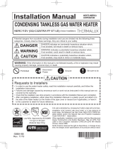
Additional Clearance
Descriptions Minimum Distances
Clearance to ventilated or unventilated soft or eve vent 36" (914 mm)
Clearance between vertical vents 60"(1,520mm)
Clearance to inside corner 12" (305 mm)
Clearance between horizontal water heaters 4" (100 mm)
Clearance under veranda, porch deck, or balcony. 12" (305 mm)
Clearance above ground 12" (305 mm)
12"(305mm) 4"(100mm)
36"(914mm)
12"(305mm)
12"(305mm)
60"(1,520mm)

9
3. Insert the Exhaust Pipe into the VCK Exhaust
Adapter.
Exhaust Pipe
4. Install the Exhaust Pipe Retainer using 2 screws
(re-use the 2 screws that were removed in Step
1), securing the Exhaust Pipe in place.
Exhaust Pipe Retainer
1. Remove the Existing Exhaust Adapter by removing
the 4 screws and pulling up on the adapter.
Existing Exhaust
Adapter
Phillips
2. Insert the VCK Exhaust Adapter and secure the
front 2 screws (re-use the 2 screws that were
removed in Step 1)
VCK
Exhaust
Adapter
Installing the Outdoor Enclosure

10
Do not overtighten. Use hand screwdrivers only.
CAUTION
5. Use a Phillips screwdriver to loosen front 2 hex
head screws and to remove back 2 hex head
screws on side of the unit. Place the Outdoor Vent
Cap on the unit. Make sure the gasket is applied
inside of the Outdoor Vent Cap.
Remove
Remove
Loosen
Loosen
6. Use a Phillips screwdriver to tighten the 4 screws
[⑥Hexagon Head with Flange Tapping Screw (M4
x12)] to secure the Outdoor Vent Cap.
Detail
7. Insert the Bird Screen into the Exhaust Pipe and
secure with 2 screws [⑦ Philips Head Tap ping
Screw (M4 x16)] to the Outdoor Vent Cap.
Bird Screen
Outdoor Vent Cap

11
③
⑥
⑥
⑤
⑦
①
②
④
No. Description Part Number No. Description Part Number
①
Outdoor Vent Cap
(w/ Plate and Packing)
⑤
Bird Screen with Finishing
②
Exhaust Pipe
⑥
Hexagon Head with Flange
Tapping Screw (M4 x12)
③
Exhaust Pipe Retainer
⑦
Philips Head Tapping Screw
(M4 x16)
④
VCK Exhaust Adapter
(w/ P75 O-ring and Packing)
Part List

Notes:
Dimensions and specications subject to change without notice in accordance with our policy of continuous product improvement.
/