Channel Vision 6210 User manual
- Category
- Security cameras
- Type
- User manual
This manual is also suitable for
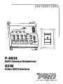
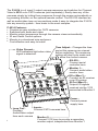
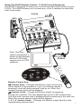
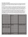
Channel Vision 6210 is a 4 input 2 output camera sequencer and switcher that is perfect for CAT5 cameras. It allows you to easily view any of the cameras by cycling through them automatically or by pressing a button on the optional remote control.
Here are some of the features of the Channel Vision 6210:
-
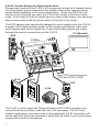
Easy to use: Simply connect your cameras to the inputs and the monitor to the output, and you're ready to go. The auto cycle mode will automatically switch between cameras, or you can use the remote control to select a specific camera.
-
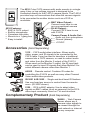
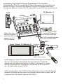
Versatile: The Channel Vision 6210 can be used in a variety of applications, from home security to commercial surveillance. It is compatible with both analog and IP cameras, and it can be controlled via RS-232 or IR remote control.
Channel Vision 6210 is a 4 input 2 output camera sequencer and switcher that is perfect for CAT5 cameras. It allows you to easily view any of the cameras by cycling through them automatically or by pressing a button on the optional remote control.
Here are some of the features of the Channel Vision 6210:
-
Easy to use: Simply connect your cameras to the inputs and the monitor to the output, and you're ready to go. The auto cycle mode will automatically switch between cameras, or you can use the remote control to select a specific camera.
-
Versatile: The Channel Vision 6210 can be used in a variety of applications, from home security to commercial surveillance. It is compatible with both analog and IP cameras, and it can be controlled via RS-232 or IR remote control.


-
 1
1
-
 2
2
-
 3
3
-
 4
4
-
 5
5
-
 6
6
-
 7
7
-
 8
8
-
 9
9
-
 10
10
-
 11
11
-
 12
12


Channel Vision 6210 User manual
- Category
- Security cameras
- Type
- User manual
- This manual is also suitable for
Channel Vision 6210 is a 4 input 2 output camera sequencer and switcher that is perfect for CAT5 cameras. It allows you to easily view any of the cameras by cycling through them automatically or by pressing a button on the optional remote control.
Here are some of the features of the Channel Vision 6210:
-
Easy to use: Simply connect your cameras to the inputs and the monitor to the output, and you're ready to go. The auto cycle mode will automatically switch between cameras, or you can use the remote control to select a specific camera.
-
Versatile: The Channel Vision 6210 can be used in a variety of applications, from home security to commercial surveillance. It is compatible with both analog and IP cameras, and it can be controlled via RS-232 or IR remote control.
Ask a question and I''ll find the answer in the document
Finding information in a document is now easier with AI
Related papers
-
Channel Vision 3112 User manual
-
-
-
-
-
-
-
-
-
Other documents
-
Essence ES800HD-OD User manual
-
 INSTAR IN-5905 User manual
-
 BBV Tx1000 Installation guide
-
Fracarro 918129 Datasheet
-
Pelco CM6800-32X6 User manual
-
-
-
-
Pelco CM6800E-48X8 User manual
-

