Page is loading ...

Installation/Operation
PelcoNet
™
Transmission System
C1977M-D (6/02)
Pelco World Headquarters • 3500 Pelco Way, Clovis, CA 93612-5699 USA • www.pelco.com
USA & Canada: Tel: 800/289-9100 • Fax: 800/289-9150
International: Tel: 1-559/292-1981 • Fax: 1-559/348-1120

[ 2 ] Pelco Manual C1977M-D (6/02)
CONTENTS
Section Page
IMPORTANT SAFEGUARDS AND WARNINGS ........................................................................................ 6
Regulatory Notices ............................................................................................................................ 6
INSTRUCTIONS FOR THE NETWORK ADMINISTRATOR ....................................................................... 7
The Transmitter and Receiver ........................................................................................................... 7
The Browser ...................................................................................................................................... 7
WHAT IS THE PELCONET TRANSMISSION SYSTEM? ........................................................................... 8
How Do LANs and WANs Work? ......................................................................................................8
Who Should Install The PelcoNet Transmission System? ................................................................ 8
OVERVIEW................................................................................................................................................. 9
Description ........................................................................................................................................ 9
Software Version ............................................................................................................................... 9
Package Contents ............................................................................................................................. 9
Front Panel Connectors .................................................................................................................. 10
Rear Panel Connectors ................................................................................................................... 11
QUICK INSTALLATION GUIDE ................................................................................................................ 12
Step 1: Connecting A Camera Or Monitor ....................................................................................... 12
Step 2: Connecting Additional Items ............................................................................................... 12
Step 3: Connecting To The LAN Port ..............................................................................................13
Step 4: Connecting Power .............................................................................................................. 13
Step 5: Selecting An IP Address For Your Network ......................................................................... 14
Step 6: Using A Web Browser To Configure The Network .............................................................. 14
Step 7: What Next? ......................................................................................................................... 14
TYPICAL APPLICATIONS ........................................................................................................................ 14
Displaying Remote Video On A Web Browser ................................................................................ 14
Displaying Video Via a Transmitter-To-Receiver Connection .......................................................... 16
Diagrams of Typical Applications .................................................................................................... 17
HARDWARE INSTALLATION ................................................................................................................... 23
Connecting Video Sources Or Displays .......................................................................................... 23
Connecting Audio Equipment .......................................................................................................... 23
Connecting Data Terminals ............................................................................................................. 24
Control Terminal Port............................................................................................................. 24
Transparent Data Port ...........................................................................................................25
Connecting External Sensors and Controlling Peripheral Devices ................................................. 26
Connecting To A LAN ...................................................................................................................... 26
CONFIGURATION .................................................................................................................................... 27
Configuration Using A Terminal Program ........................................................................................ 27
Typical Session ..................................................................................................................... 27
Command Reference ............................................................................................................ 28
Configuration Using A Web Browser ...............................................................................................29
Web Server Concept .............................................................................................................29
PelcoNet Home Page ............................................................................................................ 31
General Settings Configuration Page .................................................................................... 33
Video Settings Configuration Page ....................................................................................... 37
Audio Settings Configuration Page ....................................................................................... 40
Alarm Settings Configuration Page ....................................................................................... 42
Interface Settings Configuration Page .................................................................................. 46
LIVE VIDEO AND SERVER PUSH VIDEO PAGES.................................................................................. 48

Pelco Manual C1977M-D (6/02) [ 3 ]
WEB BROWSER CONTROL PAGES.......................................................................................................51
Accessing These Pages .................................................................................................................. 51
Controlling The Display ................................................................................................................... 52
Matrix Control Live Video/Server Push Page Contents .................................................................. 53
Genex Live Video/Server Push Page Contents .............................................................................. 54
Spectra Live Video/Server Push Page Contents ............................................................................ 55
Esprit Live Video/Server Push Page Contents................................................................................ 56
DX3016 Live Video/Server Push Control Page Contents ............................................................... 57
ADVANCED FEATURES .......................................................................................................................... 59
Automatic Connection Feature........................................................................................................ 59
Video Motion Detection Feature ...................................................................................................... 59
Alarm Notification By E-mail............................................................................................................ 59
Record and Play Back The Display On a PC .................................................................................. 60
Recording The Display .......................................................................................................... 60
Playing Back The Recording ................................................................................................. 61
Firmware Upload ............................................................................................................................. 61
TROUBLESHOOTING .............................................................................................................................. 62
Basic Functioning ............................................................................................................................ 62
Green Power LED .................................................................................................................62
LAN Link LED ........................................................................................................................ 62
Transmit LED ........................................................................................................................ 63
Terminal Program ............................................................................................................................ 63
Troubleshooting a TCP/IP Network Using A Ping Utility .................................................................. 63
Troubleshooting Connection Problems ........................................................................................... 64
Troubleshooting The Video Connection .......................................................................................... 64
Testing The Audio Connection ........................................................................................................ 64
Test Between Audio-Equipped Transmitter and Audio-Equipped Receiver ........................... 64
Test Between Audio-Equipped Transmitter and PC .............................................................. 65
DX3000 Warning Reset Button ....................................................................................................... 65
SPECIFICATIONS .................................................................................................................................... 66
GLOSSARY .............................................................................................................................................. 68
APPENDIX A – CONNECTING PELCONET TO VARIOUS COMPONENTS ........................................... 70
Connecting Pelconet To Various Components With Assorted Keyboards ...................................... 70
Connection Scenario 1 .......................................................................................................... 70
Connection Scenario 2 .......................................................................................................... 72
Connection Scenario 3 .......................................................................................................... 74
Connecting PelcoNet To The Com Out RS-422 Port On a Genex Multiplexer ............................... 76
Connecting a PelcoNet Receiver To a System CM9502 ................................................................. 77
Connecting PelcoNet To a CM9502 ASCII Serial Port .................................................................... 78
Connecting a PelcoNet Receiver To a System CM8500D .............................................................. 79
Connecting PelcoNet To a CM6700 And KBD200 For Remote ASCII Control ................................ 79
Connecting PelcoNet To a CM6700 ASCII Port .............................................................................. 80
Connecting PelcoNet To CM9760 Equipment For Remote Browser Control .................................. 81
Connecting PelcoNet To CM9760 Equipment For Remote Communication ................................... 82
Connecting Pelconet To DX3000 For Recording ............................................................................ 84
Connecting a Pelconet Transmitter To The CM6800 ASCII Port ..................................................... 85
Connecting PelcoNet To a CM6800 and KBD200 For Remote ASCII Control ............................... 87
APPENDIX B – FREQUENTLY ASKED QUESTIONS (FAQS) ................................................................ 88
INDEX ....................................................................................................................................................... 90
WARRANTY AND RETURN INFORMATION ........................................................................................... 92

[ 4 ] Pelco Manual C1977M-D (6/02)
List of Illustrations
Figure Page
1Front Panel Connectors ............................................................................................................. 10
2 Rear Panel Connectors .............................................................................................................. 11
3 Connecting A Camera Or Monitor .............................................................................................. 12
4 Connecting To The LAN Port .....................................................................................................13
5 Connecting Power ...................................................................................................................... 13
6 PelcoNet Home Page................................................................................................................. 15
7 Configuration For Box-To-Box Connections ............................................................................... 16
8 LAN Box-To-Box Connection (Transmitter, Receiver, Fixed Camera)........................................ 17
9 LAN Box-To-Box Connection (Transmitter, Receiver, Spectra II™) ........................................... 17
10 LAN Browser-To-Box Connection (Transmitter, Browser, Fixed Camera).................................. 18
11 LAN Browser-To-Box Connection (Transmitter, Browser, Spectra II) ......................................... 18
12 LAN Browser-To-Box Connection (Transmitter, Browser, Spectra II, Genex®).......................... 19
13 WAN Box-To-Box Connection (Transmitter, Receiver, Fixed Camera) ...................................... 19
14 WAN Box-To-Box Connection (Transmitter, Receiver, Spectra II) ............................................. 20
15 WAN Box-To-Box Connection (Transmitter, Receiver, Spectra II, Genex) ................................. 20
16 WAN Browser-To-Box Connection (Transmitter, Browser, Fixed Camera) ................................ 21
17 WAN Browser-To-Box Connection (Transmitter, Browser, Spectra II) ....................................... 21
18 WAN Browser-To-Box Connection (Transmitter, Browser, Spectra II, Genex) ........................... 22
19 Pin Assignment Of The Handset RJ-11 Receptacle ................................................................... 23
20 Control Terminal Port Pin Assignments in RS-232 Mode ........................................................... 24
21 Transparent Data Port Pin Assignments in RS-232 Mode ......................................................... 25
22 Pin Assignment Of The I/O Connector ....................................................................................... 26
23 PelcoNet Menu Tree .................................................................................................................. 30
24 PelcoNet Home Page................................................................................................................. 31
25 PelcoNet Transmission System Setup Page.............................................................................. 32
26 General Settings Configuration Menu ........................................................................................ 33
27 Screen For Entering The Password ........................................................................................... 36
28 Video Settings Configuration Menu............................................................................................ 37
29 Audio Settings Configuration Menu............................................................................................ 40
30 Alarm Settings Configuration Menu ........................................................................................... 42
31 Interface Settings Configuration Menu ....................................................................................... 46
32 ActiveX Dialog Box..................................................................................................................... 49
33 Color Setting Dialog Box ............................................................................................................ 50
34 Device Controls Page ................................................................................................................ 51
35 Matrix Control Page ................................................................................................................... 53
36 Genex Control Page................................................................................................................... 54
37 Spectra Control Page ................................................................................................................. 55
38 Esprit Control Page .................................................................................................................... 56
39 DX3016 Control Page ................................................................................................................ 57
40 KBD300 (Direct Mode) Connected to a Receiver or Spectra Dome System ............................. 70
41 KBD4000 Connected to a Multiplexer ........................................................................................ 72
42 CM9760KBD Connected to a CM9760-CC1 Controller ............................................................. 74
43 Connecting PelcoNet to Genex Using the COM OUT RS-422 Port ........................................... 76
44 Using PelcoNet with CM9505 to Provide Remote Control ......................................................... 77
45 Using PelcoNet with CM9502 to Provide Remote Control ......................................................... 78
46 Using PelcoNet with CM8505D to Provide Remote Control ...................................................... 79
47 Using PelcoNet with CM6700 to Provide Remote Control ......................................................... 80
48 Using PelcoNet with CM9760-DT to Provide Remote Control of a 9760 Monitor Output .......... 81
49a Using PelcoNet to Transmit Data and Video Between 9760 Nodes .......................................... 82
49b Using PelcoNet to Transmit Data and Video Between 9760 Nodes .......................................... 83
50 Using PelcoNet with a DX3000 Recorder .................................................................................. 84

Pelco Manual C1977M-D (6/02) [ 5 ]
List of Tables
Table Page
ATerminal Command Reference .................................................................................................. 28
B General Settings ........................................................................................................................ 34
CVideo Settings ............................................................................................................................ 38
D Audio Settings ............................................................................................................................ 41
EAlarm Settings ............................................................................................................................ 43
FInterface Settings ....................................................................................................................... 47
51 Using PelcoNet with CM6800 to Provide Remote Control ......................................................... 85
52 Manager Screen......................................................................................................................... 86
53 Menu Screen .............................................................................................................................. 86
54 Using PelcoNet with CM6800 and KBD200 to Provide Remote Control .................................... 87
® Pelco, the Pelco logo, Spectra, Genex, Legacy, System 9760, and PelcoVision are registered trademarks of Pelco.
® Microsoft, Windows, and Internet Explorer are registered trademarks of Microsoft Corporation.
™ Esprit and Camclosure, Spectra II, and PelcoNet are trademarks of Pelco.
© Copyright 2002, Pelco. All rights reserved.

[ 6 ] Pelco Manual C1977M-D (6/02)
IMPORTANT SAFEGUARDS AND WARNINGS
Observe the following warnings before installing and using this product.
1. Installation and servicing should be done by qualified service personnel only and conform to all local
codes.
2. Unless the unit is specifically marked as a NEMA Type 3, 3R, 3S, 4, 4X, 6, or 6P enclosure, it is
designed for indoor use only and it must not be installed where exposed to rain and moisture.
3. If the unit requires 120/230 VAC and does not have an on/off switch, the input power circuit must
have a circuit breaker.
The product and/or manual may bear the following marks:
Thoroughly familiarize yourself with the information in this manual prior to installation and operation.
This symbol indicates that dangerous voltage
constituting a risk of electric shock is present within
this unit.
This symbol indicates that there are important
operating and maintenance instructions in the
literature accompanying this unit.
CAUTION:
RISK OF ELECTRIC SHOCK.
DO NOT OPEN.
Regulatory Notices
Note: This equipment has been tested and found to comply with the limits of a Class A digital device,
pursuant to part 15 of the FCC rules. These limits are designed to provide reasonable protection against
harmful interference when the equipment is operated in a commercial environment. This equipment gen-
erates, uses, and can radiate radio frequency energy and, if not installed and used in accordance with the
instruction manual, may cause harmful interference to radio communications. Operation of this equipment
in a residential area is likely to cause harmful interference in which case the user will be required to
correct the interference at his own expense.

Pelco Manual C1977M-D (6/02) [ 7 ]
INSTRUCTIONS FOR THE NETWORK ADMINISTRATOR
The PelcoNet™ Transmission System allows live video transmission to be viewed over TCP/IP-based
networks. This section is intended to help the network administrator know what is involved with installing
this product and how it will affect the network. The person installing the product will need the following
information about the network to make the product function properly.
The Transmitter and Receiver
•A valid IP address* for each PelcoNet Transmission System unit
• Subnet mask*
• Default gateway (if applicable)
•E-mail server’s IP address (if applicable)
• Dedicated maximum allowable amount of bandwidth for live video**
*=Required for the PelcoNet Transmission System to function properly.
** = The PelcoNet Transmission System requires a continuous amount of bandwidth to display true
live video. Pelco recommends using switching hubs with the product so the amount of band-
width available to each unit is constant and reliable.
The Browser
If you plan to use a browser to view live video across the network, there are procedures to complete
before you can use the browser. If you installed Internet Explorer
®
5.0 from the CD that came with the
PelcoNet Transmission System, you can skip the following. Otherwise, complete the following before
trying to use the browser.
1. Internet Explorer 5.x must be installed before continuing.
2. Set the computer’s display settings to use 16-bit color. (This is required for the live video feature to
function properly.)
3. Click on the Start menu in Windows
®
.
4. Click Run.
5. In the open box, type Z:\PACTIVEX.EXE (where Z = your CD ROM drive letter).
6. Click OK.
7. Follow the on-screen setup instructions to finish installing the plug-in.

[ 8 ] Pelco Manual C1977M-D (6/02)
WHAT IS THE PELCONET TRANSMISSION SYSTEM?
The PelcoNet Transmission System is a new technology that lets you view video in real time across a Local
Area Network (LAN) and even Wide Area Networks (WAN). This technology is based on the TCP/IP protocol
suite and Ethernet technology, providing compatibility with today’s networking standards.
(See the
Glossary
section for definitions of terms used in this manual.)
How Do LANs and WANs Work?
•A LAN consists of multiple computers connected together, sharing information. This information could
be files, e-mail, printers, or—with the PelcoNet Transmission System—even live video and audio.
•A WAN consists of multiple LANs connected over a great distance (for example, the Internet).
•In any network environment, each computer needs an address so other computers on the network
know how to reach it.
It is similar to a city with street addresses. For the post office to deliver mail to your house, you need
a unique street address for the mail carrier to find you. A network is like the city. Like a street address,
the IP address on your computer is your address on the network. The IP address is how other com-
puters can find you on the network.
Remember that the IP address must be unique on the network.
• When there are multiple networks and you are using the TCP/IP protocol, there must be a way to
communicate between the two networks. A physical device called a router is required. The router’s IP
address is referred to as the default gateway IP address.
•A cable that connects one computer to another is like a city street you can use to get from one house
to another. The cable lets you communicate with each other on the network. This cable is Category 5
cable with RJ-45 connectors at each end. (It looks like a phone cord, only slightly larger.)
Who Should Install The PelcoNet Transmission System?
NOTE:
Consult your network administrator if you need help.
Installation is a matter of configuring an IP address using a standard terminal program or any Internet
browser and connecting the PelcoNet Transmission System to the Ethernet network. You should have the
following background and experience to configure and install these units:
•Working knowledge of basic network management concepts and terminology
•Working knowledge of tools and procedures for installing and operating sensitive electronic equipment

Pelco Manual C1977M-D (6/02) [ 9 ]
OVERVIEW
NOTE:
This manual refers to the PelcoNet Transmission System
unit when discussing features, functions,
or specifications that apply to both transmitter and receiver models. “Receiver,” as used in this manual refers
to a PelcoNet Transmission System
receiver unless otherwise noted.
Description
The PelcoNet Transmission System lets you transmit and receive live video, audio, and data over existing
Ethernet computer networks (either intranet or Internet) using the TCP/IP protocol. You can view the
picture on a CCTV or PC monitor.
The PelcoNet Transmission System consists of two units: a transmitter (NET101T/NET101T-A) and a
receiver (NET101R/NET101R-A)—however, only the transmitter is required to use the PelcoNet Trans-
mission System. The transmitter connects any NTSC or PAL video source (cameras, for example) to the
computer network.
Depending on how you want to display the video, you can use just a transmitter or a transmitter and a
receiver. There are two ways to display remote video:
•A hardware receiver and attached standard NTSC or PAL monitor
•Web browser using any PC on the network to display the video
Transmitters and receivers are identified by IP addresses, just like any other equipment connected to a
computer network.
There is a bi-directional serial interface for remote control of peripherals like PTZ cameras. Transmission
of full duplex audio is an option.
Software Version
This manual documents PelcoNet software version 5.24.
Package Contents
The product package contains the following items:
•Transmitter (NET101T/NET101T-A) or receiver (NET101R/NET101R-A)
• AC plug power adapter, 5 VDC output
•CD
Keep the carton, including the original packaging material, to repack the equipment if you need to return it
for repair.

[ 10 ] Pelco Manual C1977M-D (6/02)
Front Panel Connectors
The PelcoNet Transmission System uses a compact design. One reason for the compact design is that
connectors are placed on both the front and rear panels. The front panel connectors are dedicated to the
media interfaces (video, audio, and data). They are shown in Figure 1.
1 2 3 4 5 6
Key:
1=Green power LED (blinks slowly when connected to another PelcoNet Transmission System unit)
2=RS-232 transparent data port for connecting to peripheral equipment
3=Handset port (only with audio option)
4=Audio line output (only with audio option)
5=Audio line input (only with audio option)
6=Video input (for transmitter) or video output (receiver)
Figure 1. Front Panel Connectors
Audio connectors 3, 4, and 5 only function on units equipped with the optional audio interface. Other than
audio, there is no difference in features between regular and audio-equipped units; therefore, all informa-
tion given for the basic transmitter and receiver units also applies to models with audio capability.
The green power LED lights as soon as you apply power to the unit.
The serial interface for transparent data transmission only provides serial send (pin 3) and receive (pin 2)
signals and ground (pin 5). No hardware flow control signals are provided.
The handset interface lets you directly connect a telephone handset. Either the handset or the line inter-
face is active at any given time. Selection of the interface is described in the
Configuration
section. For a
detailed description of the audio interface, see the
Hardware Installation
section.

Pelco Manual C1977M-D (6/02) [ 11 ]
Rear Panel Connectors
The network interface, a terminal port for configuration and management, an alarm I/O-port, and the
power connector reside on the unit’s rear panel (see Figure 2).
1 2 5 63 4
Key:
1=Ethernet port for connecting the PelcoNet Transmission System to the LAN with Ethernet (Cat5)
cable
2=Yellow TX LED for monitoring packet-sending over the UTP port
3=Green LINK LED for link test of UTP connection
4=RS-232, for connecting to the serial port of a PC
5=Alarm input and relay output
6=Power connector for connecting the AC plug power adapter
Figure 2. Rear Panel Connectors
The green LINK LED provides LAN status information. If the LED is on, the LAN port is properly con-
nected and synchronized to a LAN. The yellow TX (transmit) LED blinks each time information is trans-
mitted. The LED does not blink when information is received.
The RS-232 control terminal lets you connect to the serial port of a PC for simple configuration and/or
operation of management functions. The interface features the full suite of RS-232 flow control signals.
The alarm I/O port lets you directly connect external signaling devices (for example, contacts). Also, the
relay output facilitates switching of peripheral devices (lights or electric door openers, for example).
NOTE:
Use only the supplied AC plug power adapter. If the adapter, the cable, or the connector show any
sign of damage, do not use the power adapter. Send it in for repair or replacement. Never try to use any
power adapter except the supplied one.
See the
Hardware Installation
section for information on interfacing peripherals to the unit.

[ 12 ] Pelco Manual C1977M-D (6/02)
QUICK INSTALLATION GUIDE
Follow the next seven steps for the fastest way to get your product up and running.
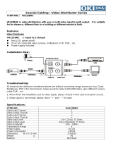
Step 1: Connecting A Camera Or Monitor
3
1
4
2
Key:
1=Camera or other video source with composite PAL or NTSC output
2=Video monitor with composite PAL or NTSC input
3=Transmitter
4=Receiver
Figure 3. Connecting A Camera Or Monitor
•To connect a camera, plug one end of a standard coaxial cable into the BNC connector on the front of
the transmitter unit and the other end into the camera. You can use any video source with a compos-
ite PAL or NTSC output.
•To connect a monitor, plug one end of a standard coaxial cable into the BNC connector on the front of
the receiver unit and the other end into the monitor. You can use any PAL or NTSC video monitor with
a composite PAL or NTSC input.
For more information about video sources and monitors, see the
Hardware Installation
section.
Step 2: Connecting Additional Items
Connect any additional items, such as alarms, audio, etc.

Pelco Manual C1977M-D (6/02) [ 13 ]
Step 3: Connecting To The LAN Port
1
2
3
1
2
3
4
Key:
1=Ethernet (10BASE-T) LAN connection to hubs, network, PCs (RJ-45 connector)
2=Ethernet Cat5 cable
3=Transmitter or receiver
Figure 4. Connecting To The LAN Port
To connect to the Ethernet network, use a standard UTP Cat5 cable with RJ-45 connectors. Plug this
cable into the RJ-45 receptacle labeled “Ethernet/UTP” at the rear of the unit. The connection to a
10BASE-T network can be made directly via a hub or switch.
Step 4: Connecting Power
Key:
1=Ethernet (10BASE-T) LAN connection to hubs, network, PCs (RJ-45 connector)
2=Ethernet Cat5 cable
3=Transmitter or receiver
4=AC plug power adapter
Figure 5. Connecting Power
Attach the power adapter. Plug the primary side into the wall outlet and the secondary side with the small
clip into the unit.
The green power LED on the front is lit constantly when the power adapter is connected correctly.
The green LINK LED next to the RJ-45 connector indicates a correct connection to the Ethernet network.

[ 14 ] Pelco Manual C1977M-D (6/02)
Step 5: Selecting An IP Address For Your Network
NOTE:
Consult your network administrator for a valid IP address.
The transmitter comes with the default address 192.168.0.1 while the receiver’s default address is
192.168.0.2. Before operating the system inside your own network, you need to set a valid IP address.
Use a terminal program attached at the RS-232 control terminal port to change the IP address.
Refer to the
Configuration Using A Terminal Program
section for a description of IP address configuration
using a terminal program.
Step 6: Using A Web Browser To Configure The Network
Configure the network using a web browser. Start your web browser and connect to the URL
http://IP-Address, where IP-Address is the IP address of the unit you want to configure. Use the
standard dot-separated format (x.x.x.x) to enter the address.
Refer to the
Configuration Using A Web Browser
section for detailed configuration instructions.
Step 7: What Next?
The system essentially is ready to use at this point. What you do now is up to you. For example, you can
connect to the web browser to watch a camera view or configure additional options (alarms, default gate-
ways, etc.) on the configuration pages.
TYPICAL APPLICATIONS
Displaying Remote Video On A Web Browser
The transmitter uses Motion-JPEG video compression or high performance H.323 coding for transmitting
across the network. This enables transmission to standard web browsers of either live video (Live Video
mode) or a stream of still images (Server Push mode).
•To activate the Live Video feature, click on Live Video above the video window on the PelcoNet
Transmission System home page (see Figure 6). The unit transmits using the H.323 coding format for
display in the browser.
To stop Live Video, click on any other option at the top of the page.
•To activate the Server Push feature, click on Server Push above the video window on the home
page. The unit continuously grabs snapshots to be JPEG encoded, transferred, and displayed con-
tinuously by the browser.
To stop Server Push, click on any other option at the top of the page.
The PelcoNet Transmission System can display live video to five users at a time. A sixth user connecting
to the same transmitter cannot receive live video.
However, Server Push can support multiple users simultaneously on the same transmitter. Image quality
is good with an update rate of one image about every 2 to 10 seconds depending on the number of users
and available bandwidth.
Browsers that do not support live video technology can display an updated still image or a stream of
images in Server Push mode.

Pelco Manual C1977M-D (6/02) [ 15 ]
Figure 6. PelcoNet Home Page

[ 16 ] Pelco Manual C1977M-D (6/02)
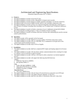
Displaying Video Via a Transmitter-To-Receiver Connection
TCP/IP
INTRANET/INTERNET
RECEIVER TRANSMITTER
MONITOR CAMERA
LAN/WAN
Figure 7. Configuration For Box-To-Box Connections
There are two ways to make a high performance multimedia transmission system for computer networks:
• One way is to use just the transmitter and connect it through the computer network to a PC with a
web browser at the receiving end.
• Another way is to connect the transmitter through the computer network to a receiver. This is often
called a box-to-box connection because it uses two PelcoNet Transmission System units.
In either case, routing dedicated cables from a camera to a monitor is not required because you can use
the existing computer network for that purpose.
The following explains a box-to-box connection.
1. First, transmitter and receiver need to be configured appropriately. If the units are supposed to be
operated in different subnets, a gateway IP address must be configured. Use the alarm IP address
field to address the destination. Enter the settings using either a terminal program or a web browser.
2. Once all addresses are configured, type c in the terminal window to establish the actual connection or pro-
gram the live video receive IP and enable the live auto connect setting through the web browser. Make sure
the alarm IP address in the unit that will initiate the connection points to the destination unit. After a few sec-
onds, video transmission begins and the camera scene appears on the monitor attached to the receiver.
Instead of using a terminal program for establishing a connection, you can attach a contact to the
alarm input. Make sure the alarm input is enabled.
You can use a web browser to connect any one of the two units, even during an active box-to-box connection.
This way you can make changes to the configuration and immediately see the result of the setting (for example,
when changing video quality). If you are connected to the transmitter, the camera picture is sent to the receiver
and web browser simultaneously. There will be a short break in the video display on the receiver monitor when-
ever the web browser requests a new frame. This is especially noticeable with the “Server Push” feature.
Full duplex audio can be transmitted in parallel with the video transmission in units that have the audio op-
tion. To do so, you need to use the web browser to enable audio on the Audio Settings Configuration Page.
Transparent data is always transmitted automatically between the two units as soon as the connection
becomes active. Data bytes entering the interface are transported to the other end transparently. There is
no flow control mechanism for the data channel. Overflowing the serial interface will cause data loss.
To sever the connection from either end, type d in the respective terminal window (or disable the alarm).

Pelco Manual C1977M-D (6/02) [ 17 ]
Diagrams of Typical Applications
Figure 8. LAN Box-To-Box Connection (Transmitter, Receiver, Fixed Camera)
Camera
Monitor
PelcoNet
Transmitter
PelcoNet
Receiver
Hub
Data
Audio
Data
Audio
Server
PelcoNet
Transmitter
PelcoNet
Receiver
Hub
Audio
Spectra II
Audio
Monitor
Keyboard
Data
Data
Video
Server
F
2
F
3
PR
ESE
T
M
A
CR
O
7
8
0
C
A
M
PV130
PV130
Figure 9. LAN Box-To-Box Connection (Transmitter, Receiver, Spectra II™)

[ 18 ] Pelco Manual C1977M-D (6/02)
Figure 10. LAN Browser-To-Box Connection (Transmitter, Browser, Fixed Camera)
PelcoNet
Transmitter
Hub
Browser
Server
Camera
PelcoNet
Transmitter
Hub
Browser
Server
Data
Spectra II
PV130
Video
Figure 11. LAN Browser-To-Box Connection (Transmitter, Browser, Spectra II)

Pelco Manual C1977M-D (6/02) [ 19 ]
Figure 12. LAN Browser-To-Box Connection (Transmitter, Browser, Spectra II, Genex
®
)
Genex
PelcoNet
Transmitter
Hub
Browser
Server
Data
Spectra II
Video
PV130
G
E
N
E
X
P
E
L
C
O
Audio
Audio
Camera
Monitor
Router
Clovis
Server
New York
Server
PelcoNet
Transmitter
PelcoNet
Receiver
Hub Hub
Router
Video Video
1or more PCs 1or more PCs
Figure 13. WAN Box-To-Box Connection (Transmitter, Receiver, Fixed Camera)

[ 20 ] Pelco Manual C1977M-D (6/02)
Figure 14. WAN Box-To-Box Connection (Transmitter, Receiver, Spectra II)
Router
Clovis
Server
New York
Server
PelcoNet
Transmitter
PelcoNet
Receiver
Hub Hub
Router
Audio
Spectra II
Audio
Monitor
Keyboard
Data
Data
PV130
PV130
1or more PCs 1or more PCs
F
2
F
3
P
RE
S
E
T
M
A
C
R
O
7
8
0
C
A
M
Video
Video
Router
Clovis
Server
New York
Server
PelcoNet
Transmitter
PelcoNet
Receiver
Hub Hub
Router
Spectra II
Monitor Keyboard
Genex
Data
Video
Data
Video
PV130
PV130
1or more PCs 1or more PCs
F
2
F
3
P
R
E
S
E
T
M
A
C
R
O
7
8
0
C
A
M
GENEX
P
E
L
C
O
Figure 15. WAN Box-To-Box Connection (Transmitter, Receiver, Spectra II, Genex)
/