W
ARNING:
B
E SURE THE ELECTRICITY TO THE WIRES YOU ARE
WORKING ON IS SHUT OFF; EITHER THE FUSE REMOVED OR THE
C
IRCUIT BREAKER OFF.
RISK OF FIRE: Exceeding maximum wattage may result in over-heating
c
onductors. Read instructions carefully. If you are unclear as to how to
proceed, consult a qualified electrician.
CAUTION: RISK OF FIRE. Use only 12V lamps with 12V systems.
Use of 12V lamps with 24V system may result in damage to the
system and surrounding area.
CAUTION: RISK OF FIRE. Must use Sea Gull No. 9488 fused plug if
used with transformers over 60w at 12 volts or 100w at 24 volts.
(USE ONLY WITH AMBIANCE 105˚ CABLE)
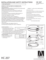
1. Secure surface mount ring to surface
by marking hole location on surface
and screw surface mount ring to
surface making sure surface mount ring does not flex out of round.
2. Drill wire exit hole in surface or run wire thru notch in surface mount ring.
3. Line up retaining springs on fixture housing with grooves in surface
mount ring and press fixture housing into surface mount ring.
1. Drill a 2 3/4” dia. hole in surface.
2. Press fixture housing into
2 3/4” dia. hole.
SURFACE MOUNTING
INSTALLATION AND SAFETY INSTRUCTIONS HC-207
FOR YOUR SAFETY
FUSED PLUG INST
ALLATION (NOT INCLUDED)
TRIM INSTALLATION
RECESS MOUNTING
*
NOT INCLUDED
*
NOT INCLUDED
*
TRIM
1/8”
HOOKS (2)
SLOTS (4)
RETAINING SPRING (2)
SURFACE
MOUNT
RING
SCREWS (2)
GROOVES (2)
HOLES (2)
NOTCH
FIXTURE
HOUSING
*
Lamp
031606
1. Cut wire to desired length.
2. Split ends of wire about (1/2”) and insert each end of the wire
as far as possible into the plug. Do not strip any insulation off
the wire.
3. Insert contact into one end of plug and press, or use pliers
until contact is flush with plug. Repeat with other contact
(see illustra
tion).
4. T
wist wires sideways, insert into notch in plug and twist back
straight.
5. Snap plug on cable.
6. Install lamp (18w max.)(not included).
1. Secure trim (not included) to fixture housing by inserting
hooks on trim into two of the four slots in fixture housing and
twist clockwise until trim snaps in place. Bend hooks up
slightly (max. 1/8”) if trim is too hard to turn and lock into
position on housing.
WARNING: Use of other manufacturers components
will void warranty, U.L. listing and create a
potential safety hazard.
2 3/4”
NOTCH
CONTACT
*FUSED
PLUG
9488
*CABLE
*TRACK
FIXTURE WIRE
U.S. PATENT #5,465,199
FIG. 1
*FUSED
PLUG
9488
*NOT INCLUDED
FIXTURE
WIRE
RISK OF FIRE: DO NOT REMOVE REFLECT
OR.
CAUTION RISK OF FIRE. 12V LAMPS MUST NOT BE USED IN
A
24V SYS
-
TEM. INSTALL CABLE SO THA
T
CAUTION PRINTED ON CABLE IS VISIBLE
AFTER
INSTALLATION AND ATT
ACH THE 24V CAUTION LABELS (SUPPLIED
WITH THE 24V TRANSFORMER) ON OR
ALONG THE TRACK EVER
Y
4 FT
.

FINAL INSTALLATION AND FUSING HC-207
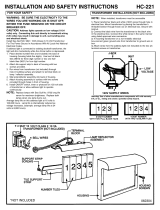
There are several ways to install the 9485
(disk-lights) using the 9774, 18w, 12V xenon lamps
(actual consumption = 16.2w):
1. When using a 60w max transformer (class II)
you are able to directly hook up three (3) 9485
to the junction box as in Figure 1.
2. For a run larger than three (3) disk-lights you
must use a class I transformer (larger than
60w). The following example demonstrates a
run of eight (8) 9485 disk-lights (8 x 16.2w
each = 130w), in this case you will need to use
a 150w transformer.
Figure 2 demonstrates fusing each individual disk
light, with a 9488 fused plug.
60W
J-BOX
9485 (3)
FIGURE 1
150W
TRACK & CABLE
9488 (8) FUSED PLUGS
9485 (8)
FIGURE 2
/


