Page is loading ...

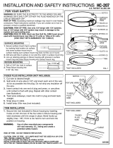
INSTALLATION AND SAFETY INSTRUCTIONS
621-CHYTEFAS RUOY ROF
Max. 200w at 12V (Indoor) 105˚C Cable
Max. 375w at 24V (Indoor) 105˚C Cable
Max. 150w at 12V (Outdoor) 60˚C Cable
Max wattage after connector on tap cable.
WARNING: BE SURE ELECTRICITY TO SYSTEM YOU ARE
WORKING ON IS TURNED OFF; EITHER THE FUSE REMOVED OR
THE CIRCUIT BREAKER SET AT OFF.
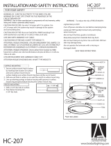
SELF TAPPING
SCREWS
CONNECTOR
COVER
FIXTURE CABLE
CENTER POST
CONTACTS
082202
NOTCH
SURFACE
MOUNTING SCREW
(NOT SUPPLIED)
TO MAKE WIRING CONNECTIONS USING 9380 CONNECTOR
A. Press 2 or 3 conductor cable into the open side of the connector
base.
B. Press 2 conductor wire from fixture into other channel of connector
base.
C. Attach connector cover with screws.
2 CONDUCTOR
CABLE FOR
INDOOR AND
2 AND 3
CONDUCTOR
CABLE FOR
OUTDOOR
CONNECTOR
BASE
FIGURE 1 VIEW UNDER SHELVING OR
FRAMELESS CABINETS
TO WIRE FOR “T” AND LEFT OR RIGHT CONNECTIONS
1. Press 2 conductor cable into the open side of connector base
opposite the notch.
2. Press another 2 conductor cable into the notch so that the end
of the cable hits the center post and the center of the cable
lines up with “V” ridge on center post.
3. Attach connector cover with screws aligning thin lip on cover
over notch.
9380
CONNECTOR
TAP CABLE
MAIN LINE
FROM
TRANSFORMER
CENTER POST
“V” RIDGE
NOTCH
TAP
PARALLEL
“T”
LEFT OR
RIGHT
WARNING: Use of other manufacturer’s components will void
warranty, safety listing and create a potential safety hazard.
CAUTION: RISK OF FIRE. USE ONLY 12V LAMPS WITH 12V
SYSTEMS. USE OF 12V LAMPS WITH 24V SYSTEM MAY RESULT
IN DAMAGE TO SYSTEM AND SURROUNDING AREA
061714
ATTENTION: RISQUE D'INCENDIE. UTILISER SEULEMENT 12V
LAMPES AVEC LES SYSTÈMES 12V. UTILISATION DE LAMPES
12V 24V SYSTEME PEUT PROVOQUER DES DOMMAGES AU
SYSTÈME ET ALENTOURS
/


