Page is loading ...

ALLEGRO
Installation &
Operating Instructions
ATTENTION : Documents to be kept by the end-user
7304
7303
7302
Allegro 26
Allegro 18
Allegro 14
421AA2212.A00 32/08

2.
1. - Specifications page 4
2. - Setting up page 4
3. - Installation page 5
4. - Electric Connection page 9
5. - Operating instructions page 12
6. - Maintenance page 17
7. - Diagnostics page 19
8. - Identification of your heater page 20
9. - Warranty information page 20
10. - How to contact CONVECTAIR page 20
TABLE OF CONTENTS
INTRODUCTION :
Dear owner,
- Congratulations on the purchase of this premium electric heater from CONVECTAIR,
manufacturer of the highest quality heating product in the electrical industry.
- To obtain the best results and the ultimate in performance and comfort, please take a
moment to read the installation and maintenance instructions shown in this manual.

3.
- QUICKSTART GUIDE -
Heat on / Heat Off key Temperature
setting keys
Mode
To turn the heater ON or OFF :
To set the temperature :
Press the key (p.12).
In Comfort mode (temperature is displayed) - press or to increase or decrease
the set point (p.13). +
Changing from °C to °F :
Turn the heater OFF. Press both and keys for 3 seconds (p.13).
Electrical requirements : 240 V
The electrical supply cable should be located 150 mm (6 in.) from the floor, centered on the
heater.
+
Installing and connecting the heater :
See diagrams on pages 6, 7, 8 and 10.
Changing mode :
Press the (Comfort > Economy > Frost protection > Program > Comfort >...
p.14-15).
Locking or unlocking the control panel :
press and together and hold for 3 seconds (p.15).
+
Diagnostics : p.19.
Contact CONVECTAIR : p.20.
Mode

4.
SETTING UP
2
IMPORTANT :
DO NOT COVER THE HEATER
Heater installation
This heater must be installed in accordance with national and local codes and CONVEC-
TAIR recommends an installation by a qualified electrician.
Covering the heater can result in severe
overheating.
The above logo warns of risk : do not
cover.
Do not cover or obstruct the air intake
or outlet on the unit as this could cause
overheating and damage the heater.
When choosing a location for this heater,
avoid drafty areas which can affect the
thermostat.
Make a note of the minimum required
clearances (height from floor, distances
from side walls or furniture, drapes, etc).
See Fig.A.
Figure A
0,15M (6 in)
0,15M (6 in)
0,10M (4 in)
1M (39 in)
SPECIFICATIONS
1
Optional accessories :
For greater comfort and energy efficiency, several
programming modules can be added to this heater
: the Pilot Wire Programmer or the wireless Power
Carrier Master and Receiver modules. For more
information, call your CONVECTAIR electrician
or dealer, or contact CONVECTAIR directly (see
contact info at the end of this booklet).
Side wire cover kits are available for situations
where connecting wires need to be hidden from view. Call your CONVECTAIR electri-
cian or dealer, and be sure to specify the model number.

3
5.
INSTALLATION
3- Use the mounting bracket as a template by holding
it against the wall, flush to the floor. Use the «B» marks
to locate the bottom fasteners (Fig. D). This will place
the heater at 4’’ off the floor.
Locking tab
Figure B
5 - Fasten the bracket according to the Type A or B diagrams (page 6), using 4 screws
for the bracket and 2 screws for the GoBox, tightening the screws in the order shown
on page 6.
4- Raise the bracket into position lining up the bottom
holes with the wall marks. Check that the bracket is
level and that it is right side up (Fig. E – F – G).
2- Unclip the cover of the plastic connection box
(Fig. C).
1- Remove the bracket from the heater by pressing and
pulling both locking clips (Fig. B).
Figure C
GoBox
7 1/8"
180 mm
Figure D
7’’
170
PEN
BRACKET
B
MARK
B
MARK
USING THE MOUNTING BRACKET
AS A TEMPLATE FOR MARKING.
Plan ahead :
- Determine the heater location, taking into account the required clearances (Fig.A.).
- Ensure that the electrical wiring is accessible near the heater connection box : 6 in.
(15 cm) off the floor, centered on the heater (see page 6 – Type A), and that a sufficient
length is available for the connection.
- If a wall junction box is required, position this box horizontally, with the bottom edge of
the box at 6 in.(15 cm) above the floor positioned as shown on page 6 – Type B.

6.
Electric cable
location
150mm
6’’
Outside
dimension
WItHout A WAll juNctIoN box A
TYPE
Note : the position of the single gang
wall junction box depends on each
model (see Fig. E – F – G).
150mm
6’’
Electric cable
location
Outside
dimensions
12
3
4
56
Tighten screws in the order
shown here
12
3
4
56
Tighten screws in the order
shown here
WItH A WAll juNctIoN box b
TYPE
For installation
over a wall junction
box, remove the
knock-out panels as
shown.

7.
Encombrement
de l’appareil
Autres
Puissances
Version
500 à 1000W
100
min
220 468
170
100
min
468
680
Entraxe A
Entraxe
227
Largeur Appareil
(mm)
Encombrement
de l’appareil
Figure E
7304 - Allegro 26
170
470
220
150
Entraxe
256
Longueur Appareil
227
Encombrement
de l’appareil
Autres Puissances
Figure F
(mm)
220mm
150mm
226mm
A
150mm
220mm
468mm
Entraxe
Longueur Appareil
680mm
Entraxe
468mm
Version 500 à 1000W
Autres Puissances
Modele Haut 7304
Encombrement de l'appareil
Encombrement de l'appareil
470
7303 - Allegro 18
170
Encombrement
de l’appareil
500 => 1000W 1250 => 2000W
Overall
dimension
Overall
dimension
Distance
Bracket
Width
Overall
dimension
1250 => 2000W
Bracket
Width
min
Bracket
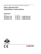
7304 - ALLEGRO 26 - Figure E
Power (W) 500 750 1000 1250 1500 1750 2000
Bracket 137mm 5,4’’ 178mm 7’’ 178mm 7’’ 140mm 5,5’’ 178mm 7’’ 248mm 9,8’’ 320mm 12,6’’
Width 329mm 13’’ 369mm 13’’ 409mm 16,1’’ 489mm 19,3’’ 569mm 22,5’’ 649mm 25,6’’ 769mm 30,3’’
A115mm 4,5’’ 115mm 4,5’’ 135mm 5,3’’ 227mm 9’’ 227mm 9’’ 227mm 9’’ 227mm 9’’
Height 680mm 26,8’’ 680mm 26,8’’ 680mm 26,8’’ 680mm 26,8’’ 680mm 26,8’’ 680mm 26,8’’ 680mm 26,8’’
18,5’’
26,8’’
6,7’’
18,5’’
6,7’’
100
3,9’’
100
3,9’’
9’’
7303 - ALLEGRO 18 - Figure F
Puis. (W) 500 750 1000 1250 1500 1750 2000
Bracket 178mm 7’’ 178mm 7’’ 248mm 9,8’’ 320mm 12,6’’ 405mm 16’’ 405mm 16’’ 405mm 16’’
Width 489mm 19,3’’ 489mm 19,3’’ 569mm 22,5’’ 649mm 25,6’’ 769mm 30,3’’ 849mm 33,5’’ 849mm 33,5’’
Height 470mm 18,5’’ 470mm 18,5’’ 470mm 18,5’’ 470mm 18,5’’ 470mm 18,5’’ 470mm 18,5’’ 470mm 18,5’’
18,5’’
10,1’’
6,7’’
100
3,9’’
9’’

8.
Encombrement
de l’appareil
170
100
min
360
Entraxe
227
Largeur Appareil
(mm)
148
Figure G
7302 - Allegro 14
Overall
Dimensions
Width
Bracket
7302 - ALLEGRO 14 - Figure G
Power (W) 500 750 1000 1250 1500 1750 2000
Bracket 140mm 5,5’’ 178mm 7’’ 248mm 9,8’’ 405mm 16’’ 405mm 16’’ 535mm 21,1’’ 535mm 21,1’’
Width 489mm 19,3’’ 569mm 22,5’’ 649mm 25,6’’ 849mm 33,5’’ 849mm 33,5’’ 1129mm 44,5’’ 1129mm 44,5’’
A227mm 9’’ 227mm 9’’ 227mm 9’’ 222mm 8,7’’ 222mm 8,7’’ 297mm 11,7’’ 297mm 11,7’’
Height 360mm 14,2’’ 360mm 14,2’’ 360mm 14,2’’ 360mm 14,2’’ 360mm 14,2’’ 360mm 14,2’’ 360mm 14,2’’
6,7’’ 5,8’’
14,2’’
100
3,9’’
A

9.
ELECTRIC CONNECTION
4
CONVECTAIR recommends that this heater be installed in accordance with
national and local codes.
To prevent short circuits and electrical shocks turn the power off at the main
panel before attempting the installation or any repairs.
If the power cable is damaged it must be replaced by the manufacturer, an
approved service depot or a technician with similar qualifications.
Be aware : Wiring color coding.
When connecting the heater’s connection box to the house wiring, main-
tain the same color code for all heaters.
L1 = Power, Line 1 – red (in the US : white)
= Ground ( ) - copper wire
L2 = Power, Line 2 – black
PW = PILOT WIRE
See Fig. K and L
The Pilot Wire (PW) must never be connected to the ground.
CAUTION :
This heater must be connected to a 240 Volt or 208 Volt (60 cycles) circuit. Dis-
connect the power supply before making wiring connections to prevent electrical
shock and equipment damage. If you are using a Programmer system, make sure
to cut the power off ALL electrical heating circuits in the home (for more informa-
tion, see the CONVECTAIR model 7392 installation notice).

10.
To install the Pilot Wire (PW),
do not forget to detach the ton-
gue on the bottom side of the
GoBox (as above).
!
Fig. K
WItHout
wall junction
box A
TYPE
Fig. L
uSINg a wall
junction box
b
TYPE
- Connect the supply wire coming from the wall into the connection block inside the
GoBox in the right sequence (see «Wiring Color coding, page 9).
CONNECTING THE HEATER
CAUTION BEFORE CONNECTION
!
NON
OUI
Wrong Right

11.
CANADA
WItHout using a pilot wire (PW).
B - Black R - Red W - White C - Copper PW - pilote wire
WItH the use of a pilot wire (PW).
GoBox
POWER LINE
PW R
BC
PW L2 L1
GoBox
POWER LINE
PW W
BC
PW L2 L1
GoBox
POWER LINE
PW R
BC
PW L2 L1
GoBox
POWER LINE
PW W
BC
PW L2 L1
- Place the cover on the GoBox, clipping each corner into position, and lock it with the
supplied screw.
- Insert the heater plug (Fig J, rep 2) into the GoBox receptacle (Fig. J, rep 1) until it is
locked in place.
- Holding the heater at an angle towards you, hook the lower bracket tabs into the
heater.
- Push the heater towards the wall until it clicks into the upper locking tabs (Do not
pinch the connecting cord).
MOUNTING THE HEATER.
Figure J
Rep.1
Rep.2
U.S.A. CANADA U.S.A.

12.
OPERATING INSTRUCTIONS
5
Mode
Operation
During the heating season, the CONVECTAIR heater will remain warm and the ambient
temperature will remain constant. It is normal in very cold temperatures for the unit to
become hot. Caution is advised when young children are present.
THE BUILT-IN THERMOSTAT OFFERS 5 MODES :
Heat On / Heat Off key Temperature and operating mode LCD display
Temperature setting keys
Operating mode selection key
Heating indicator symbol
OFF :
Comfort:
Economy setback:
Frost protection :
Program :
no heating.
the heater maintains the set temperature
the temperature is lowered to the desired setting wi-
thout changing the comfort setting (night setback,
unused rooms, temporary absence).
the temperature is set at 45°F(7°C) for long term
absence.
the heater can respond to signals from a Program-
mer (CONVECTAIR 7392, sold separately).
[no display]
°C/°F
ECo
Hg
P

13.
Turning the heater ON.
Rep.1
Mode
Note : When the heater is first connected, it will
be in the OFF position, with a blank display. To
start, press briefly on the Heating ON/OFF key
(rep 1) and the display shows the default comfort
set point : 19.0°C (66°F).
The setpoint display is set to °C by default.
In order to display °F : press the ON/OFF key to turn the heater OFF. Then, press the
ON/OFF and + keys at the same time and hold for about 3 seconds. The display will
show °F.
Repeat this operation to go back to °C.
To shut off the heating function, press briefly on
the Heating ON/OFF key (Rep.1). The display
goes blank.
Note : the heater still retains all settings in memory.
It remains in standby mode.
Shutting off heater operation.
Rep.1
Mode
Setting the desired temperature.
Turn the heating on. The display shows 19.0°C (or
66.0°F if set in Fahrenheit). Using the + and – keys,
you can raise or lower the setting as you wish by
0.5° each time the key is pressed.
This is how you can adjust the thermostat to your
desired temperature (see example).
To confirm this comfort level, you may follow the
following procedure, preferably in the evening (no
sun influence) : close the doors to the room where
the heater is located ; wait about one hour to allow
for the temperature to stabilize, then adjust the set-
ting up or down (+ or – keys) until the temperature
feels right. Allow another hour to verify that the
temperature has stabilized at the correct level.
Mode
Mode
Selection °C or °F display.

14.
Comfort mode (.19.0°C - 66.0°F,...).
When the thermostat is in Comfort mode, the
heater will maintain the set temperature (19.0°C
66.0°F) without responding to any Programmer
instruction.
To change the set temperature, simply press the +
or – keys to change the setting in steps of 0.5°.
Mode
Exception to the Comfort mode :
If the heater is connected to a Programming system, it will still respond to a Frost Protec-
tion instruction.
To select the Comfort Mode :
Press the Mode key several times until the set temperature value appears on the dis-
play (19.0°C. 66.0°F,...).
Eco mode.
Mode
Mode
When the heater is in ECo Mode, it will maintain
the temperature at a lower value. This setting is
useful to reduce energy consumption at night or
when a room is temporarily unused.
To select the ECo mode :
Press the Mode key briefly until the word ECo ap-
pears on the display.
To display the ECo temperature setting :
While in ECo mode, press the + or – key. The ECo
temperature setting will appear on the display (the
default setting is 3.5°C or 7°F below the Comfort
temperature).

15.
To change the ECo temperature :
When the display is in Eco mode, you have the option of choosing a set temperature.
The Eco temperature can be set at any value between the Frost Protection temperature
(7°C or 45°F) and the Comfort temperature minus 0.5°.
Select the ECo mode. Press and maintain the Mode key until the temperature value
starts to blink. Release the Mode key and adjust the temperature up or down in 0.5°
steps using the + or – keys. Press Mode to confirm the setting.
Note : the ECo temperature is relative to the Comfort temperature. If the Comfort
setting is changed, the ECo temperature will change automatically to maintain the same
difference between the two values.
Exceptions to the Eco Mode :
if the heater is connected to a Programming system, it will still respond to a Frost Pro-
tection instruction.
Frost Protection setting : HG
In case of longer term absence (24hrs or more), the
HG mode will maintain the room temperature at 7°C
(45°F). You can reduce your energy consumption
while maintaining a minimum safe temperature.
To select the HG mode :
Press the Mode key until the display shows : HG.
Mode
Locking the heater controls
Mode
Mode
Mode
The control pad can be locked from any Mode
selection to prevent tampering.
To lock the control : From any Mode setting, press
both the + and the – key at the same time and hold
for about 3 seconds. The display will blink to show
that the keyboard is locked.
Pressing any key when the keyboard is locked will
cause the screen to display «FF» and the heater will
not respond.
To unlock the keyboard, repeat the same procedu-
re : press and hold both + and – keys at the same
time for about 3 seconds.

16.
Program Mode : P
This mode allows the heater to respond to instruc-
tions from a central Programmer system or from
an individual Programmer module. The thermostat
display will show what instruction is being received
(see summary table below).
To select the Program Mode :
Press the Mode key briefly until the display shows the temperature setting with the letter
P on the top right of the screen (19.0P or 66.0P, for instance).
The temperature is equal to the Comfort setting. To modify the set temperature, simply
press the + or – keys.
Suggestion :
For better comfort, we recommend that you keep this heater in the Programming
Mode.
This function allows your heater to react automatically to instructions sent by a central
Programmer System or by an individual Programmer cassette inserted in the receptacle
located next to the thermostat.
Mode
PROGRAMMER
INSTRUCTION
HEATER DISPLAY RESULTING MODE
Setback on. ECOPTemperature is lowered by 3.5°C (7°F) from
the comfort setting (or as selected).
Frost Protection on. HGPMaintains the room temperature at 7°C
(45°F).
SUMMARY TABLE OF PROGRAMMING MODES SENT BY A PROGRAMMER :
Note :
Frost Protection instructions from a Programming system will override all other settings
even if a heater is not set in the Program Mode.
In that case, the heater screen will display the appropriate symbol (see table above) but
the letter «P» will be flashing.

17.
MAINTENANCE
6
To keep your CONVECTAIR unit clean, regu-
lar maintenance is suggested. To remove dust,
use a soft cloth. To remove a stain, use a damp
cloth. For a better performance and a maximum
efficiency, it is suggested that dust and lint be re-
gularly removed from the protective grille situated
at the base of your CONVECTAIR heater.
NEVER USE ABRASIVE OR ACETONE-BASED PRODUCTS TO CLEAN THE HEA-
TER AS THIS MAY CAUSE DETERIORATION OF THE EPOXY FINISH.
ANY REPAIR ON YOUR CONVECTAIR HEATER SHOULD ONLY BE DONE BY A
QUALIFIED TECHNICIAN AFTER DISCONNECTING THE HEATER.
Operation and Maintenance TIPS
Your CONVECTAIR heater will become hot when in use. Caution is advised when
young children are present.
Do not insert small objects through the front louvers : this could cause electrical short-
circuit, fire or damage to the inner components.
Any use or modifications not approved by CONVECTAIR may cause electrical short-
circuits, fire or injuries to the users.
In certain cases, it is possible for yellowing of the grille to occur over time. This is
not due to a manufacturing defect. This is caused by surrounding air, which contains
smoke or dust, being heated and released through the grille.
Prevention : it is suggested that grilles be frequently cleaned especially
with units installed in locations where cigarette smoke is present or in the
kitchen. Never use this heater during construction work or other activities
that generate a lot of dust.
Note : The first time your CONVECTAIR heats, a light smoke could be
released. This is normal and should disappear after about 2 to 3 minutes.
Rep. 1
Figure M
Temperature limiting control :
This heater is equipped with a manual reset control.
In case of a malfunction of the unit (blocked air output
or intake, for example) the heater will stop heating
automatically. After correcting the malfunction the
heater can be reset. To restart the heater, push the
button on the upper back panel of the heater.

18.
You will need : a small flat-head screwdriver.
1 – Shut the power to the heater.
2 – Remove the heater from the wall bracket by
firmly pressing both locking clips then pulling
the heater towards you (page 5, Fig. B).
3 – Place the heater on the floor and locate the
plug connecting the unit electrical cord to the
GoBox on the wall-bracket.
4 – Lightly pull the plug away from the wall to
locate the locking tab (at the base of the plug,
against the wall).
5 - Insert the screwdriver into the rightmost hole
in the plug and press it against the locking tab
(Fig. P)
6 - Pull the plug upwards
To remove a heater (house cleaning or painting, for instance) :
CAUTION :
Do not allow dust, particles, paint or other liquids to fall into the GoBox
receptacle.
!
To put the heater back :
1 - Plug the heater cord back into the GoBox receptacle (Fig.P).
2 - Press the plug firmly into position, to lock it.
3 - Mount the heater on the wall bracket (Caution : do not pinch the heater cord).
GoBox
Figure P
Rep.1

DIAGNOSTICS
7
PROBLEM VERIFICATION ACTION
No Heat
The display screen is blank Put the heater ON (top left key on the
control ON/OFF.
The screen remains blank. Check the breakers for the heating
circuits.
The display screen is on, the
heating indicator is not visible :
Check the set temperature : the ambient
temperature does not require any heat.
The display screen is on, the
heating indicator is still not visi-
ble. The heater may have been
shut by the Temperature Limiting
Control :
Clean the inlet and outlet grilles and reset
the overheat protection (see the Tempera-
ture Limiting Control section).
The heater in ECo or HG mode,
or in EcoP, OFFP or HGP mode :
Check that the heater is in comfort mode
or that it has not been cut by the central
Programming system.
The heater does not
stop heating
Has the temperature setting been
changed ?
Is the heater affected by a draft, a
nearby unheated space, an open
window or an open door ?
Reset the temperature level.
Correct the source of cold affecting the
heater.
Programming seems
out of order
Are the Programmer (and the re-
ceiver module, if any) operating ?
Check the Programmer (and receiver
if any) – for more details, refer to their
instruction manuals.
Make sure that the heater is in Program
Mode.
Remove and reinsert the Programmer (and
receiver if any) in its receptacle.
IN ALL OTHER CASES, CONTACT YOUR ELECTRICIAN
OR THE NEAREST CONVECTAIR REPAIR CENTER.
19.

20.
GUARANTEE
9
30, Carré Sicard, Sainte-Thérèse (Québec), CANADA J7E 3X6
Phone : (450) 433-5701 Fax : (450) 434-3166
Email : support@convectair.ca
www.convectair.com
2 years against all defects
5 years on heating element
All CONVECTAIR units are subject to a double warranty: 2 years on all parts and
manufacturing defects and 5 years on the heating element itself.
Warranty is applicable from date of purchase by the customer and under certain specific
conditions. All details furnished with each unit. Please keep your invoice (purchase and/
or installation).
REPAIR CENTERS :
Contact CONVECTAIR for information regarding your closest repair center.
Toll-free : 1-800-463-6478
IDENTIFICATION OF YOUR HEATER
8
IMPORTANT : Product information appears on
the heater’s identification label.
The identification label is located on the lower
right hand side of the heater (same side as the
thermostat). It includes :
– The complete model number and it produc-
tion reference number (rep. A) that must be
included in any warranty claim.
– Its capacity in watts (rep.B).
– Its approval standard (rep. E,C,D,F).
CONSTRUCTEUR N°179
TYPE
W
MADE IN FRANCE
N° 04.08
Rep. D
Rep. B
Rep. E1 Rep. F1/F5
Rep. C
Rep. A
Rep. X
/