Page is loading ...

936.2519/C/0706/1.2e
ZAS 40
20410011
ZAS 41
20410012
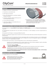
Rafter fasteners
Rafter brackets
ZAS 40
ZAS 41
20410011
20410012
Q
To mount parabolic antennas on rooftops
Q
TÜV certifi ed for parabolic antennas with a diameter of up to 1 m
Q
ZAS 40 for one parabolic antenna
ZAS 41 for one parabolic antenna and an additional VHF antenna
Q
Mounting directly from the outside or through the battens onto
the rafter
Q
Flexible adaptation to the gaps between the rafters with
telescopic pipe
Q
Continuously adjustable for any roof slope
(limited only with cover plate)
Q
Cable is inserted through mast tip with ZTC 08
(included in delivery scope of ZTS 41)
Q
With earth screw, mast cap and 6 fi xing screws 10 x 100 mm
Q
Hot-dip galvanised
Type
ZAS 40 ZAS 41
Order no.
20410011 20410012
Mast diameter (Ø)
mm 48 48
Mast length (L)
mm 900 1,300
Gaps between rafters (B)
mm 510-900
Roof slope
° 0-90
Frame dimensions approx.
mm 580 to 980 x 148 x 40
Suitable for parabolic antennas
CAS 60/CAS 75/CAS 90
Appropriate mounting accessories
ZTS 40 rafter bracket mounting set
Allowable bending moment
1)
Nm 700
Packing unit/weight
pc./kg 1/6.5 1/7.5
¹
)
The wind load of the masts has already been considered (applies to 800 N/m² and 1,100 N/m²)
Rafter bracket mounting set
ZTS 40
20410013
Q
For securing ZAS 40 and ZAS 41 rafter brackets
Q
The set comprises:
- Lead cover plate (410 x 410 mm)
- Mast cap for insertion of eight or ten cables
- Cover collar (Ø: 48 mm)
- 6 securing bolts(10 x 100 mm)
Type ZTS 40
Order no. 20410013
Suitable for ZAS 40, ZAS 41 rafter brackets
Packing unit/weight pc./kg 1/2.9

Q
Remove a suffi cient number of roof tiles
Q
Extend the rafter bracket to the pitch of the rafters or the counterlaths
Note:
Align the rafter bracket and the lead cover to suit the covering materials
of the roof. Take care to leave enough overhang above and below the
gap in the roofi ng material.
The cross-tube of the ZAS 40 and ZAS 41 rafter brackets has an offset
of about 2 cm relative to the side securing clips. Depending on the
alignment, this offset allows the rafter bracket to be moved upwards or
downwards within the roof space and for instance in conjunction with
the rafter bracket mounting set ZTS 40 to achieve an optimum position
relative to the existing roof tiles.
When the installation is made on steeper roofs, the shorter securing
section should point downwards relative to the slope of the roof
Q
Mark out the six screw holes on the rafters or counterlaths, and drill pilot holes using a 6.5 mm Ø drill (50 mm deep)
Q
Screw the rafter bracket into place using the six securing bolts supplied with the mounting set (10 x 100 mm) on the
counterlaths or the rafters, using a 17 mm spanner (if the counterlaths are too thin, place packing underneath the rafter
bracket in the areas of the bolts)
Q
Tighten the telescopic tube securing screw
Q
Lead the earthing wire (16 mm
2
copper or 25 mm
2
aluminium) into the earthing terminal and tighten the nut
Q
Slide the mast along the telescopic tube, so that the lead cover matches the joints of the roof tiles
Q
If you intend to lead cables through the mast tip, remove the mast cap that is fi tted
Q
Swing the mast towards the gable and pull the lead cover and the cover collar over the mast tip
Q
Put on the inner part of the mast cap ZTC 08 with the cap open
Q
Swing the mast further down and insert the required number of cables into the opening at the bottom of the mast. Push the
cables towards the tip of the mast, until they project a suffi cient distance
Q
Push the cables into the cable grip at the top edge of the mast cap and close the cap
Q
Using a spirit level, align the antenna mast vertically, and tighten the four nuts (M10) using a 17-mm spanner
Q
Then push the lead cover down into position and fold the upper edge and side edges of the plate up by about 2 cm, to direct
any precipitation that penetrates securely on the cover below
Q
Tighten the cover collar over the entry spigot of the lead cover
Q
After laying the cable as required, replace the roof tiles
Installation steps
Safety Instructions:
1.
During installation, take care that the roof framing has suffi cient load-bearing capacity
2.
Parabolic antennas (max. Ø: 100 cm) may be erected only up to the maximum mast height (about 800 mm)
3. For a mast length of 1,300 mm (ZAS 41) the refl ector must be installed below and the FM antenna above
936.2519/C/0706/2.2e/ZWT Technical data subject to change.
Internet: www.kathrein.de
KATHREIN-Werke KG • Phone +49 8031 184-0 • Fax +49 8031 184-306 • Anton-Kathrein-Straße 1 - 3 • P.O. Box 100 444 • 83004 Rosenheim GERMANY
/