Page is loading ...

Envelope Imager CS
OPERATIONS
MANUAL
Revised: 9-13-07
Part #: M-3418
RENA SYSTEMS INC.
136 Green Tree Road STE 140
Oaks, PA 19456-1069
Phone: (610) 650-9170
Fax: (610) 650-9171
E-Mail: support@renausa.com
Web Site: www.renausa.com

SAFETY PRECAUTIONS
THIS EQUIPMENT PRESENTS NO PROBLEM WHEN USED PROPERLY.
HOWEVER, CERTAIN SAFETY RULES SHOULD BE OBSERVED WHEN
OPERATING THE ENVELOPE IMAGER CS PRINTER.
BEFORE USING THE PRINTER, YOU SHOULD READ THIS MANUAL
CAREFULLY AND FOLLOW THE RECOMMENDED PROCEDURES, SAFETY
WARNINGS, AND INSTRUCTIONS:
9 Keep hands, hair, and clothing clear of rollers and other moving parts.
9 Avoid touching moving parts or materials while the machine is in use. Before clearing a jam, be sure
machine mechanisms come to a stop.
9 Always turn off the machine before making adjustments, cleaning the machine, or performing any
maintenance covered in this manual.
9 The power cord and power supply supplied with the machine should be plugged it into a properly
grounded wall outlet located near the machine and easily accessible. Failure to properly ground the
machine can result in sever personal injury and/or fire.
9 The power cord and wall plug is the primary means of disconnecting the machine for the power
supply.
9 DO NOT use an adapter plug on the line cord or wall outlet.
9 DO NOT remove the ground pin from the line cord.
9 DO NOT route the power cord over sharp edges or trapped between furniture.
9 Avoid using wall outlets that are controlled by wall switches, or shared with other equipment.
9 Make sure there is no strain on the power cord caused by jamming between the equipment, walls or
furniture.
9 DO NOT remove covers. Covers enclose hazardous parts that should only be accessed by a qualified
service representative. Report any damage of covers to your service representative.
9 This machine requires periodic maintenance. Contact your authorized service representative for
required service schedules.
9 To prevent overheating, do not cover the vent openings.
9 Use this equipment only for its intended purpose.
In addition, follow any specific occupational safety and health standards for your workplace or area.
This manual is intended solely for the use and information of Rena Systems Inc., its designated
agents, customers, and their employees. The information in this guide was obtained from several
different sources that are deemed reliable by all industry standards. To the best of our
knowledge, that information is accurate in all respects. However, neither Rena Systems Inc. nor
any of its agents or employees shall be responsible for any inaccuracies contained herein.
The Envelope Imaging Company
TM
is a registered trademark of Rena Systems Inc.
Hewlett-Packard is a registered trademark of Hewlett-Packard Corporation.
Windows 98, 2000, NT and XP are registered trademarks of Microsoft Corporation.
IBM is a registered trademark of International Business Machines.
All other trademarks are the property of their respective holders.
All rights reserved. No part of this book may be reproduced or transmitted in any form or by any means, electronic or mechanical,
including photocopying, recording, or any information storage and retrieval system, without permission in writing from the publisher

TABLE OF CONTENTS
i
Table of Contents
Section 1 – Getting Acquainted 1
Front View
Rear View
1
2
Section 2 – Installing the Printer 3
Choosing a Location
Unpacking and Setup
Connecting the Envelope Imager CS
Connecting to the Computer
Installing the Inkjet Cartridges
Setting up the Feed
Installing the Printer Driver
3
3
5
5
6
7
9
Section 3 – Operating the Envelope Imager CS 14
Setting Up a Job in MS Word
Printer Driver Properties
Paper/Quality Tab
Finishing Tab
Effects Tab
Basics Tab
Color Tab
14
17
17
19
19
19
20
Section 4 – Maintenance 21
The Inkjet Cartridge
Jams in the Printer
Replacing the Sheet Separators
Cleaning
21
22
23
23
Section 5 –Trouble Shooting 25
HP Inkjet Print Cartridges
The Printer
25
26
Appendices 27
Appendix A – Specifications
Appendix B – Supplies and Optional Hardware
27
28
Index 29

TABLE OF CONTENTS
ii
NOTES
______________________________________________________
______________________________________________________
______________________________________________________
______________________________________________________
______________________________________________________
______________________________________________________
______________________________________________________
______________________________________________________
______________________________________________________
______________________________________________________
______________________________________________________
______________________________________________________
______________________________________________________
______________________________________________________

SECTION 1
GETTING ACQUAINTED
1
Section 1 – Getting Acquainted
Front View
1.
Paper Key –The LED on this key blinks when an action is required, such as loading
paper or a misfeed (paper didn’t feed into position, or jammed). Once the problem is
solved (paper loaded, jam cleared), press this key to continue printing.
2.
Cancel Key – Pressing this key will cancel/clear the job being printed.
Tip: Cancel the job from your software and clear (cancel) all pending documents from
the Envelope Imager CS printer driver queue; then press this key.
3.
Adjustable Side Guide – Holds the paper against the fixed side guide.
4.
Fixed Side Guide – The paper is registered against this guide.
5.
Soft Power Button – Pressing this button will toggle the printer from ready mode to
standby mode. Standby mode parks the ink cartridges and reinitializes the printer. USB
users will get an audible tone from their computer acknowledging USB disconnect and
reconnect. The fan will continue to run when the printer is in standby mode. The printer
will automatically exit the standby mode if data is sent to it.
Button Light
Description
On Steady Printer is Ready.
Blinking Printer is receiving/processing data.
Off Printer is in standby mode or powered off (main power off).
2
1
5
4
3

SECTION 1
GETTING ACQUAINTED
2
Rear View
1.
Parallel Port Connection – The Centronics Parallel cable attaches here.
2.
USB Port Connection – The USB cable attaches to the printer here.
3.
Main Power Switch – This switch connects/disconnects main power to the printer.
Note: The printer performs an extensive cartridge cleaning process when first powered
on and a print job is sent. It is recommended that you leave the printer’s Main Power
Switch on, unless you plan not to use the printer for an extended period of time.
4.
Power Connection – The printer’s power pack is connected here.
Use only the power pack that was included with the printer.
5.
Clear Paper Button – Operates the paper transport motor to help clear any paper in the
transport system. The feed rollers are not engaged during this process.
6.
Rear Paper Support – Provides the proper angle to enhance paper feeding and
separation.
7.
Adjustable Side Guide – Holds the paper against the fixed side guide.
8.
Rear Paper Guide – Allows for adjustments in stack angle, based on paper type and
length. Helps to force the paper against the separation area.
9.
Fixed Side Guide – The paper is registered against this guide.

SECTION 2
INSTALLING THE PRINTER
3
Section 2 – Installing the Printer
Before using the Envelope Imager CS printer the following must be done:
• Choose a location for the printer
• Unpack and assemble the printer.
• Install the Inkjet Cartridges
• Set up the feed on the printer
• Plug in the printer and connect it to the computer
• Install the Printer Driver.
Choosing a Location
The Envelope Imager CS should be placed on a sturdy worktable or cabinet at least 9
inches from any walls. Protect the Envelope Imager CS from excessive heat, dust,
and moisture – avoid placing it in direct sunlight.
Unpacking and Setup
Remove the Printer and its parts from the carton. Save the packing material. Remove
all packing tape. The screws that attach the various parts of the guides to the printer
are under the tape in their respective positions.
Begin by installing the Fixed Side Guide. It is
held in place by two screws [1]:

SECTION 2
INSTALLING THE PRINTER
4
Next install the Adjustable Side guide using
the two screws [2] provided.
Attach the Rear Paper Support using the two
knobs [3] provided.
NOTE: the large slots fit over the socket
head screws.
Install the Rear Paper Guide using the
thumbscrew and washer [4] provided. The
washer goes between the screw and the Rear
Paper Support.

SECTION 2
INSTALLING THE PRINTER
5
Connecting the Envelope Imager CS
Plugging in the Printer
1. Make sure that the Main Power Switch [3], is in the OFF position.
2. Connect the power cord from the power pack to the connector [4] at the rear of
the Printer.
3. Plug the power cord into the power pack and then plug the other end into a 115-
220 Volt AC, 50/60 Hz. Grounded outlet. A surge protector is recommended.
4. The Main Power Switch [3] can be turned on after you attach the power cord to
the Power Receptacle [4]
CAUTION
USE THE POWER SUPPLY PACKED WITH THE PRINTER.
DO NOT USE AN ADAPTER PLUG OR EXTENSION CORD TO
CONNECT THE PRINTER TO THE WALL RECEPTACLE.
DO NOT USE OUTLETS CONTROLLED BY WALL SWITCHES.
DO NOT USE AN OUTLET THAT SHARES THE SAME CIRCUIT WITH
LARGE ELECTRICAL MACHINES OR APPLIANCES.
Connecting to the Computer
Important: Before connecting the printer to
the computer, for the first time; please be
sure to follow the instructions for “Installing
the Printer Drivers”.
Power the printer off before
connecting/disconnecting the Parallel cable.
The Printer has both a USB [2] and a Parallel
Port [1] connection. The two ports are
located one above the other as shown.
USB Users: Plug the USB cable from your
computer, into the printer’s USB Port.
Parallel Users: Plug the parallel printer cable
from your computer into the printer’s Parallel
Port and latch the two locking clips.

SECTION 2
INSTALLING THE PRINTER
6
Install the Inkjet Cartridges
The Envelope Imager CS uses two ink cartridges, the C6657 Color cartridge and the
C6656 or HP58 Black cartridge. Use the C6656 Black cartridge for everyday printing
and the HP58 Black Cartridge for photos and high quality printing.
Install and replacing the cartridge is done in the following manner:
1. Plug in the Printer and turn the
main power switch ON. Open the
top cover and press the soft power
button [1], the button will light...
The printhead carriage will move
side to side and the printhead
wiper mechanism will move to its
downward position. Wait until
the mechanism stops moving.
Then open the two printhead
latching covers [2] by lifting them
from the front.
2. Inset the cartridge into their
appropriate positions as shown.
The color cartridge goes on the
left.
3. Press down on the cartridge
latches until you hear a click, and
then close the top cover.

SECTION 2
INSTALLING THE PRINTER
7
Setting up the Feed
They printer’s feed systems is adjusted as follows:
1. Move the adjustable side guide so that the locking screws on the sheet separator
assembly are accessible.
2. Loosen the locking screw and raise the separator, then tighten the locking screw to
hold the separator in the up position. Repeat this step for all separators.
3. Place a single piece of media
under the separators and against
the fixed side guide.
On the separators that have media
beneath them; loosen the separator
locking screws, and let the
separators drop onto the media.
Then tighten the locking screws.
4. Position the adjustable side guide
so that it about 1/32-inch from the
sides of the media. Tighten the
locking screw on the side guide.
5. If not already present place a
single piece of media into the feed
area so it is starting to feed under
the separators. Then place
additional media into the feed area;
making sure the media stack is
fanned so the bottom piece is
closest to the separation point.
IMPORTANT
Be sure that unused separators are
locked in their raised position. If not,
they will rub on the feed rollers,
causing transport problems and
damage to the rollers and separators.

SECTION 2
INSTALLING THE PRINTER
8
½”
6. The rear paper support is adjustable
by loosening the two locking knobs
and raising it up or down.
Start with the rear paper support in
the center position (knobs aligned
with small reference holes).
If you experience feeding problems;
raise or lower the rear paper
support, to obtain the best angle of
contact between the media and the
feed rollers/separators.
7. Adjust the rear paper guide by
loosening the locking screw and
position the guide so that the back
edge of the media is raised
approximately 1/2-inch above the
rear paper support.
8. The same procedure is used for
other media sizes and types.
NOTE: The amount of media that can be stacked on the printer is determined by the
weight of the material. The feeder may not feed larger and heavier media when the
stack is full. If this is the case reduce the amount of media in the stack until the feeder
functions properly.

SECTION 2
INSTALLING THE PRINTER
9
Installing the Printer Driver
Please be sure to follow the procedure as described below.
1. Place the “Driver CD”, supplied with the printer, into your CD-ROM drive.
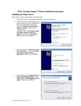
2. Connect the printer to the computer via the
port you wish to use (USB or Parallel) and
then turn the printer ON. After a little
while, the “Welcome to the Found New
Hardware wizard” will open on the
computer screen.
If prompted with “Can Windows connect
to Windows Update to search for
software?” Click on the “No, not this
time” and then click on NEXT>.
3. When prompted with “What do you want
the wizard to do?”, Click on the “Install
from a list or specific location
(Advanced)” and then click on NEXT>.
4. When prompted with “Please choose your
search and installation options.”, select
“Don’t search. I will choose the driver to
install.”. Then Click on NEXT>.

SECTION 2
INSTALLING THE PRINTER
10
5. When prompted to “Select a hardware
type, and click Next.”, scroll down the
list and select “Printers”. Then Click on
NEXT>.
6. When the “Add Printer Wizard”
window appears; Click on the “Have
Disk…” button.
7. When the “Install From Disk” window
opens; Click on the “Browse…” button.

SECTION 2
INSTALLING THE PRINTER
11
8. Locate the “Printer Drivers” folder on
the “CS Driver CD”, which you
previously placed in your CD-ROM
drive.
Then select the file “spf800k”.
Click on the “Open” button.
9. When the “Install From Disk” window
appears; Click on the “OK” button.
10. The “ENVELOPE IMAGER CS” will
appear in the window.
Click on Next>.

SECTION 2
INSTALLING THE PRINTER
12
11. If the “Update Driver Warning” box appears, asking if you want to continue installing this
driver; Click on the “Yes” button.
12. After a few moments a warning window
will appear, to inform you that “The
software you are installing for this
hardware has not passed Windows Logo
testing…”.
Click on the “Continue Anyway” button.
13. Once the files are finished copying to your computer, you will be presented with the following
screen. Click on the “Finish” button.
14. The installation is complete when the
“Found New Hardware” box appears in
the lower right-hand corner of your
screen.

SECTION 2
INSTALLING THE PRINTER
13
NOTES
______________________________________________________
______________________________________________________
______________________________________________________
______________________________________________________
______________________________________________________
______________________________________________________
______________________________________________________
______________________________________________________
______________________________________________________
______________________________________________________
______________________________________________________
______________________________________________________
______________________________________________________
______________________________________________________

SECTION 3
OPERATING THE ENVELOPE IMAGER CS
14
Section 3 – Operating the Envelope Imager CS
Once the Printer Driver is installed on your computer, you are ready to start printing. This section is
divided into two parts. The first part describes how to set up a job to print from Microsoft Word. The
second part describes the driver properties and the various options available when you run a job.
The Printer Driver that you installed on your computer in Section 2 should be set as the default driver. It
will then be accessible through your applications such as Microsoft Word. Other types of applications and
database management software will work in a similar manner when using this Driver.
This Section further assumes that you have setup the feed and printer is connected to your computer.
Pausing a Print Job
To temporarily pause a print job, remove the media from the feed area. To resume the print job, insert
media into the feed area. Then press the Paper key (LED will be blinking) to resume printing.
Setting-Up a Job in MS Word
The first thing that you have to take into account when
setting up a job to print in MS Word or any other
application is the print area of the printer and the paper
sizes it can handle. The maximum print area for the
Envelope Imager CS Printer is 8.5 inches wide by 17
inches long. The maximum paper size that the printer
can feed is 11 inches wide by 17 inches long. The
diagram on the right illustrates this difference.
When setting up for the maximum print area for an 11
inch by 17 inch document, always set the paper size as
9.5 inches wide by 17 inches long in the custom paper
setting. Set the top and bottom margin to 0.24 inches
and the left-hand margin to 0 inches. The right-hand
margin should be set to 1 inch. You will now be able
to layout the job and print the maximum printing area.
For other page sizes such as 8.5 inches by 11 inches
(standard letter) or 8.5 inches by 14 inches (legal size)
set the paper size to their exact sizes and choose the
margins you want.
NOTE: the top and bottom margin default is 0.24 inches, but you can make them larger.

SECTION 3
OPERATING THE ENVELOPE IMAGER CS
15
Printing on a #10 Envelope (Portrait), using MS-Word
If you are using a #10 envelope; the envelope should be run portrait, flap first, with the 9.5 inch wide side
touching the separators. This is the fastest way to run a #10 envelope.
If you need to print the entire 9.5” length of the envelope, please see the procedure on the next page.
1. Click on File, Print and make sure the Envelope Imager CS has been selected as your printer.
Click on the Properties button.
Under the heading “Paper options” “Size is:”, select “No. 10 envelope” from the pull down list.
Click on OK to close the Properties window.
Then click on Close to close the Print dialog box.
2. Click on File, Page Setup.
Click on the Paper tab and set the page size to the “No. 10
envelope”.
3. Click on the Margins tab.
Make sure the Orientation is set to Portrait.
Then set the margins that you want to use for the layout.
Note: The minimum top and bottom margin is 0.24”. The
minimum left margin is 0”and the minimum right margin is
1”, as shown below. Close the window by clicking OK.
4. Insert and position the data where you want it on the page.
5. Click on File, Print. Select the range of data and or number of copies you want to print, and then
click OK.
For more information about changes that can be made in the driver, please see the “Printer Driver
Properties” section of this manual.

SECTION 3
OPERATING THE ENVELOPE IMAGER CS
16
Printing the entire 9.5 inch length of a #10 Envelope (Landscape), using MS-Word
Normally a #10 envelope would be fed and printed in portrait orientation (flap first), as described on the
previous page. However; if you need to print the entire 9.5 inch length of the #10 envelope you will need to
feed and print in the landscape orientation. The printing speed will be greatly reduced because you will be
running the envelope in the long direction.
1. The first step is to set the page size in the
Envelope Imager CS Printer Driver. Go to
Print from the File menu and make sure
the Envelope Imager CS printer is
selected. Click on Properties. In the
Properties window select one of the
“Custom” numbers (in this example we
will use “Custom 1”), then click on the
“Custom…” button. Under the Page size,
set the Width at 4.13 inches and the
Length at 9.5 inches, then click on Save.
Click OK to close the “Custom paper
size” window. Click on OK to close the
“Properties” window. Click on Close, to
close the “Print” window.
2. Set up your layout page by going to File,
Page Setup in MS Word. Click on the
Margins tab. Select Landscape for paper
orientation.
Set the top and bottom margins to zero, or
to your preferred margins. The left and
right margins can be set to a minimum of
0.13 inches.
3. Click on the Paper Tab. Select the Paper
Size as “Custom 1” (or whatever Custom
# you set in the first step). Verify that the
paper W
idth is 9.5 inches and the paper
H
eight is 4.13 inches. Then click on the
OK button to close the Page Setup
window.
NOTE: You must use a custom size to
get the correct orientation of the envelope.
Do not use the standard #10 envelope
selection.
4. Position the data where you want it on the
page.
5. Click on File, Print, Select the range of
data and or number of copies you want to print, and then click OK.
For more information about changes that can be made in the driver, please see the “Printer Driver
Properties” section of this manual.
/