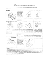
Garmin 906-2000-00 User manual

Category
Toys & accessories
Type
User manual

This manual is also suitable for

TR-1 Gold
Owner’s Manual
906-2000-00
RevH 101507
2
Rev.H 101507
Thank You
Your purchase of this TR-1 Gold outboard management system enters you in the
prestigious fraternity of anglers who count on TR-1 to control their outboard kickers.
TR-1 Autopilots is dedicated to creating the nest controls and guidance systems for the
best in boating and shing.
TR-1 Gold represents that effort. Enjoy your best shing partner ever. We’re sure you will
agree it is worth its weight in GOLD.
Table of Contents
Safety & Cautions Page 3
Parts List Page 4 & 5
Specications Page 6
Preparation Page 6 & 7
System Layout Page 8
Tools Page 9
Installation of E-H Unit (Pump) Page 9 & 10
Installation of Sensor Ball (Compass) Page 11 &12
Installation of Deckmount/ Tach Page 13
Installation of Handheld/Remote Page 14
Verify Connections Page 14
Battery Connections Page 14
Connect & Fill Hydraulic System Page 15
GPS Connections Page 18
System Functions and Features Page 19
Operating the System Page 20
Power On/Off (Deckmount) Page 21
Engaging Heading Hold Page 21
Change Heading with Remote Steer Page 21
Change Heading with RCAH (Changing Heading while in Autopilot) Page 22
GPS Steering Page 23
Setting North Page 23
Course overground Page 23
Steer to Waypoint Page 24
Orbit Waypoint Page 24
Cloverleaf Pattern Page 24
Search Pattern Page 25
Step Turns, Change Heading with Page 26
Circles, Change heading with Page 26
Reverse Page 26
MOB, change heading with Page 26
Idle/Resume Page 27
Throttle Up & Down Page 27
Zig-Zags, change heading with Page 27
Selecting Special Functions Page 28
Setup, How to make changes with Page 29
Setup Codes, Table of Page 30 & 31
Explanation of Codes Page 31 & 32
Adjusting Your Autopilot (Tuning and Setup) Pages 33-35
Rudder and Counter Rudder Gain Pages 35-37
Trouble Shooting Guide Page 39
3
Safety
You are responsible for the safe and prudent operation of your vessel.
Your TR-1 Gold Autopilot is a tool that will enhance your capability to
operate your boat and catch fish. It does not relieve you from the
responsibility for safe operation of your vessel. You must avoid hazards
to navigation and never leave the helm unattended.
You must always be prepared to promptly regain manual control of your kicker. The
autopilot and the throttle actuators can fail hard over. Learn to operate your autopilot on
calm and hazard free open water.
In case the autopilot becomes inoperable, remove the in line fuse from the battery power
cable.
The steering cylinder can be removed from its mounting bracket on the outboard in case
of hydraulic jamming.
Removing the actuating link between the stepper motor and the carburetor butterfly
crank can disable the electric throttle.
Caution:
Before drilling holes in your boat, be sure you know what you are drilling into.
Watch out for fuel tanks, electrical cables, and hydraulic hoses.
Do not run your pilot with the outboard hard on the steering stops for any
extended time or you will burn out the pump motor.
Be sure to leave the system in Standby mode when Autopilot is not
in use, or if
the kicker motor is not running.
We recommend you use only BioSOY hydraulic fluid in your autopilot hydraulics.
Keep your hands out of the outboard steering hinge area, the autopilot may steer the
motor and smash (or worse) your fingers.
2
TR-1 Gold Autopilot System Parts List
Electro-Hydraulic unit……………….…….
120-2100-00
Kinked tubing with tie wrap……………….
3 ea. Truss head machine screws #8-32x 3/4
3 ea. Lock washer nuts #8-32………………
3 ea. Truss head sheet metal screws #8 x 3/4
Sensor Ball Unit……………………………….……..
120-2200-00
Sensor Ball Bracket ………………………………….
3 ea. Pan head machine screws #8-32 x 1”…………
3 ea. Lock washer nuts #8-32…………………………
3 ea. Pan head sheet metal screws #8 x 1”…………
Sensor Ball Capture Cage...………………………….
Deck Mount Switch/Tach …………………………
120-2215-00
4
5
5
Handheld/Remote Unit...………………………….
120-2020-00
Cylinder Mounting Kit…………………
(Motor Specific)
18 feet Hydraulic Hose…………………………………
120-0013-01
Steering Cylinder………………………………………...
120-0900-00
Throttle Actuator ( Motor Specific)……………………….
1 pt. Hydraulic Fluid
120-0001-01(Bio-Soy)………………………………
6
E-H unit 6.5”H x 7” W x 5” D 8 lb
Sensor Ball 3.6” Dia. Cable length 18’ 2 lb
Remote 5”x 2.5”x 1” Cable length 18’ 1 lb
Deckmount/Tach 5/8”x 2” Cable length 6’
Battery Cable Cable length 9’
Fluid 1 pt. BioSOY Oil 1 lb
Supply Voltage 11.5 – 14.0 VDC
Maximum Current 12 Amperes
Inline Fuse ATO 20 Amp
O
p
eratin
g
Ambient Tem
p
erature 20 – 120 de
g
F
TR-1 Gold Specifications
Introduction
This manual comprises two major sections. The first section is a guide to installation of
the “onboard” components of the autopilot system on your boat. The second section is a
guide to adjusting and operating your system. Installation instructions for the throttle
actuator and steering cylinder are motor specific and are provided in separate manuals.
Preparation
You will be hard mounting three autopilot components in your boat: 1) The Electrohydraulic
Unit. 2) The Deckmount switch. 3) The Sensor ball. These components are shown in relation
to each other and to the engine mounted components in the System Layout diagram on page 8.
As indicated by this diagram, the Electrohydraulic unit and the Deckmount switch are to be
located near the kicker and the Sensor ball is to be located FORWARD OF THE CENTER
OF YOUR BOAT
Spend some time to figure out where you are going to mount all of the components before you
mount any of them. Place the components where you expect to mount them and verify you
have access to and routes for the cables and hoses that connect the components.
x Mounting Screws
Mounting screws are provided for through and blind hole applications. You may choose
to drill and tap the mounting surface.
SCREW TAP DRILL TAP CLEARANCE PILOT
#8 – 32 machine #29 .136 dia #8 –32
#8 – 32 machine 3/16
#8 s
h
eet
m
eta
l 1
/8
6
7
x Access
The Electrohydraulic Unit is the place where all the components connect together and the place where
fluid is added and fluid level is checked. Leave room for service loops in the cables and hoses.
The Deckmount switch should be easy to reach with your free hand when your other hand is on the
kicker tiller. This can be done after the initial turn on blinking setup is complete. In case of an
emergency, quick access to the deckmount switch is a good idea, by pressing the button once it will
take the autopilot to standby, allowing you to take control of the tiller handle. Pressing the button
again will return it to autopilot mode.
If you intend to hook up to GPS, the connection between the GPS and the autopilot is made at the
Sensor ball and the NMEA 0183 output on your GPS.
x Protection
Locate the Electrohydraulic unit and Sensor ball in places where they will not get submerged or
exposed to wash down.
Use a quality electrical insuating grease compound on all electrical connections (Dow Corning
#4) except the orange connectors # 1,2,3, & 4.
x Moving Parts
Hoses and cables that connect the Electrohydraulic unit to the engine mounted components
need to be free from binding and kinking. Be sure to remember your kicker moves up and down
on the lift bracket, tilts up and down, and steers lock to lock.
x Hose Length
Try to keep the hose length between the steering cylinder and the Electrohydraulic unit short. But
leave enough length for movement of Kicker (See note above on moving Parts).
x Magnetic Environment
The Sensor ball has a compass in it. Do not mount the ball near magnetic materials, magnets
(speakers and electric motors), or high current carrying wires. Small, vehicle fixed, magnetic
disturbances can be calibrated out, but moveable or changing magnetic disturbances such as anchors,
anchor chain, and wiper motors should be kept at least 24” away. A common problem is to have
mounted the ball near a glove box, and then someone puts tools in the glove box. Keep the Sensor
ball away from Air Ride seats.
x Strain Relief and Cable Protection
Do not let the connectors on the Electrohydraulic unit be the sole support for the cables connected to
them. Use the tie wraps to tie the cables down to the Electrohydraulic frame. There are several holes
in the sheet metal frame provided for this purpose.
Don’t run cables and hoses over sharp edges. Use grommets in through holes to protect the cables.
7
System Layout
Throttle
Actuator
Mounts on carburetor
on motor.
Sensor Ball: Mount
in front 1/2 of boat.
GPS connection
NMEA 0183
Battery
12V
Deckmount On/Off switch:
Mounts near kicker motor, near
transom.
Electrohydraulic Unit: Mount near
transom.
Cylinder
Cylinder Mounting Bracket: Mounts on Motor
lower end.
Tach sensor
wire:Attaches
to spark plug
wire on kicker.
1 2 3 4
Handheld/Remote
8
9
Locate the Electro-Hydraulic unit where it
it will not be subjected to water submersion
or spray from wash down.
Tools
You should gather the following tools before beginning installation. See throttle and cylinder
supplements for any additional tools that may be needed for your application.
Tools
Power Drill
#1 Phillips screw driver
.125 (1/8) or 3.17 mm dia. drill
.469 (15/32) or 11.90 mm dia. drill
Roll of masking tape
Rags
Knife
Pliers
Silicone RTV
Loctite or similar product
Electrical grease compound
(Dow Corning #4)
Installation of The Electro-Hydraulic Unit
Step one (Template)
Find the mounting template in your autopilot
documentation package. Use the wall or floor
section of the template as needed. Decide which
screw type you need. Hold the template in the
place with tape and drill right through it in the
three indicated locations. See fig.5. Remove
template and install screws in the indicated
locations on template. Tighten these 2 screws
down to 3/32” from the surface to allow enough
space for the bracket on the pump to slide behind
the screw.
Fig .4
Fig. 5
Please read the complete instructions thoroughly before starting your installation. If
you have any questions call our Tech Support line. 1-800-588-7655
9
Mounting Hydraulic Unit
10
Step Two (Locking unit in place)
Floor Mount: Set the unit on the
floor in front of screws. Slide the left
side back and engage the notch
between the hose fittings around the
left hand screw. Pivot the unit on the
left hand screw counter clockwise
until the notch under the electronics
box on the right hand side is engaged
and the remaining hole you drilled
lines up with the hole in the bottom
tab of the right hand bracket. When
the holes line up, put the last screw in
and the E-H unit is locked in place, as
shown in fig.6.
Wall Mount: Set in place by
hanging the unit on the screws.
One is the keyhole shape on the
upper left backside of E-H unit; the
other is the notched area on the
lower right side of E-H unit. Lock
E-H unit in place by lining up the
last hole on upper right hand corner.
Please note
: You will need to
remove the black plastic
thumbscrew to place the last screw,
as shown in fig.7
You may run the red and black wires to the battery box now, but do not connect to
the battery yet.
Fig. 6
Fig. 7
10
p
11
Step 3 (Adjusting Sensor Ball)
Readjust the ball if necessary and fix
it in position by tightening the
thumbscrew. See Fig 9-A. Make
sure that the wires from the Sensor
Ball are pointing straight down out
the bottom; otherwise the sensor ball
will not work properly. See Fig. 9-B
Fig. 9-A
Fig. 9-B Fig. 10-a
Note: It is important to match
your ECU wiring configuration
to the picture. Just remember
to always plug into matching
numbers from the wire to the
ECU.
Fig. 10-b
Run the wire back to the E-H unit. The wire connector from the Sensor Ball is labeled number
4. It connects to the E-H unit at connector 4, as shown in fig.10-a or 10-b. (this will depend on
your ECU wiring configuration). When you plug in the connectors, the wires go at about a 45q-
angle left of the numbers on the E-H unit (fig. 10-a) or at a 90° angle for fig 10-b. Feel the
connectors start before pushing it down.
12
12
Installation of the Deckmount and Tach
If the material you wish to mount the Deckmount
switch in is less than ¼” thick: Drill a hole 15/32
Diameter perpendicular to the surface. Unscrew
the bezel from the switch and leave one washer on
the neck. Put the switch button, with washer,
through the hole from below. Screw the bezel on
to the top and your done. Refer to Fig.11
If the surface you want to mount the Deckmount on
is thicker than ¼ inch, Drill a 19/32 hole through
the surface. Unscrew the bezel from the top of the
switch and remove the washers. Slide the switch
all the way through the hole from the backside of
the panel. Apply some silicone sealer/adhesive to
the barrel of the switch. Screw the bezel, with or
without a washer back onto the switch and slide the
switch back into the hole. It may be necessary to
tape or otherwise hold the switch in place until the
sealer/adhesive sets. Alternatively, you can make
a custom sheet metal bezel/mounting bracket for
the switch.
Step One: (Deckmount)
Fig. 11
Step Two (Tach)
The Tach is the portion of the cable with a white antenna
end. The antenna end needs to be installed into your
outboard motor. The wire connector from the deck
mount/Tach switch is labeled number 1. It connects to the
E-H unit at connector number 1. Route the Tach portion of
the wire from the E-H unit back to the motor. Remove the
outboard cover. Route the cable through the grommets on
the front of your motor, then route the cable around the
motor to the spark plug wires. You will need to lay the
white or antenna end of the cable along side
of one of the
spark plug wires in your motor. Keep the antenna end at
least 1” from either end of spark plug wire. Do not
stick the end of the wire into the boot of the spark plug
wire. Use tie-wraps to attach the antenna end of cable to the
Spark plug wire. (Fig. 11-A)
(After installation of your Autopilot, you will need to verify
your tach. Please refer to page 31, paragraph 2 for more
information).
Note: Route the cable for the tach on the
opposite side of the kicker motor that you route
the throttle actuator wire
.
Fig. 11-A
13
Fig. 12
Installation of the Handheld/Remote
Connect the Remote cable to the ECU unit at
connector number 3. Strain Relieve the cable.
One place to do this is the bottom right hand side
of the ECU unit. See Fig. 12. This will help
protect the Remote cable from being pulled out
of the connector on the ECU unit and possibly
damaging unit. If you need to drill a hole in the
boat for the cable be sure to put a grommet in the
hole to protect cable from the sharp edges.
Installation of the Cylinder Kit and Throttle Actuator
Refer to the manuals supplied with the throttle and steering cylinder kits, and install these parts
before continuing with the procedures that follow. If you do not use the throttle actuator, it is
recommended that you coat #2 pico connector with a grease to protect it from corrosion.
Battery Connection Installation
Connections
At this point, all electrical connections to the
Electrohydraulic unit are complete. Some
ECU wiring configurations are slightly
different see fig. 13-a and fig.
13-b for your variation. Verify these
connections
as follows:
Deck mount #1 To ECU connector #1
Throttle #2 To ECU connector #2
Handheld #3 To ECU connector #3
Sensor Ball #4 To ECU connector #4
Now hook up the battery connections. We recommend that you
connect the battery cable directly to the battery. Connect the
ground side first. Connect the black wire to negative (-) side of
the battery. Connect the orange wire to the positive (+) battery
terminal.
Note: Do not be alarmed if connection sparks when connected to
battery, you are charging a capacitor inside the unit.
Do not cut out or eliminate the fuse portion on your battery
cable, it is there to protect your system and may void your
warranty if removed.
If you unplug the battery cable be sure to replace the tie wrap
around connectors to prevent them from separating.
Fi
g
.13-a
Fi
g
.13-b
14
15
Connect and Fill the Hydraulic System
Before you start………
x The fittings in the electro hydraulic unit (Pump unit) and the Cylinder are barbed hose fittings.
It is important that you push the hose completely over the barbs. Use some fluid to lube the inside
of hose before pushing them on. It will make the process slightly easier.
x This process may be a little messy so keep a few rags handy. Safety glasses
are also a good idea.
x If you haven’t already, loosen the steering tension adjustment on your motor to the minimum
setting. The motor should turn very easily. (If necessary refer to your outboard motor’s
owner’s manual).
x As with all hydraulic systems, it is very important to keep any dirt or debris from entering
the system.
Step One
Remove the Left side of the kinked clear shipping tube from
the E-H unit. Keep the kinked clear tube (with the tie wrap)
on the Right barbed fitting (It will act as a plug).Fig.A
Step Two
Run a continuous
section of black rubber hose from the Left
E-H fitting, out the back of the boat to the cylinder and back
into the boat to the pump. Do not cut the hose at this time.
See.Fig. B
Fig. A
Fig. B
15
Fig A
16
Step Three
Arrange the hose at the cylinder end so that none will kink and they
are hanging free. Put a piece of tape on the right hose at the cylinder
end to identify it. You will need to know this when it’s time to
connect the hose to the cylinder. See Fig.14.
Step Four
Get into the boat close to the E-H unit. Bring the Remote Handheld,
uid, and some rags. Remove the screw that locks the E-H unit in
place so that you can move the unit around. Remove the tank plug by
unscrewing counterclockwise and remove. Note the tank has two
uid level lines on it. The upper line is the full line and the lower line
is the low uid line.
Step Five ( Purge Air)
Take the open end of the continuous loop of black hose,
and insert it into the tank as shown in Fig. 15. Be sure
that the other end of black hose is secure on the left
barbed tting on the E-H unit. Also make sure that
the clear kinked hose is also secure on the right barbed
tting. (Use of tie wraps may be necessary)
Turn the pilot on by momentarily pressing and releasing
the deckmount switch. When the Stby LED quits
blinking, press the top button on the remote (Auto/Stby)
the Auto Led will be lit. Holding the tube in the tank
press the Left Straight Arrow. Refer to g. 15. The
uid level will go down. Let the button up and place
system in STBY when the uid is low and rell the
tank. (Do not press the Straight Right Arrow Button,
you will blow the clear tube off the right side and
create a hydraulic uid mess)
You may need to ll the tank several times. Keep the
hose submerged in the tank uid and keep pumping until bubbles stop
appearing in the tank.
Turn the system to standby by momentarily pressing the top
button (AUTO/STBY) on the handheld. Turn the unit off by
pushing in the deckmount button and hold until the lights are
out (about to the count of 5). Remove the hose from the tank,
keeping your thumb over hose to prevent air from entering or
losing uid. Insert the tank plug, tting it securely into the top
of tank. Tilt the tting end of the E-H unit back and remove
the kinked shipping hose from the E-H. Now push the rubber
hose onto the right tting pushing rmly until fully engaged
over barbs. Install the Two (2) Hose clamps over the hose and
barbed ttings at the manifold and tighten. See Figure 15-a.
You will need the clear shipping tube again in the next step
so don’t throw it away yet.
Fig. 14
Fig. 15
Fig. 15-a
Step Six (Fill Cylinder)
You will need the motor in the down position and
the cylinder fittings pointing straight up.
Disconnect the rod end of the cylinder from its
mount. Find the kinked piece of tubing that you
removed in step one. Remove the tie wrap and cut
the tubing in half. Push one half on each cylinder
barbed fitting. Open the fluid bottle. Insert pieces
of tubing into the fluid. They need to go to the
bottom of the bottle. Now hold the tubing in the
bottle with one hand and pull and push the rod in
and out of the cylinder until you stop seeing air
bubbles in the hose. Refer to fig. 16
Fig. 16
Fig. 17
Slide the rod into the cylinder as far as it will go. Now remove the short clear hose from the cylinder and
drain the fluid from the tubing into the bottle. Be sure both cylinder fittings are full to the top. Point the
rod end of the cylinder toward the pin that engages it but leave it pushed into the cylinder.
Step Seven (Correctly connect the hose)
At the cylinder, kink the black hose (bend it
over sharply and use a tie wrap to pinch hose
shut). See Fig. 17. Cut the hose as shown just
above the tie wrap and keep a thumb over the
right side to keep the fluid in the hose. Keep
the hose full to the brim and push the right
hose (hose that has tape) onto the right cylinder
fitting as shown in Fig.17-A
Cut the tie wrap on the left hose and insert it o
n
the left fitting on the cylinder as shown in
Fig.17-B. Reconnect the cylinder rod end.
Fig. 17-A Fig. 17-B
17
17
Step Eight (Check hose t)
Check to see that the hose is free to move back and forth with motor. Tie wrap as
necessary to hold hose in place. See Fig. 18
Step Nine (Hose Clamp)
Place hose clamps over hose and ttings at cylinder end. Fig. 18-a
Step Ten (Top off the system)
Manually turn the motor back and forth several times. Air bubbles trapped in the
tubing may cause the uid level in the tank to surge when the tiller is moved fast.
The more the tiller is cycled back and forth, the more air is purged from lines. Top
off the tank with uid when the surge is reduced. Replace the tank plug. Remount
the pump unit following the instructions on page 10, making sure all screws are
tight.
Verify Proper Installation
Press the deck mount switch to turn the system on. Put the unit in AUTO
mode. Press and hold the Straight Left Arrow button on the Remote. The
kicker will steer to the port. Press and hold the Straight Right Arrow
button on the Remote and the kicker will steer to starboard. Turn the motor
several times in each direction to verify that hose connections are tight and
that you have no binding of hoses or cables.
Get in position to see the kicker carburetor and the throttle actuator you installed, then press and hold the Up Arrow
button. The actuator should open the carburetor throttle. Press and hold the Down Arrow button. The actuator should
run the carburetor to idle. Pushing and releasing these buttons quickly moves the throttle by small amounts. Holding
them down changes the throttle by large amounts. Move the throttle to mid-travel and then press the IDLE/RES button.
The throttle should go to idle. Press the button again and the throttle should go back to the mid-travel position.
!!!! You will need to calibrate the Compass of your Autopilot, and will need to tune the
Autopilot to your boat and motor conguration. Please see page 33, adjusting your Autopilot
for Heading Hold operations on your Boat.
Check to see that your GPS transmits NMEA 0183 messages $GPRMB (RMB),and $GPRMC (RMC) before you hook
your GPS to the autopilot. These are the messages the autopilot must receive in order to steer with the GPS. Your GPS
NMEA output wires will usually be bundled with other conductors in the GPS cables. Look in your GPS manual for
instructions relating to NMEA output from the GPS to other devices. The GPS manual should identify two wires that
are named something like NMEA out (+) and NMEA out (-). Connect the NMEA out (+) to the red (+) and the NMEA
out (-) to the white (-) conductors in the stub cable with the blue tip at the Sensor ball. You will need to strip some of
the jacket from the blue tipped cable in order to get to the red and white conductors. 22 or 24 gage twisted pair wiring is
recommended for connecting this circuit. (See page 23 for more information on GPS.) You will need to calibrate your
compass and Set North in order for GPS functions to work. See pages 23 & 35
18
GPS Connections
This section of this document provides you with information that will let you take advantage of
your TR-1 Gold autopilots' capabilities. We have made every effort to minimize the pain in
getting you up to speed as a user of the TR-1, however, programmable devices such as your TR-
1, are often difficult to learn to use and to program. We recommend that you do not take your
fishing tackle with you on your first trip with your new autopilot. Take a few hours on a nice
day to get your system setup and familiarize yourself with its operation, then your first fishing
trip with the unit will really have you smiling.
This manual is laid out in sections that are, as best we can make them, self contained. We start
with the features and functions available and fundamentals of how the system works, then how to
operate the basic functions, and finally how to get into the fine adjustments.
Some of you will find that this manual is lacking in depth and clarity, and for this we apologize.
Please do not hesitate to call us for interpretation and other help you may need.
Introduction to Operation and Adjustments
System Functions And Features
The TR-1 is, at its core, a heading hold autopilot. It steers the kicker to maintain a constant
magnetic heading. The autopilot measures magnetic heading with a flux gate compass and
receives rate of turn information from a vibrating beam rate sensor (gyroscope). The autopilot
computer forms a rudder rate command from a combination of the compass, gyro, and engine
tachometer signals. This rudder rate command is calculated and sent to the pump controller in
the electrohydraulic unit electronics 20 times each second. The pump control electronics
servos the pumping speed and direction to match the rudder rate command from the autopilot.
The autopilot is designed to disconnect from the steering cylinder when it is off or in standby.
It does this with a bypass valve that shunts fluid from the steering cylinder around the pump
when the bypass valve is open.
Beyond the basic heading hold function, the autopilot provides for several other modes of
automatic and manually controlled steering functions. These are listed below.
1. Rudder Command / Attitude Hold (RCAH). RCAH is the primary means for changing the
boats heading manually.
2. Remote steer. Remote steering is used for electrically steering the kicker without feedback
from the gyro or compass.
3. Step turns. The autopilot will execute predetermined fixed angle turns in this mode.
4. Circles. The autopilot will turn in circles of predetermined duration.
5. Zigzags. The autopilot will steer a zigzag course with predetermined angle and duration.
19
6. Man Overboard. The autopilot will execute a turn to the reciprocal course and pass near the maneuver
initiation point.
7. GPS steering. (Some GPS units may not support these features.)
7a. The autopilot will steer to a waypoint or series of waypoints.
7b. The autopilot will orbit a waypoint.
7c. The autopilot will steer a 3 leaf clover pattern over a waypoint.
7d. The autopilot will steer a spiral search pattern around a waypoint.
7e. The autopilot will steer to constant course over ground.
8. Reverse. The autopilot will attempt to execute any of the above steering functions while the boat is
backing.
The TR-1 system includes an electric throttle mechanism for remote control of the kicker throttle
valve. The throttle butterfly valve is actuated by a lead screw and stepper motor. The stepper advances
or retracts the lead screw in 1/1000 inch steps as commanded by the remote control pushbuttons. On
system power down, the stepper is commanded to take the butterfly valve to its' closed throttle position.
The throttle system has an Idle/Resume feature that provides for single button push reduction of throttle to
idle and subsequent button push resumption of the initial RPM.
Operating The System
Most of the operation of the autopilot is accomplished through the remote control and the deckmount
switch. To make things easy to talk about we will name the buttons as shown in the picture of the handheld/
remote below.
Autopilot/Standby
Button
Straight Right Arrow
Button
Up Arrow Button
Down Arrow Button
Bent Right Arrow Button
Straight Left Arrow
Button
GPS (Select Load)
Button
Bent Left Arrow
Button
Idle/Resume
Button
Setup Button
Almost all of the buttons in the systems have multiple functions, and many functions are accomplished by
button push sequences or by pushing more than one button at a time. The steering and throttle modes are not
all available simultaneously. The Idle/Resume , Bent Left Arrow, and Bent Right Arrow buttons are
sometimes referred to as “special function” buttons in the following text.
20
  • Page 1 1
  • Page 2 2
  • Page 3 3
  • Page 4 4
  • Page 5 5
  • Page 6 6
  • Page 7 7
  • Page 8 8
  • Page 9 9
  • Page 10 10
  • Page 11 11
  • Page 12 12
  • Page 13 13
  • Page 14 14
  • Page 15 15
  • Page 16 16
  • Page 17 17
  • Page 18 18
  • Page 19 19
  • Page 20 20
  • Page 21 21
  • Page 22 22
  • Page 23 23
  • Page 24 24
  • Page 25 25
  • Page 26 26
  • Page 27 27
  • Page 28 28
  • Page 29 29
  • Page 30 30
  • Page 31 31
  • Page 32 32
  • Page 33 33
  • Page 34 34
  • Page 35 35
  • Page 36 36
  • Page 37 37
  • Page 38 38

Garmin 906-2000-00 User manual

Category
Toys & accessories
Type
User manual
This manual is also suitable for

Ask a question and I''ll find the answer in the document

Finding information in a document is now easier with AI