PROLINK Modem ADSL Modem/Router User manual
- Category
- Routers
- Type
- User manual

1
User's Manual
Hurricane 9000
Version 1.0
ADSL Modem/Router

2
Contents
Section One: Introduction ......................................................... 4
1.1 System Requirements.............................................. 4
1.2 Features Summary .................................................. 4
Section Two: Connect the Modem/Router............................... 6
2.1 This Package Contents............................................. 6
2.2 Product View............................................................ 7
2.3 Hardware Installation............................................... 8
2.4 Network Connections .............................................. 9
2.5 LED Indicators ......................................................... 9
Section Three: Configure the PCs ............................................. 10
3.1 Configure your PC .................................................. 10
3.2 Verify the link between your PC and Router ............. 11
Section Four: Web-Based Management .....................................12
4.1 Login ......................................................................... 12
4.2 Quick Setup ............................................................... 13
4.3 ADSL Line Status ..................................................... 15
4.4 WAN/LAN Status ..................................................... 15
4.5 PPP Status ................................................................ 16
4.6 System Log .............................................................. 16
4.7 Advanced Setup ..................................................... 17
4.7.1 LAN/DHCP ..................................................... 17
4.7.2 Port Forwarding ............................................ 18
4.7.3 NAT Configuration ......................................... 19
4.7.4 Bridge Filtering ............................................... 20
4.7.5 Misc Configuration ......................................... 21
4.7.6 Route Table .................................................... 23
4.7.7 Admin Password .......................................... 23
4.7.8 Firmware Update .......................................... 24
Section Five: USB Driver Installation .......................................... 25
Section Six: Troubleshouting and FAQs .................................. 26
Prolink Technical Support ............................................................. 30

3
The information contained in this manual has been verified at the time
of this manual's printing. The manufacturer reserves the right to make
any changes and improvements in the product described in this
manual at any time and without notice.
All registered trademarks are the property of their respective owners.
Copyright © 2002 All rights reserved. No reproduction of this docu-
ment in any form is permitted without prior written authorization from
the manufacturer.

4
Section One - Introduction
The Hurricane 9000 provides Full rate (ANSI and G.DMT) as well
as G.lite ADSL standards line support, and can be connected to
PC through Ethernet or USB . This product supports bridge
feature set for the integration of ADSL service into corporate or
home LAN and WAN.
1.1 System Requirements
Before connecting the Hurricane 9000 to your PC, make
sure your sysytem is equipped with the Ethernet NIC card or USB
port and TCP/IP protocol.
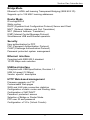
1.2 Features Summary
ADSL Compliance
Compliant with ADSL standards:
ANSI T1.413 Issue 2, ITU G.dmt (G.992.1) and G.lite (G.992.2).
ADSL over POTS (Annex A) and ADSL over ISDN (Annex B)
DMT modulation and demodulation
Full-rate adaptive modem
Maximum downstream rate of 8 Mbps
Maximum upstream rate of 1 Mbps
Tone detection for low power mode
Supports splitterless ADSL implementation
Supports Dying Gasp (optional)
ATM Protocols
WAN mode support: PPP over ATM and over Ethernet. (RFC 2364/2516)
LAN mode support: bridged/routed Ethernet over ATM (RFC 1483) and
Classical IP over ATM (RFC 1577)
ATM Forum UNI 3.1/4.0 PVC
Up to 8 VCs (Virtual Circuits)
ATM SAR (Segmentation and Reassembly)
ATM AAL5 (Adaption Layer type 5)
OAM F4/F5
Section One: Introduction

5
Section One: Introduction
Bridge Mode
Ethernet to ADSL self-learning Transparent Bridging (IEEE 802.1D)
Supports up to 128 MAC learning addresses·
Router Mode
IP routingñRIPv2
Static routing
DHCP (Dynamic Host Configuration Protocol) Server and Client
NAPT (Network Address and Port Translation)
NAT (Network Address Translation)
ICMP (Internet Control Message Protocol)
Simultaneous USB and Ethernet operation·
Security
User authentication for PPP
PAP (Password Authentication Protocol)
CHAP (Challenge Authentication Protocol)
Password protected system management
Ethernet interface
Compliant with IEEE 802.3 standard
10/100 Mbps auto selection
USB host interface
Compliant with USB Specification, Revision 1.1
USB full speed (12 Mbps)
Vendor specific descriptors
HTTP Web-based management
Firmware upgrade via FTP
Customizable Web pages
WAN and LAN side connection statistics
Configuration of static routes and Routing table
Configuration of NAT/NAPT
Password protected access
Selection of Bridge or Router Mode
PPP user ID and password
Configuration of VCs (Virtual Circuits)

6
Section Two - Connect the Modem/Router
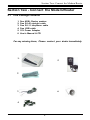
2.1 This Package contents
1. One ADSL Router modem
2. One RJ-45 straight cable
3. One RJ-11 telephone cable
4. One USB cable
5. 12V Power Adaptor
6. User's Manual &
CD
For any missing items, Please contact your dealer immediately.
Section Two: Connect the Modem/Router
5
6
1.
2
3
4

7
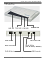
RJ11 Line Jack
Reset Button
(Set to factory Default)
POWER LED
LAN LED
2.2 Product View
Section Two: Connect the Modem/Router
TX/RX LED
Power Switch
Power Connector
USB Connector
RJ45 LAN Jack
LINK LED

8
Section Two: Connect the Modem/Router
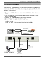
2.3 Hardware Installation
The following steps instruct you to install the Hurricane 9000 for
one computer. For more than one computer, please refer to 2.4
Network Connection.
1. Plug the end of the Ethernet cable into the LAN Jack of the Hurricane
9000.
2. Plug the other end of the Ethernet cable into your computer’s RJ45
Jack of Ethernet card.
3. Connect the Power adaptor to the Power Connector.
4. Plug the telephone cable into the Line Jack .
5. Plug the other end of the telephone cable into
i) a Main Socket .
ii) OR the Jack of the two-way Microfilter labeled DSL.
2-way
Power Adaptor
RJ-45
USB Cable
(Optional)
OR
Telephone
Computer
Main Socket ADSL Line
Microfilter

9
Section Two: Connect the Modem/Router
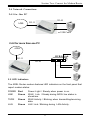
2.4.2 for more than one PC
2.4 Network Connections
2.4.1 for One PC
......
ADSL
RJ-11
ADSL
RJ-45
HUB/Switch
or USB Cable
2.5 LED Indicators
The ADSL Router modem features LED indicators on the front panel that
report modem status:
POWER Red Power Light / Steady when power is on.
LINK Green WAN Link / Steady during ADSL line status is
showtime.
TX/RX Green WAN Activity / Blinking when transmitting/receiving
data.
LAN Green LAN Link / Blinking during LAN Activity.
RJ-11
RJ-45

10
Section There: Configure the PCs
Section Three - Configure the PCs
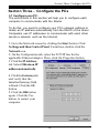
3.1 Configure your PC.
The instructions in this section will help you to configure each
computer to communicate with the Router.
To do this, you need to configure your PC’s network settings to
obtain an IP address automatically from the DHCP of the router.
Computers use IP addresses to communicate with each other
across a network, such as the Internet.
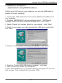
1. Go to the Network screen by clicking the Start button. Click
Settings and then Control Panel. From there, double-click the
Network icon.
2. On the Configuration tab, select the TCP/IP line for the
applicable Ethernet adapter. Then, click the Properties button.
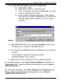
3. Click the IP Address
tab. Select Obtain an IP
address automatically.
4. Click the Gateway tab,
and verify that the
Installed Gateway field
is blank. Click the OK
button.
5. Click the OK button
again. Click the Yes
button to restart your
computer.

11
3.2 Verify the link between your PC and Router
a) From start > Run
b) Enter ping 10.0.0.2 –t and click OK
c) If the connection has been established, You will
receive reply from the router.
d) If you receive “Request timed out”, that means
the link has not been established, pls. check the
network cable and IP address. (or try to restart
your PC)
Notes:
1. Under MS-DOS mode, you can type ipconfig to check your
IP address. (to renew IP: ipconfig /renew )
2. You may have to disable the proxy settings on your Internet
browser .
Tools>Internet Options>Connection>LAN
settings>Disable Proxy Server
3. Make sure that your browser is set to connect directly .
For Internet Explorer, click Tools, Internet Options, and then the
Connection tab. Make sure that Internet Explorer is set to Never
dial a connection.
For Netscape Navigator, click Edit, Preferences, Advanced, and
Proxy. Make sure that Netscape Navigator is set to Direct
connection to the Internet.
Section There: Configure the PCs

12
Section Four: Web-Based Management
Section Four Web-Based Management
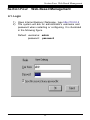
4.1. Login
1) Open Internet Explorer /Netscape , type http://10.0.0.2
2) The system will ask for administrator’s username and
password when restarting or configuring. It is illustrated
in the following figure.
Default username: admin
password: password

13
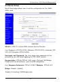
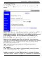
4.2 Quick Setup
Section Four: Web-Based Management
Quick Setup page allows user to set the configuration for the WAN/
ADSL ports.
VPI/VCI: ATM VC of local ADSL Internet Service Provider.
(e.g. Singapore: VPI/VCI=0/100; Malaysia: VPI/VCI=0/35; Indonesia: VPI/
VCI=1/33; SriLanKa: VPI/VCI=8/35)
Username and Password: the user name and password will be
provided by your ISP when applying for PPP ADSL service.
Encapsulation: PPPoA, PPPoE, 1483 router, IPoA and 1483 Bridge.
Please selct one according to your local ISP designation.
(e.g. Singapore/Indonesia: PPPoA VCMUX; Malaysia: PPPoE LLC)
Bridge: Disable. (default)
Enable it if selecting 1483 Bridge mode.

14
Section Four: Web-Based Management
Static WAN IP Configuration (Optional)
If you are using 1483 Routed IP or Classical IP over ATM,
please enter the IP address, Subnet Mask and Gateway
(Provided by your local ISP)
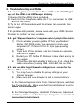
Disconnect Timeout: The Disconnect Timeout allows users to set the
specific period of time to disconnect from the ISP. The default is 0, which
means never disconnect from the ISP.
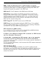
Q: If the PPP is disconnected after the Disconnect Timeout and
how can I reconnect it.
A: You have to go to the PPP Status under Admin Privileged
column, choose the correct PVC and Connect option, and then
click Execute to restart a new PPP secession.
B. OR you can enable PPP reconnect on WAN access under Misc
Configuration, the PPP will be automatically reconnected when an URL is
entered in the browser (packet interested in going out to the WAN).
Automatic Reconnect: When it is checked, it will maintain the PPP
connection all the time. If the ISP shut down the PPP connection, it will
automatically reconnect PPP session.
Please remember to click on "Submit" Button to reboot and
take effect.

15
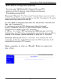
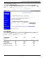
4.3 ADSL Line Status.
The ADSL Line Status page shows the ADSL physical layer status.
Section Four: Web-Based Management
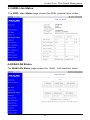
The WAN/LAN Status page shows the WAN , LAN interface status.
4.4 WAN/LAN Status.

16
4.5 PPP Status.
The PPP Status page shows the status of PPP for each PVC Connect
and Disconnect allows users to manually connect/disconnect the PPP
connection for one PVC.
The System Log page shows the events triggered by the system.
4.6 System Log.
Section Four: Web-Based Management

17
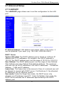
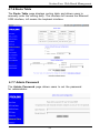
4.7 Advanced Setup.
4.7.1 LAN/DHCP.
The LAN/DHCP page allows user to set the configuration for the LAN
port.
IP Address/Subnet: LAN address and subnet mask of the router. It
can be specified if you need. (e.g. 192.168.0.1/255.255.255.0)
DHCP Server
System Allocated: The DHCP address pool is based on LAN port IP
address plus 12 IP addresses. For example, the LAN IP address is
10.0.0.2; the DHCP address pool is at the range of 10.0.0.3 to 10.0.0.14
User Defined: The DHCP address pool is at the range of User Defined
Start Address and User Defined End Address Address. The maximum
pool size can be 253 IP addresses: 255 total IP addresses - 1 broadcast
address - 1 LAN port IP address.
Lease time: The Lease time is the amount of time of a network user will
be allowed to connect with DHCP server. If all fields are 0, the allocated
IP addresses will be effective forever.
User mode: Under the Single User mode, the DHCP server only
allocates one IP address to local PC. Under the Multiple User mode, the
DHCP server allocates the IP addresses spececified bye the DHCP
address pool.
Section Four: Web-Based Management

18
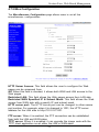
4.7.2 Port Forwarding
Section Four: Web-Based Management
The Port Forwarding page allows users to set the configuration of
Virtual Server. If any specific local PCs need to be mapped to the UDP/
TCP port on WAN side, please input the mappings here.
For Example,
If you want to forward FTP to your 10.0.0.20 server (set to static IP):
Public Port :21 Private Port:21 Port Type: TCP
Host IP Address: 10.0.0.20
Customized Port TCP UDP
Application
Web server 80 Yes Yes
FTP server 21 Yes No
SMTP (outgoing) 25 Yes Yes
POP3 (incoming) 110 Yes Yes

19
Section Four: Web-Based Management
4.7.3 NAT Configuration
The NAT Configuration page allows users to set the configuration for
the Network Address Translation.
NAT Configuration
The NAT option only maps single WAN IP address to the local PC IP
address. It is peer-to-peer mapping. (1x1) For each PVC, only one local PC
IP address can be associated with each WAN PVC. Click the link Session
Name Configuration to add the session name for each PVC.
Q: Since only one PVC is mapped to one local PC IP address, why can I
input more than one IP address for one NAT session?
A: Even though you can, only the first IP address of each session takes effect.
NAPT Configuration
The NAPT option maps the IP address and UDP/TCP port ID of the WAN
PVC to the IP address and UDP/TCP port ID of the local PCs. (1xN). It is the
multiple-mapping mechanism. More than one local PC can be associated
with one WAN PVC.
Dynamic NAPT:The default setting is Dynamic NAPT. It provides dynamic
Network Address Translation capability between LAN and multiple WAN
connections, and the LAN traffic is routed to appropriate WAN
connections based on the destination IP addresses and Route Table. This
eliminates the need for the static NAT session configuration between
multiple LAN clients and multiple WAN connections. When the Dynamic
NAPT is chosen, there is no need to configure the NAT Session and NAT
Session Name Configuration.

20
Section Four: Web-Based Management
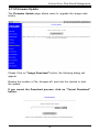
4.7.4 Bridge Filtering
The Bridge Filtering page allows users to set the configuration of IP
filtering.
Source MAC: When the bridge filtering is enabled, enter the Source MAC
address, select Block and click Add. Then all incoming WAN and LAN
Ethernet packets matched with this source MAC address will be filtered out.
If the Forward is selected, then the packets will be forwarded to the
destination PC.
Destination MAC: When the bridge filtering is enabled, enter the
Destination MAC address, select Block and click Add. Then all incoming
WAN and LAN Ethernet packets matched with this destination MAC address
will be filtered out. If the Forward is selected, then the packets will be
forwarded to the destination PC.
Type: Enter the hexadecimal number for the Ethernet type field in
Ethernet_II packets.
For example,
If you want to block MAC address: 000002fa6fab to access the internet:
Source MAC: 000002fa6fab Type: 0800
Remark: to check your PC's MAC address, ipconfig /all under DOS mode.
Type 0800: Internet Protocol, for others, pls. check with your administrator.
Page is loading ...
Page is loading ...
Page is loading ...
Page is loading ...
Page is loading ...
Page is loading ...
Page is loading ...
Page is loading ...
Page is loading ...
Page is loading ...
-
 1
1
-
 2
2
-
 3
3
-
 4
4
-
 5
5
-
 6
6
-
 7
7
-
 8
8
-
 9
9
-
 10
10
-
 11
11
-
 12
12
-
 13
13
-
 14
14
-
 15
15
-
 16
16
-
 17
17
-
 18
18
-
 19
19
-
 20
20
-
 21
21
-
 22
22
-
 23
23
-
 24
24
-
 25
25
-
 26
26
-
 27
27
-
 28
28
-
 29
29
-
 30
30


PROLINK Modem ADSL Modem/Router User manual
- Category
- Routers
- Type
- User manual
Ask a question and I''ll find the answer in the document
Finding information in a document is now easier with AI
Related papers
Other documents
-
Belkin F5D5630AU User manual
-
-
 Ozenda AR4505GW User manual
-
MicroNet SP3351 User manual
-
-
Edimax Technology AR-6024 User manual
-
Planet ADE-4000 User manual
-
 Planet Technology ADW-4100 User manual
-
 Planet Technology ADE-3000 User manual
-
 Planet Technology ADE-3000 User manual


