Page is loading ...

INSTRUCTION MANUAL
HI98194,
HI98195, HI98196
Multiparameter Meters
pH/mV, ORP, EC, TDS, Resistivity,
Salinity, Seawater σ, Dissolved Oxygen,
Atmospheric Pressure & Temperature

Thank you for choosing a Hanna Instruments product.
Please read this instruction manual carefully before using the instrument.
This manual will provide you with the necessary information for correct
use of the instrument, as well as a precise idea of its versatility.
If you need additional technical information, do not hesitate to e‑mail
us at [email protected] or view our worldwide contact list at
www.hannainst.com.
Dear Customer,
All rights are reserved. Reproduction in whole or in part is prohibited without the written consent of
the copyright owner, Hanna Instruments Inc., Woonsocket, Rhode Island, 02895, USA.

3
TABLE OF CONTENTS
5
5
7
8
10
15
17
19
23
6
10
11
16
18
22
24
25
26
26
28
CHAPTER 1 - INTRODUCTION
Preliminary Examination .....................................................................................................
Model Identification ...........................................................................................................
General Description ............................................................................................................
Display and Keypad Description ...........................................................................................
CHAPTER 2 - QUICK START
Sensor and Probe Installation ..............................................................................................
Basic Operation .................................................................................................................
Help Function .....................................................................................................................
CHAPTER 3 - SPECIFICATIONS
System Specifications ..........................................................................................................
Probe Specifications ............................................................................................................
Sensor Specifications ...........................................................................................................
CHAPTER 4 - PROBE INSTALLATION
Sensor Descriptions .............................................................................................................
Sensor Preparation/Activation ..............................................................................................
Sensor Installation ..............................................................................................................
CHAPTER 5 - INITIALIZATION AND MEASUREMENT
Battery Installation .............................................................................................................
Meter Initialization .............................................................................................................
Measurement Mode ............................................................................................................
Setup Menu Structure .........................................................................................................
CHAPTER 6 - PARAMETER SETUP MENU
Select Parameters ...............................................................................................................
Parameter Units ..................................................................................................................
Parameter Coefficients .........................................................................................................

4
29
31
35
41
30
34
38
42
46
50
47
52
54
45
46
49
50
53
56
57
TABLE OF CONTENTS
CHAPTER 7 - CALIBRATION MODE
Calibration Mode.................................................................................................................
Quick Calibration ................................................................................................................
pH Calibration ....................................................................................................................
Relative mV Calibration .......................................................................................................
Dissolved Oxygen Calibration (HI98194, HI98196 only) ........................................................
Conductivity Calibration (HI98194, HI98195 only) ................................................................
Temperature Calibration ......................................................................................................
Atmospheric Pressure Calibration ..........................................................................................
CHAPTER 8 - SYSTEM SETUP
Meter Setup .......................................................................................................................
Probe Setup .......................................................................................................................
CHAPTER 9 - STATUS
Meter Status ......................................................................................................................
Probe Status ......................................................................................................................
GLP Data ...........................................................................................................................
CHAPTER 10 - LOGGING MODE
Logging Mode ....................................................................................................................
Logging Menu Structure ......................................................................................................
Logging On Meter ...............................................................................................................
Log Recall ..........................................................................................................................
Log Notes ..........................................................................................................................
CHAPTER 11 - PC CONNECTION
PC Connection ....................................................................................................................
CHAPTER 12 - TROUBLESHOOTING / ERROR MESSAGES
Troubleshooting/Error Messages............................................................................................
APPENDIX
A ‑ PROBE MAINTENANCE....................................................................................................
B ‑ PROBE DEPLOYMENT ....................................................................................................
C ‑ ACCESSORIES ...............................................................................................................
42
59
61

5
Remove the instrument from the packing material and examine it carefully to make sure that no
damage has occurred during shipping. If there is any damage, please contact your local Hanna
Instruments Office.
METERS WITH PROBES ‑ packaged together in a sturdy carrying case with:
• HI7698290 calibration beaker
• HI9828‑20 calibration solution (230 mL)
• USB cable
• 1.5V AA batteries (4 pcs.)
• probe maintenance kit
• appropriate probe shield
• specified sensors
• Instruction Manual and Quick Reference Guide
• Certificate
Note: Save all packing materials until you are sure that the instrument functions correctly.
Any damaged or defective items must be returned in their original packing material with
the supplied accessories.
Chapter 1 - INTRODUCTION
PRELIMINARY EXAMINATION
MODEL IDENTIFICATION
HI98194 pH/mV, ORP, EC, TDS, Resistivity, Salinity, Seawater σ, Dissolved Oxygen,
Atmospheric Pressure and Temperature Multiparameter meter with HI7698194
probe.
HI98195 pH/mV, ORP, EC, TDS, Resistivity, Salinity, Seawater σ, Atmospheric Pressure and
Temperature Multiparameter meter with HI7698195 probe.
HI98196 pH/mV, ORP, Dissolved Oxygen, Atmospheric Pressure and Temperature
Multiparameter meter with HI7698196 probe.

6
GENERAL DESCRIPTION
HI9819X is a portable logging multiparameter system (instrument, probe) that monitors up to 14
different water quality parameters (7 measured, 7 calculated).
The microprocessor‑based intelligent multisensor probes allows measurement of many water quality
parameters such as pH, ORP, dissolved oxygen, conductivity and temperature with data logging. The
system is easy to setup and easy to use.
The HI9819X features a graphic, backlit display that automatically sizes the digits to fit the screen
with on‑screen graphing capability. Each parameter is fully configurable.
HI9819X was designed to withstand harsh environments and is the ideal solution for field measure‑
ments of lakes, rivers and sea.
The meter meets IP67 standards (30 minute immersion at a depth of 1 m) and the multisensor probe
meets IP68 standards (continuous immersion in water).
Main features of the HI9819X systems:
• Rugged meter and probe
• Easy to use
• Measure up to 14 parameters and display of up to 12 parameters
• Waterproof protection (IP67 for the meter and IP68 for the probe)
• Graphic LCD with backlight
• Built‑in barometer for D.O. concentration compensation (HI98194, HI98196 only)
• Quick calibration feature
• Measurement check to eliminate any erroneous readings
• Auto recognition of probe and sensors
• Log‑on‑demand and automatic logging (up to 45,000 samples) on meter for all parameters
• Graphical display of logged data
• USB interface for PC communication
• Auto‑ranging for EC readings (HI98194, HI98195 only)
• Good Laboratory Practice feature, the last 5 calibrations are automatically stored
• Field‑replaceable sensors with color coded caps
• Meter is powered with alkaline batteries

7
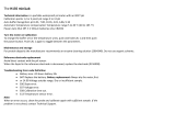
DISPLAY AND KEYBOARD DESCRIPTION
1. Graphic LCD
2. Battery level indicator
3. Softkeys
4.
On/Off key: turn the meter on and off
5.
Lamp key: turn the backlight on and off
6. Alphanumeric keyboard: insert alphanumeric codes
7.
/ Arrow keys: scroll the displayed options/message
8. HELP key: obtain information about the displayed screen
9. ESC key: return to the previous screen
10. Softkey functions defined on display

8
Chapter 2 - QUICK START
• Sensor O‑Rings must be lubricated with the supplied grease prior to installation.
• HI769819X probes have 2 or 3 sensor connectors sockets identified with color‑coded triangles:
• Connector 1 (red): For either pH/ORP, pH sensor
• Connector 2 (white): For dissolved oxygen sensor (HI98194, HI98196 only)
• Connector 3 (blue): For EC sensor (HI98194, HI98195 only)
• Position the connector key towards the center of the probe, make sure the connector is seated
correctly (the sensor will no longer move freely) before tightening the locking threads.
• To protect the sensors, screw the protective shield onto the probe body.
• With the meter off, connect the probe to the instrument input on the top of the meter. Align the
pins and key then push the plug into the socket and tighten the thread.
• Turn the meter on by pressing the On/Off key. The meter will automatically recognize the probe
and the installed sensors and identify them on the probe status screen.
• Press Measure to view the measurement screen.
SENSOR AND PROBE INSTALLATION

9
SENSOR AND PROBE INSTALLATION

10
BASIC OPERATION
The main operating modes for HI9819X are measurement, logging and setup.
The measurement screen can be configured to display a single measurement or up to 12 simultane‑
ous measurements by using the numbers 1‑7 on the keypad. Use the / keys to scroll through
the measurements not being displayed. See page 24 for more details.
The measurement units will blink if the system has not been calibrated and the measurement number
will blink when the reading is out of range.
Press Log to display the logging menu. You can either log a single sample on the meter or start an
interval log on the meter. See Chapter 10 for more details.
Press Menu to enter setup mode. You can configure which parameters you want to measure, calibrate
the sensors, change system settings and view the meter and probe status.
HELP FUNCTION
HI9819X features context sensitive HELP, which provides useful information regarding the displayed
screen.
Simply press the HELP key to access this function, then use the / keys to scroll through the
message.
To escape from the HELP window, press the HELP key again or ESC.

11
Temperature
Range
‑5.00 to 55.00 °C;
23.00 to 131.00 °F;
268.15 to 328.15 K
Resolution 0.01 °C; 0.01 °F; 0.01 K
Accuracy ± 0.15 °C; ± 0.27 °F; ±0.15 K
Calibration Automatic at 1 custom point
pH/mV
Range 0.00 to 14.00 pH; ± 600.0 mV
Resolution 0.01 pH; 0.1 mV
Accuracy ± 0.02 pH; ± 0.5 mV
Calibration
Automatic at 1, 2 or 3 points with automatic recognition of 5 standard buffers
(pH 4.01, 6.86, 7.01, 9.18, 10.01) and 1 custom buffer
ORP
Range ± 2000.0 mV
Resolution 0.1 mV
Accuracy ± 1.0 mV
Calibration Automatic at 1 custom point (relative mV)
DISSOLVED OXYGEN (HI98194, HI98196 only)
Range 0.0 to 500.0 %; 0.00 to 50.00 ppm (mg/L)
Resolution 0.1 %; 0.01 ppm (mg/L)
Accuracy
0.0 to 300.0 %: ± 1.5 % of reading or ± 1.0 % whichever is greater;
300.0 to 500.0 %: ± 3 % of reading
0.00 to 30.00 ppm (mg/L): ± 1.5 % of reading or ±0.10 ppm (mg/L)
whichever is greater;
30.00 ppm (mg/L) to 50.00 ppm (mg/L): ± 3 % of reading
Calibration Automatic 1 or 2 points at 0, 100 % or 1 custom point
Chapter 3 - SPECIFICATIONS
SYSTEM SPECIFICATIONS

12
CONDUCTIVITY (HI98194, HI98195 only)
Range 0 to 200 mS/cm (absolute EC up to 400 mS/cm)
Resolution
Manual: 1 µS/cm; 0.001 mS/cm; 0.01 mS/cm; 0.1 mS/cm; 1 mS/cm
Automatic: 1 µS/cm from 0 to 9999 µS/cm;
0.01 mS/cm from 10.00 to 99.99 mS/cm;
0.1 mS/cm from 100.0 to 400.0 mS/cm
Automatic (mS/cm): 0.001 mS/cm from 0.000 to 9.999 mS/cm;
0.01 mS/cm from 10.00 to 99.99 mS/cm;
0.1 mS/cm from 100.0 to 400.0 mS/cm
Accuracy ±1 % of reading or ±1 µS/cm whichever is greater
Calibration
Automatic single point, with 6 standard solutions (84 µS/cm, 1413 µS/cm,
5.00 mS/cm, 12.88 mS/cm, 80.0 mS/cm, 111.8 mS/cm) or custom point
RESISTIVITY (HI98194, HI98195 only)
Range 0 to 999999 Ω·cm; 0 to 1000.0 kΩ·cm; 0 to 1.0000 MΩ·cm
Resolution Depending on resistivity reading
Calibration Based on conductivity or salinity calibration
TDS (Total Dissolved Solids) (HI98194, HI98195 only)
Range 0 to 400000 ppm (mg/L); (the maximum value depends on the TDS factor)
Resolution
Manual: 1 ppm (mg/L); 0.001 ppt (g/L); 0.01 ppt (g/L); 0.1 ppt (g/L);
1 ppt (g/L)
Automatic: 1 ppm (mg/L) from 0 to 9999 ppm (mg/L);
0.01 ppt (g/L) from 10.00 to 99.99 ppt (g/L);
0.1 ppt (g/L) from 100.0 to 400.0 ppt (g/L);
Automatic ppt (g/L): 0.001 ppt (g/L) from 0.000 to 9.999 ppt (g/L);
0.01 ppt (g/L) from 10.00 to 99.99 ppt (g/L);
0.1 ppt (g/L) from 100.0 to 400.0 ppt (g/L)
Accuracy ±1 % of reading or ±1 ppm (mg/L) whichever is greater
Calibration Based on conductivity or salinity calibration
SYSTEM SPECIFICATIONS

13
SALINITY (HI98194, HI98195 only)
Range 0.00 to 70.00 PSU
Resolution 0.01 PSU
Accuracy ±2% of reading or ±0.01 PSU whichever is greater
Calibration Based on conductivity calibration
Note: For HI98196 Salinity can be set from 0.00 to 70.00 PSU in setup menu.
SEAWATER SIGMA (HI98194, HI98195 only)
Range 0.0 to 50.0 σ
t,
σ
0,
σ
15
Resolution 0.1 σ
t,
σ
0,
σ
15
Accuracy ±1.0 σ
t,
σ
0,
σ
15
Calibration Based on conductivity or salinity calibration
ATMOSPHERIC PRESSURE
Range
450.0 to 850.0 mmHg; 17.72 to 33.46 inHg;
600.0 to 1133.2 mbar; 8.702 to 16.436 psi;
0.5921 to 1.1184 atm;
60.00 to 113.32 kPa
Resolution 0.1 mmHg; 0.01 in Hg; 0.1 mbar 0.001 psi; 0.0001 atm; 0.01 kPa
Accuracy ±3.0 mmHg within ±15°C from calibration temperature
Calibration Automatic at 1 custom point
SYSTEM SPECIFICATIONS

14
METER SPECIFICATIONS
Temperature Compensation Automatic from ‑5 to 55 °C (23 to 131 °F)
Logging Memory
45,000 records (continuous logging or log‑on‑demand of all
parameters)
Logging Interval 1 second to 3 hours
PC Software USB (with HI9298194 software)
Waterproof Protection IP67
Environment 0 to 50 °C (32 to 122 °F); RH 100 %
Battery Type 1.5V, AA alkaline batteries (4 pcs.)
Battery Life
360 hours of continuous use without backlight / 50 hours
with backlight
Dimensions/Weight 185 x 93 x 35.2 mm (7.3 x 3.6 x 1.4”) / 400 g (14.2 oz.)
METER BATTERY LIFE
The power consumption of the HI9819X multiparameter systems are dependent on two things:
1. The measurement system configuration (sensor configuration)
2. The meter configuration (logging interval and backlight use)
The following table estimates the meter’s battery life connected to a HI769819X probe
with backlight off.
Note: Backlighting use consume the most power. The table variables, battery selection and
parameter selection.
pH/ ORP, D.O., EC
Backlight OFF, 1 s log 280 hours
Backlight OFF, 4 min log 360 hours
Backlight OFF, 10 min log 400 hours
Backlight ON, 4 min log 50 minutes
Backlight ON, 10 min log 50 minutes
SYSTEM SPECIFICATIONS

15
Sensor Inputs
3 for HI7698194
2 for HI7698195 and HI7698196
Sample Environment Fresh, brackish, seawater
Waterproof protection IP68
Operating Temperature ‑5 to 55 °C
Storage Temperature ‑20 to 70 °C
Maximum Depth 20 m (66’)
Dimensions
(without cable)
342 mm (13.5”), dia=46 mm (1.8”)
Weight (with
batteries and sensors)
570 g (20.1 oz.)
Cable Specification
Multistrand‑multiconductor shielded cable with internal strength
member rated for 68 kg (150 lb) intermittent use
Wetted Materials
Body: ABS
Threads: Nylon
Shield: ABS/316 SS
Temp probe: 316 SS
O‑Rings: EPDM
PROBE SPECIFICATIONS

16
HI7698194‑0 HI7698194‑1 HI7698194‑2 HI7698194‑3
Description pH pH/ORP Dissolved Oxygen EC
Measure Type
Primary Unit
pH, mV (pH) pH, mV (pH/ORP)
D.O.
(% sat. & conc.)
EC
Measure
Range
0.00 to 13.00 pH
±600.0 mV
0.00 to 13.00 pH
±600.0 mV
±2000.0 mV
0.0 to 500.0 %
0.00 to 50.00 mg/L
0.0 to 200.0 mS/cm
0.0 to 400 mS/cm
(absolute)
Temperature
Range
‑5 to 55 °C ‑5 to 55 °C ‑5 to 55 °C ‑5 to 55 °C
Color Code Red Red White Blue
Materials
Tip: glass (pH)
Junction: ceramic
Body: PEI
Electrolyte: gel
Reference: double
Tip: glass
(pH); Pt (ORP)
Junction: ceramic
Body: PEI
Electrolyte: gel
Reference: double
Cat/An: Ag/Zn
Membrane: HDPE
Body: white top ABS
CAP
Stainless steel
electrodes AISI 316
Body: ABS/EPOXY
Maintenance
Solution
HI70300
(storage solution)
HI70300
(storage solution)
HI7042S
(D.O. electrolyte)
none
Dimensions 118 x 15 mm 118 x 15 mm 99 x 17 mm 111 x 17 mm
Depth 20 m (65’) 20 m (65’) 20 m (65’) 20 m (65’)
SENSOR SPECIFICATIONS

17
Chapter 4 - PROBE INSTALLATION
SENSOR DESCRIPTIONS
HI7698194‑0 Combination pH sensor features a glass pH sensitive
bulb and a silver/silver chloride double junction reference with gelled
electrolyte.
HI7698194‑1 Combination pH/ORP sensor features a glass sensitive
bulb for pH readings, a platinum sensor for redox measurements and
a silver/silver chloride double junction reference with gelled electrolyte.
Note: See page 18 for pH preparation.
See page 18 for ORP activation.
HI7698194‑2 Galvanic dissolved oxygen (D.O.) sensor. The thin gas
permeable membrane isolates the sensor elements from the testing
solution but allows oxygen to pass through. The oxygen that passes
through the membrane is reduced at the cathode and causes a current,
from which the oxygen concentration is determined. The D.O. sensor
conforms to Standard Methods 4500‑AG, EPA 360.1.
Note: The D.O. sensor needs to be activated before installation.
See page 18 for details.
HI7698194‑3 four ring‑electrode conductivity (EC/TDS/Resistivity/Sa‑
linity) sensor. The sensor is immune to polarization or surface coatings.

18
SENSOR PREPARATION / ACTIVATION
pH Preparation
Remove the shipping cap from the pH sensor. If the shipping cap does not contain any liquid, pour
HI70300 into shipping cap, place it back on the sensor and soak for at least 1/2 hour before use. If
HI70300 is not available, pH 4.01 buffer may be substituted.
ORP Activation
For improved redox measurements, the surface of the sensor must be clean and smooth. A
pretreatment procedure should be performed to ensure quick response.
The pretreatment of the sensor is determined by the pH and the ORP potential values of the sample.
Use the table below to determine the treatment required.
First locate the typical sample pH. If the corresponding ORP value (mV) is higher than the values in
the table below, an oxidizing pretreatment is necessary. If the value is lower, a reducing pretreatment
is necessary.
pH mV pH mV pH mV pH mV pH mV
0 990 1 920 2 860 3 800 4 740
5 680 6 640 7 580 8 520 9 460
10 400 11 340 12 280 13 220 14 160
For reducing pretreatment: immerse the electrode for at least five minutes in HI7091.
For oxidizing pretreatment: immerse the electrode for at least five minutes in HI7092.
D.O. Sensor Activation
The D.O. probe is shipped dry. To prepare the sensor for use:
• Remove the black & red plastic cap. This cap is used for shipping purposes only and can be thrown
away.
• Insert the supplied O‑Ring in to the membrane cap.
• Rinse the membrane with some electrolyte solution. Refill with clean electrolyte.
Gently tap the membrane cap to dislodge air bubbles. To avoid damaging the membrane, do not
touch it with your fingers or directly tap the membrane.
• With the sensor facing down screw the membrane cap counterclockwise to the end of the threads.
Some electrolyte will overflow.
• Rinse outside of sensor with deionized water.
• Invert sensor and inspect. There should be no bubbles or debris between the membrane and
sensor body.

19
EC Sensor Preparation
The EC sensor does not need to be soaked or hydrated before use. Use the small brush included in the
probe maintenance kit to clean and loosen any debris before using.
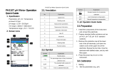
SENSOR INSTALLATION
The HI7698194 can support three different sensors:
Connector 1: pH, pH/ORP
Connector 2: D.O.
Connector 3: EC.
To make installation easier, the sensors have color‑coded caps and the sockets are identified with
colored triangles, corresponding to the colors of the sensors (pH ‑ red; EC ‑ blue; D.O. ‑ white).

20
The HI7698195 support two different sensors:
Connector 1: pH, pH/ORP
Connector 2: EC
The HI7698196 support two different sensors:
Connector 1: pH, pH/ORP
Connector 2: D.O.
SENSOR INSTALLATION
/