XG0226 - 120519
Installation & Maintenance Manual
®
C
US
WARNING:
FIRE OR EXPLOSION HAZARD
Failure to follow safety warnings exactly could result in serious injury,
death, or property damage.
—Donotstoreorusegasolineorotherammablevaporsand
liquidsinthevicinityofthisoranyotherappliance.
— WHAT TO DO IF YOU SMELL GAS
• Do not try to light any appliance.
• Do not touch any electrical switch; do not use any
phoneinyourbuilding.
• Leavethebuildingimmediately.
• Immediatelycallyourgassupplierfromaneighbour's
phone. Follow the gas supplier’s instructions.
• Ifyoucannotreachyourgassupplier,callthere
department.
—Installationandservicemustbeperformedbyaqualied
installer,serviceagencyorthegastter.
DelRay INDOOR DIRECT VENT GAS FIREPLACE
DRL3613NI 16,000 BTU/hr Natural Gas or Propane Gas
DRL3613NI-2 16,000 BTU/hr Natural Gas or Propane Gas
DRL4813NI 21,000 BTU NG /19,000 BTU Propane /hr
DRL4813NI-2 21,000 BTU NG /19,000 BTU Propane /hr
A barrier designed to reduce the risk of burns
from the hot viewing glass is provided with this
appliance and shall be installed for the protection
of children and other at-risk individuals.
HOT GLASS WILL CAUSE BURNS.
DO NOT TOUCH GLASS UNTIL
COOLED.
NEVER ALLOW CHILDREN
TO TOUCH GLASS.
DANGER
Installation and service must be performed by a qualied installer,
service agency or the gas tter. Check local codes and read all
instructions prior to installation.
Some materials used in the manufacturing process of this product can
expose you to Benzene which is known in the State of California to
cause cancer and birth defects or other reproductive harm. For more
information go to www.P65warnings.ca.gov
WARNING
Installer: Leave this manual with the appliance. Please refer to the
Montigo website for the most current version of the replace manual
Consumer: Retain this manual for future reference. Please refer to the
Montigo website for the most current version of the replace manual
NOTICE

2
General
XG0226 - 120519
Figure 1 DR and DR Builders Specications
Congratulations on your purchase of a Montigo Fireplace.
With over 30 years of experience, Montigo is committed to providing
you with a gas fireplace that is not only a beautiful addition to your
space, but that is also designed and manufactured to the highest
safety, reliability and engineering standards.
We strongly encourage you to read and carefully follow the
instructions laid out in this Installation, Operation and Maintenance
Manual and retain it for your future reference. Pay special attention
to all cautions, warnings, and notices throughout this manual
intended to ensure your safety.
This manual covers installation, operation and maintenance. Lighting,
operation and care of this replace can be easily performed by the
homeowner. All installation and service work should be performed
by a qualied or licensed installer, plumber or gas tter as certied
by the state, province, region or governing body where the replace
is being installed.
This installation, operation and maintenance manual is applicable
to the models described in Table 1. Refer to your rating plate to
verify included options.
Warranty and Installation Information: (See Appendix B)
The Montigo warranty will be voided by, and Montigo disclaims any
responsibility for, the following actions:
• Modication of the replace and/or components including Direct-
Vent assembly or glass doors.
• Use of any component part not manufactured or approved by
Montigo in combination with this Montigo replace system.
• Installation other than as instructed in this manual.
• Consult your local Gas Inspection Branch on installation
requirements for factory-built gas replaces. Installation & repairs
should be done by a qualied contractor.
Eciencylisting
MODEL
P.4. 1-15
Eciency
‡
DRL3613NI 71
DRL3613LI 71
DR3613NI-2 71
DR3613LI-2 71
DRL4813NI 63
DRL4813LI 60
DRL4813NI-2 63
DRL4813LI-2 60
BTU Listing
MODEL
Natural Gas
Liquid Propane
BTU / hr
Linear Burner w/
Glass Accessories
SIT Elect. Ignition
SIT Elect. Ignition BASIC
DRL3613NI X 16,000
X X
DRL3613LI X 16,000
X X
DR3613NI-2 X 16,000
X X
DR3613LI-2 X 16,000
X X
DRL4813NI X 21,000
X X
DRL4813LI X 19,000
X X
DRL4813NI-2 X 21,000
X X
DRL4813LI-2 X 19,000
X X
Introduction
Efficiency
Safety Alert Key
Young children should be carefully supervised when they are in the
same room as the appliance. Toddlers, young children, and others
may be susceptible to accidental contact burns. A physical barrier is
recommended if there are at-risk individuals in the house. To restrict
access to a replace or stove, install an adjustable safety gate to keep
toddlers, young children, and other at-risk individuals out of the room
and away from hot surfaces
CAUTION
Indicates a hazardous situation which, if
not avoided, WILL result in death or serious
injury or property damage.
Indicates a hazardous situation which, if not
avoided, WILL result in minor or moderate
injury.
Indicates a hazardous situation which, if not
avoided, COULD result in death or serious
injury or property damage.
Indicates practices that are important, but
not related to personal injury.
DANGER
CAUTION
WARNING
NOTICE

3
General
XG0226 - 120519
Contents
Safety Alert Key .................................................................................. 2
Introduction ....................................................................................... 2
Efficiency ............................................................................................. 2
Section A: Before You Begin .......................................................................4
Installation Checklist ......................................................................................4
Standard Installation Checklist ....................................................................5
Rating Plate Sample .......................................................................................6
Section 1: Dimensions ....................................................................... 7
DelRay Dimensions ........................................................................................7
Section 2: Framing ............................................................................ 8
In Wall and Corner Dimensions ..................................................................8
Alcove above the fireplace ...........................................................................8
Clearances ........................................................................................................9
Section 3: Venting .............................................................................. 9
Section 3-3-1: Venting Layout ......................................................... 10
Wall and Roof mounted venting ...............................................................10
Section 3-2: Installing a Roof Mounted Direct Vent Termination
for4''/7''(MVTK-1) ............................................................................ 11
Section 3-2-1: Venting Layout ...................................................................11
Section3-3:InstallingaWallMountedTermination4''/7'' ......... 12
Section 3-3-2: Venting Components ........................................................13
Section 3-3-2.2: Duravent DirectVent Pro 4” x 6⅝” Venting Compo-
nents ................................................................................................................14
Section3-3-3:HeatShields4''/7'' .................................................... 15
Section 4: Wiring .............................................................................. 16
DRL**13 (N/L) I Wiring Diagram ...............................................................16
Installation of the wall switch .....................................................................16
DR**13 (N/L) I-2 Wiring Diagram ..............................................................17
Installation of Electrical Supply .................................................................17
Section 5: Installing the gas line..................................................... 18
Fuel Type .........................................................................................................18
Gas Pressure .................................................................................................18
Section 5-3: GAS CONNECTION ................................................................ 18
Section 6: Finishing .......................................................................... 19
Finishing Around the Fireplace .................................................................19
Cement Board Install ................................................................................... 19
Section8:Removing&InstallingtheScreen/Door .................... 20
Removing the Screen...................................................................................20
Reinstalling the Screen ................................................................................20
Removing the door ......................................................................................20
Reinstalling the door ....................................................................................20
PropaneConversion ........................................................................ 21
Section 9: Installing the Accessories .............................................. 23
Installing the Fireglass or Optional Glass Media ...................................23
DelRay 36" Optional Log Kit Installation .................................................23
Propane Driftwood Layout ......................................................................... 23
Natural Gas Driftwood Layout ...................................................................23
DelRay 48" Optional Log Kit Installation .................................................24
Propane Driftwood Layout ......................................................................... 24
Natural Gas Driftwood Layout ...................................................................24
Section 10: Cleaning and Maintenance ........................................ 26
General............................................................................................................26
Cleaning ..........................................................................................................26
Pilot Burner Adjustment. ............................................................................26
Troubleshooting............................................................................................27
Direct Vent Outdoor Applications ............................................................27
Notes ...............................................................................................................27
Appendix A: Venting Terminations ................................................ 28
Appendix B: Warranty ..................................................................... 29
Appendix B: Warranty Continued .................................................. 30
Appendix C: Amendment ................................................................ 31
Thisappliancemaybeinstalledinanaftermarket,
permanently located, manufactured home (USA
only)ormobilehome,wherenotprohibitedby
local codes.
This appliance is only for use with the type of gas
indicatedontheratingplate.Aconversionkitis
supplied with the appliance.

4
General
XG0226 - 120519
IMPORTANT MESSAGE: SAVE THESE INSTRUCTIONS
The DelRay replaces must be installed in accordance with these
instructions. Carefully read all the instructions in this manual rst.
Consult the Local Gas Branch to determine the need for a permit prior
to starting the installation. It is the responsibility of the installer to
ensure this replace is installed in compliance with the manufacturers
instructions and all applicable codes.
InstallationChecklist
• Determine the desired install location of your replace.
• See Section 1, Dimensions on Page 6, and refer to the Framing
Section 2 for details.
• Select the location of your termination and resulting vent run.
• Should it be impossible to meet the venting requirements laid out
in Section 3: Venting, please contact your Montigo dealer regarding
the use of a Montigo Power Vent.
• Lay out the Vent run; calculating the required elbows and straight
runs of 4"/7" ex and/or rigid pipe.
• Layout Electrical Requirements refer to Section 4: Wiring, for Details.
• Refer to Section 5: Installing the Gas Line, for details on the gas
connection and access.
• Refer to local codes and guidelines for installation requirements.
• Installation and repairs should be done by a qualied contractor
and must conform to:
• Installations in Canada must conform to the local codes or in the
absence of local codes to the current version of Natural Gas and
Propane Installation Code, CSA B149. Electrical installations must
conform to the local codes or, in the absence of local codes, to the
current version of Canadian Electrical Code, CSA C22.1.1
• Installations in the USA must conform to the local codes or in the
absence of local codes to the current version of National Fuel Gas
Code, ANSI Z223.1/NFPA 54. Electrical installations must conform
to the local codes or, in the absence of local codes, to the current
version of the National Electrical Code, ANSI/NFPA 70. See Appendix
C for installation within the State of Massachusetts
Do not use this appliance if any part has been under water.
Immediately call a qualied service technician to inspect the appliance
and to replace any part of the control system and any gas control that
has been under water
Due to high temperatures, the appliance should be located out of
trac and away from furniture and draperies
Children and adults should be alerted to the hazards of high surface
temperature and should stay away to avoid burns or clothing ignition
A barrier designed to reduce the risk of burns from the hot viewing
glass is provided with this appliance and shall be installed for the
protection of children and other at-risk individuals
Clothing or other ammable material should not be placed on or near
the appliance
Installation and repair should be done by a qualied service person.
The appliance should be inspected before use and at least annually
by a professional service person. More frequent cleaning might be
required due to excessive lint from carpeting, bedding material, etc. It
is imperative that control compartments, burners, and circulating air
passageways of the appliance be kept clean
NOTICE
NOTICE
NOTICE
NOTICE
NOTICE
NOTICE
ThisappliancemaybeinstalledasanOEMinstallationina
manufacturedhome(USAonly)ormobilehomeandmustbe
installed in accordance with the manufacturers instructions and
the Manufactured Home Construction and Safety Standard, Title 24
CFR, Part 3280, in the United States, or the Standard for Installation in
Mobile Homes, CAN/CSA Z240 MH, in Canada.
This appliance is only for use with the type(s) of gas indicated on
theratingplate.Aconversionkitissuppliedwiththeappliance.
Section A: Before You Begin

5
General
XG0226 - 120519
StandardInstallationChecklist
This standard installation checklist is to be used by the installer in conjunction with, not instead of, the instructions contained within this
installation manual.
Customer Date Installed:
Install Address: Location of Fireplace:
Installer:
Model (circle one): DRL3613NI, DRL3613NI-2, DRL4813NI, DRL4813NI-2
DRL3613LI, DRL3613LI-2, DRL4813LI, DRL4813LI-2
Dealer Phone:
Serial #:
*Only applicable for Builders Series
YES NO IF NO, WHY NOT?
Appliance Install: Section 2
Framing complies with install manual.
Standos have been installed.
Proper clearances have been maintained.
Venting: Section 3
Venting conguration complies with vent diagrams.
Venting installed, fastened, and secured in place maintaining proper clearance.
Firestops installed.
Exterior wall/roof ashing installed and sealed in compliance with local building code.
Terminations installed and sealed in compliance with local building code.
Direct vent termination is highest point in vent assembly.
Wiring/Electrical:Section4
Unswitched power provided to the appliance PPO box.
Low voltage wire connected to dry contact wall switch (non-powered)*
Gas: Section 5
Proper appliance for fuel type.
Was a conversion performed?
Leak check performed & inlet pressure veried.
Finishing: Section 6
Only non-combustible materials installed in non-combustible areas.
Clearances meet installation manual requirements
Mantels and/or projections comply with install manual
Appliance Setup: Section 7 through 9
Media, door, and screen installed according to install manual
Manual given to home owner.
Started appliance and veried no gas leaks exist.
Comments:

6
General
XG0226 - 120519
Rating Plate Sample
Figure 1.1 Rating Plate for DelRay DRL3613NI-2 Figure 1.2 Rating Plate for DelRay DRL4813NI-2
Serial No.:
N & H ( 0 - 4500 ft. / 0 - 1371 m.)
Max. Input Min. Input Output / Orifice Size / Taille D'Orifice Gas Manifold
Max. Entrée Min. Entrée
Rendement
Front/Avant Rear/Derrière Pressure / Pression
BTU/H BTU/H BTU/H
D'Admission Du Gaz
X
16,000 16,000 N/A 49 DMS / N/A 3.5" W.C.
LBA ANSI Z21.88-2016 RV. 06-19-2019
Type: Vented Gas Fireplace Heater For Indoor Use Only
*Clearance to Combustibles
Not for use with solid fuel. / Pas pour l'usage avec le combustible solide.
*Degagements Aux Combustibles
Not for use with air filters. / Pas pour l'usage avec des filtres à air.
Sides/Côtés: 1"
Model No. Modèle.
DRL3613NI-2
Back/Derrière: 2"
Distributed by / distribué par: Canadian Heating Products Inc., Langley BC, (www.montigo.com)
Floor/Plancher: 0"
Montigo DelRay Corp., Ferndale, WA. (www.montigo.com)
X-XXXXXX-XXXXXX
Top-Top Vent/Du Haut-Évent Du Haut: 21"
Top-Rear Vent/Du Haut-Évent Arrière: N/A
Mantel/Manteau: 6"
Tested To / Examiné À: ANSI Z21.88-2016 / CSA2.33-2016
Recess Depth/ Profondeur D'Encadrement:
N/A
Electrical Rating / Estimation Électrique:115V / 1Ph / 60Hz /less than 12A
Facing: NC
Altitude Rating / Estimation D'Altitude:
Fuel Type / Type De Carburant:
Min. Gas Supply
Pressure/ Min. Pression
Do Not Remove
This Label
D'Alimentation Du Gaz
Natural Gas / Gaz Naturel
5.5" W.C.
Made in China
Fabriqué en Chine
16,000 16,000 N/A 1.15 mm / N/A 10" W.C. 13" W.C.
N'enlevez Pas Cette
Étiquette
Propane / Gaz Propane
FOR USE WITH GLASS DOORS AND SCREENS CERTIFIED WITH THE APPLIANCE ONLY
Pour utilisation avec portes de verre and écrans de certifiés avec l'appareil seulement
*Refer to installation manual for more information.
*Référez-vous au manuel d'installation pour plus d'information.
Serial No.:
N & H ( 0 - 4500 ft. / 0 - 1371 m.)
Max. Input Min. Input Output / Orifice Size / Taille D'Orifice Gas Manifold
Max. Entrée Min. Entrée
Rendement
Front/Avant Rear/Derrière Pressure / Pression
BTU/H BTU/H BTU/H
D'Admission Du Gaz
X
21,000 21,000 N/A 2.15 mm / N/A 3.5" W.C.
LBA ANSI Z21.88-2016 RV. 06-19-2019
N'enlevez Pas Cette
Étiquette
Propane / Gaz Propane
FOR USE WITH GLASS DOORS AND SCREENS CERTIFIED WITH THE APPLIANCE ONLY
Pour utilisation avec portes de verre and écrans de certifiés avec l'appareil seulement
*Refer to installation manual for more information.
*Référez-vous au manuel d'installation pour plus d'information.
Made in China
Fabriqué en Chine
19,000 19,000 N/A 1.3 mm / N/A 10" W.C. 13" W.C.
Fuel Type / Type De Carburant:
Min. Gas Supply
Pressure/ Min. Pression
Do Not Remove
This Label
D'Alimentation Du Gaz
Natural Gas / Gaz Naturel
5.5" W.C.
Mantel/Manteau: 6"
Tested To / Examiné À: ANSI Z21.88-2016 / CSA2.33-2016
Recess Depth/ Profondeur D'Encadrement:
N/A
Electrical Rating / Estimation Électrique:115V / 1Ph / 60Hz /less than 12A
Facing: NC
Altitude Rating / Estimation D'Altitude:
X-XXXXXX-XXXXXX
Top-Top Vent/Du Haut-Évent Du Haut: 21"
Top-Rear Vent/Du Haut-Évent Arrière: N/A
Distributed by / distribué par: Canadian Heating Products Inc., Langley BC, (www.montigo.com)
Floor/Plancher: 0"
Montigo DelRay Corp., Ferndale, WA. (www.montigo.com)
Not for use with air filters. / Pas pour l'usage avec des filtres à air.
Sides/Côtés: 1"
Model No. Modèle.
DRL4813NI-2
Back/Derrière: 2"
Type: Vented Gas Fireplace Heater For Indoor Use Only
*Clearance to Combustibles
Not for use with solid fuel. / Pas pour l'usage avec le combustible solide.
*Degagements Aux Combustibles

7
Installation
XG0226 - 120519
41
3/8”
38
3/8”
45
1/4”
3
1/8”
12
5/16”
12
3/4”
24
1/2”
26
3/4”
16
5/8”
6
9/16”
14
11/16”
36
1/2”
4”
5”
7”
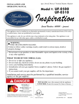
DelRay Dimensions
Section 1: Dimensions
Figure 2. DelRay Fireplace dimensions (Tolerance ± ⅛").
DRL*3613 DIMENSIONS
A B C D
41⁄ 38⁄ 36½ 45¼
DRL*4813 DIMENSIONS
A B C D
53⁄ 50⁄ 48½ 57¼
A
B
C
D

8
Installation
XG0226 - 120519
Section 2: Framing
1). Frame in the enclosure for the unit with framing materials. The
framed opening for the assembled replace shown below in table
NOTE: When constructing the framed opening, please ensure there is
access to install the gas line when the unit is installed
* When sheetrock is used behind the replace, framing depth may be
increased by 1/2".
Clearances must be in accordance with local installation codes and
the requirements of the gas supplier
Figure 3.b Framing dimensions (Straight wall & Corner Installation).
Figure 3.a Framing dimensions table
NOTICE
When this appliance is installed directly on ANY combustible other
than wood ooring (carpet, vinyl, etc.). It must be installed on an
equivalent wood or metal panel. This material must extend the full
width and depth of the appliance.
WARNING
In Wall and Corner Dimensions Alcoveabovethefireplace
Figure 3.d Non-combustible Framing for shelves over the replace
1" Min.
Non-combustible
materials.Alcove
overreplace
CeilingLevel
10"
12"
Door
Opening
Floor
Non-Combustible
header
362
14
1
4
"
1101.100
43
3
8
"
856
33
11
16
"
1:32
DWG. NO.
SHEET 1 OF 3
WEIGHT:
MNR36 Framing Assembly
Finish
MATERIAL
Revision / Date
Drawn by
DATE
NAME
31/07/2018
THE INFORMATION CONTAINED IN THIS DRAWING IS THE SOLE PROPERTY OF CANADIAN HEATING PRODUCTS. ANY REPRODUCTION IN PART OR AS A WHOLE WITHOUT THE WRITTEN PERMISSION OF CANADIAN HEATING PRODUCTS IS PROHIBITED.
PROPRIETARY AND CONFIDENTIAL
Y:\Products\Residential Products\R&D Projects\MNR36\CAD Drawings\MNR36 Framing Assembly
March-14-19 11:00:17 AM
SCALE
DM
Description
MNR36 Framing Assembly
Revision
DIMENSIONS ARE IN INCHES
TOLERANCES:
FRACTIONAL
1/32"
TWO PLACE DECIMAL
.015"
THREE PLACE DECIMAL
.005"
ANGULAR
.5
ALL BENDS ARE ASSUMED
TO BE 90
UNLESS NOTED
OTHERWISE.
12.700
1
2
"
12.700
1
2
"
1206
47
1
2
"
1705
67
1
8
"
1101.100
43
3
8
"
1:32
DWG. NO.
SHEET 3 OF 3
WEIGHT:
MNR36 Framing Assembly
Finish
MATERIAL
DIMENSIONS ARE IN INCHES
TOLERANCES:
FRACTIONAL
1/32"
TWO PLACE DECIMAL
.015"
THREE PLACE DECIMAL
.005"
ALL BENDS ARE ASSUMED
TO BE 90
UNLESS NOTED
OTHERWISE.
Revision / Date
Drawn by
DATE
NAME
15/08/2018
THE INFORMATION CONTAINED IN THIS DRAWING IS THE SOLE PROPERTY OF CANADIAN HEATING PRODUCTS. ANY REPRODUCTION IN PART OR AS A WHOLE WITHOUT THE WRITTEN PERMISSION OF CANADIAN HEATING PRODUCTS IS PROHIBITED.
PROPRIETARY AND CONFIDENTIAL
Y:\Products\Residential Products\R&D Projects\MNR36\CAD Drawings\MNR36 Framing Corner Assembly
March-14-19 11:02:44 AM
SCALE
DM
Description
MNR36 Freaming Corner Assembly
Revision
Framing header must
beturnedonedgeto
meetventclearance
DRL*3613 DIMENSIONS
A B C
43⁄ 67⁄ 47½
DRL*4813 DIMENSIONS
A B C
55⁄ 79¼ 56⁄
A
34"
A
B
C

9
Installation
XG0226 - 120519
Clearances
MODEL
Top - Top
vent†
Rear
Sides
Floor
Mantel
Vent Pipe
DRL**3613*I 21" 2" 1" 0" 6"
1'' all around
2" on the
horizontal
DRL**4813*I 21" 2" 1" 0" 6"
1'' all around
2" on the
horizontal
NOTES:
† Clearance from top of replace to a ceiling within the replace
enclosure.
Figure 4. Combustible Wall Clearances
When installing a shelf over the top of the replaces, the following
guidelines must be adhered to:
Section 3: Venting
Montigo oers a variety of direct venting and termination options. The
direct vent termination location MUST be selected such that it is the
highest point in the venting assembly. It should also be selected such
that it provides the shortest vent run possible. Should it be impossible
to ensure that the termination is the highest point or to meet the
venting guidelines laid out below please contact your Montigo dealer
to discuss power venting options.
Notes For Planning Venting:
• Venting originates from the top of the unit
• Venting can terminate through the roof or through an exterior wall.
• Refer to Appendix A - Termination Locations to ensure the planned
termination location is acceptable.
• Once the termination location has been established, refer to the
appropriate section below for installation details
• All replaces shipped from the factory are top vent.
• Silicone application is NOT required when joining Montigo vent
pipes and components.
Under no circumstances can Montigo ex venting be cut to
accommodate an installation. Use an alternative length to complete
your vent run. (Excluding ex included in the MVK05)
NOTICE
MFVK05
MFVK05 Flex Vent Kit is a standalone 5 ft. vent kit that cannot
be combined with Montigo Flex or Montigo Rigid pipe to extend
beyond the 5ft of ex included in this kit. The Flex in this kit
can be cut down if shortening is required. Any other venting
conguration beyond the 5ft included in the MVK05 kit will
require going to either Montigo Rigid pipe or Montigo Flex pipe
referenced in the manual pages Venting section.
Figure 4.a MFVK05 Flex Vent Kit

10
Installation
XG0226 - 120519
13"
MIN.
DELRAY
UNIT
MTO-4F
OUTDOOR
WALL
FLEX
PIPE
FLOOR
1:32
DWG. NO.
SHEET 1 OF 2
WEIGHT:
MNR36 Complete Assembly
Finish
MATERIAL
Revision / Date
Drawn by
DATE
NAME
26/09/2018
THE INFORMATION CONTAINED IN THIS DRAWING IS THE SOLE PROPERTY OF CANADIAN HEATING PRODUCTS. ANY REPRODUCTION IN PART OR AS A WHOLE WITHOUT THE WRITTEN PERMISSION OF CANADIAN HEATING PRODUCTS IS PROHIBITED.
PROPRIETARY AND CONFIDENTIAL
Y:\Products\Residential Products\R&D Projects\MNR36\CAD Drawings\MNR36 Complete Assembly
December-18-18 1:38:11 PM
SCALE
DM
Description
DelRay - Venting Assembly.
Revision
DIMENSIONS ARE IN INCHES
TOLERANCES:
FRACTIONAL
1/32"
TWO PLACE DECIMAL
.015"
THREE PLACE DECIMAL
.005"
ANGULAR
.5
ALL BENDS ARE ASSUMED
TO BE 90
UNLESS NOTED
OTHERWISE.
Figure 4.bb Minimum Horizontal vent run (Flex)
Figure 4.bb Minimum Horizontal vent run (Rigid)
VERTICAL TABLE
Horizontal
Maximum
H1+H2
10'
20'
Vertical
Minimum
V1+V2+V3
4'
8'
HORIZONTAL TABLE
Horizontal
Maximum
H1+H2+H3
10'
20'
Vertical
Minimum
V1+V2
4'
8'
WallandRoofmountedventing
34'MAXIMUMVERTICALHEIGHT
20'MAXIMUMHORIZONTALOFFSETS
4 MAXIMUM 90° ELBOWS PERMITTED
The minimum vent system for horizontal termination must consist of:
13" to vent center, then straight out the wall (using ex kit)
The maximum vent system consists of:
34’ vertical length with 4 - 90° bends and a 20’ horizontal length
(measured to center of pipe)
Maximum Vertical vent run:
34’ vertical length with a roof termination,
restrictor recommended.
Maximum Horizontal vent run:
34’ vertical length with 4 elbows, and
the maximum 20 feet horizontal run.
16
1
8
"
MIN.
OUTDOOR
WALL
MTO-4F
DELRAY
UNIT
FLOOR
REVISIONS
REV.
DESCRIPTION
DATE
CHANGED BY
-
.
- -
1:24
DWG. NO.
SHEET 2 OF 2
WEIGHT:
Finish
MATERIAL
DIMENSIONS ARE IN INCHES
TOLERANCES:
FRACTIONAL
1/32"
TWO PLACE DECIMAL
.015"
THREE PLACE DECIMAL
.005"
ANGULAR
.5
ALL BENDS ARE ASSUMED
TO BE 90
UNLESS NOTED
OTHERWISE.
Revision / Date
Drawn by
DATE
NAME
26/09/2018
THE INFORMATION CONTAINED IN THIS DRAWING IS THE SOLE PROPERTY OF CANADIAN HEATING PRODUCTS. ANY REPRODUCTION IN PART OR AS A WHOLE WITHOUT THE WRITTEN PERMISSION OF CANADIAN HEATING PRODUCTS IS PROHIBITED.
PROPRIETARY AND CONFIDENTIAL
Y:\Products\Residential Products\R&D Projects\MNR36\CAD Drawings\MNR36 Complete Assembly
December-18-18 1:38:11 PM
SCALE
DM
Description
DelRay - Venting Assembly.
Revision
MNR36 Complete Assembly
H1
H1
H2
H3
H2
V2
V2
V3
V1
V1
37 1/2'' Min. 40.652'' Min.
Section 3-3-1: Venting Layout

11
Installation
XG0226 - 120519
Roof mounted terminations
The following details are some possible congurations for roof mounted
terminations. See below.
This section applies to installations where the direct vent termination
will be roof mounted.
Section 3-2-1: Venting Layout
Selection of components and details of venting lay out should adhere
to the following guidelines:
• The maximum termination point is 34’ above the replace (NOTE:
if the maximum termination height is used, the ame pattern may
be aected).
• The Vertical termination must be a minimum 2’ higher than where
the termination exits the roong materials, (asphalt shingles, cedar
shakes, etc). This distance should be measured from the high side of
the roof slope where the ue ashing intersects the roong materials.
• Termination location must be a minimum 6’ from a mechanical air inlet.
• For a more detailed diagram of allowed termination locations, see
Appendix A.
• A maximum of two osets (each oset is made up of 2-90° bends) may
be made for vertical vent runs. (2 45° bends are equivalent to 1 90°)
• Firestops must be installed as required by National & local codes.
• Ensure all horizontal runs are supported with a minimum of 3
supports per 10’ of venting.
• Install all roof ashing and storm collars as shown.
Figure 6. Top vent, roof mounted termination with no oset in vent run.
Figure 6.b Top vent, roof mounted with 1 oset (1 oset= two 90° bends).
Section 3-2: Installing a Roof Mounted Direct Vent
Terminationfor4''/7''(MVTK-1)
MVTK1 Termination
MVTK1 Termination
MVTK1 Termination
Storm collar
Storm collar
Storm collar
2' min
2' min
2' min
Support ring
Support ring
Support straps OR
Support ring and
plates
Support ring and
plates
Support plate
Support plate
Firestop
Firestop
Obstacle
Obstacle
Firestop
34' max
34' max
Roof ashing
Roof ashing
Roof ashing
Figure 6.c Top vent, roof mounted with 2 osets (1 oset= two 90° bends).
Firestop
34' max
Firestop

12
Installation
XG0226 - 120519
Figure 7. Installing a MTO4-F termination.
Figure 7.b Installing a PTO termination with the MSR frame.
Figure 7.c Installing a MTO termination with the BSR frame.
Figure 7.d Installing a MTO termination with MOSR frame.
Figure 7.e Installing the VSS Vinyl Shield.
Figure 7.f Installing a MTO termination heat guard.
1
12”
2”
1
2”
12”
This section applies to installations where the direct vent termination
will be wall mounted. NOTE: If subject to a highly corrosive environment
i.e. Seaside, Montigo recommends using Stainless Steel Termination.
Section3-3:InstallingaWallMountedTermination4''/7''
Installationofterminationwithbuiltinframe
A termination with a built-in frame is installed during framing of a
structure.
1. Frame the termination opening to 11" x 11".
2. Install exterior sheathing to the structure framing.
3. Fasten the termination to the sheathing using a minimum of 4 screws.
MSR Frame
MTO-4 (4"/7")
Termination
MTO-4F (4"/7")
Termination
Installationofaterminationshieldforvinylsiding
The VSS Termination shield is installed when the exterior of a structure
is clad with Vinyl siding. It is placed directly above, and on-center with
the termination.
Installation of termination frame at time of framing
Terminations with a MSR frame allow the installation of the frame prior
to installation of the termination.
1. Frame the termination opening to 12" x 12".
2. Secure the MSR Frame to the exterior sheathing of the structure.
3. Fasten the termination to the MSR Frame using a minimum of 4 screws.
1. Frame the MOSR opening to 12" x 12".
2. Fasten the MOSR frame to the interior side of the studs, concrete,
or nished wall construction using a minimum of 4 screws.
3. Insert the termination into the MOSR frame as shown here, (from
the inside) and attach to the MOSR by installing a min. quantity of 4
bolts into the threaded nuts on the MOSR Frame.
Installation of termination frame at time of framing in masonry
Terminations with a BSR frame allow the installation of the frame in
masonry prior to the installation of the termination
1. Frame the BSR opening to 12" x 12".
2. Secure the BSR Frame to the exterior sheathing of the structure.
3. Fasten the termination to the BSR Frame using a minimum of 4 screws.
BSR Frame
MTKOG 4"/7")
Installing heat guards
Installing heat guards over terminations is recommended in installations
where the termination is located within 7' feet above grade, or above
a pedestrian walkway, and may be required by code in public areas.
1. Ensure that the two long mounting brackets are facing the bottom
of the termination (See inset). This will provide more heat protection
at the top of the termination, where temperatures are highest.
2. Attach to the faceplate of the termination using four sheet metal
screws.
1
1”
11”
Framing
Exterior
Sheathing
Fastening Hard-
ware, minimum
4-screws
Framing
Exterior
Sheathing
Fastening Hardware,
minimum 4-screws
MTO-4 (4"/7")
Termination
Framing
Exterior
Sheathing
Fastening Hardware,
minimum 4-screws
Exterior Vinyl
siding
MTO-4 (4"/7")
Termination
VSS Vinyl shield
Installation of termination from inside structure
A Termination with a MOSR Frame is installed from the inside of the
structure. These are commonly used in high-rise construction.
MOSR Frame
MTO-4 (4"/7")
Termination
12”
12”
Fastening Hardware,
minimum 4-screws
Framing,
concrete
or other
materials
Exterior
Sheathing, concrete
or other materials

13
Installation
XG0226 - 120519
Connectionandinstallationofthevent
components should adhere to the following
guidelines:
Section 3-3-2: Venting Components
The following components and associated Montigo part numbers are for
installation of a roof or wall mounted termination. Use of non-Montigo
approved parts will VOID the warranty and may impede operation of
the replace.
• Use any combination of rigid and ex pipe as required and in any
orientation (Male connectors can face in any direction).
• Flex sections may be stretched up to 50% of their total length (e.g.
a 24” section maybe stretched to 36”).
• Connect all vent sections using a minimum of three sheet metal
screws on the outer pipe ue.
• Ensure the pipe ends male to female slide in a minimum of 1 1/2”
of overlap.
• Ensure all horizontal runs are supported with a minimum of 3
supports per 10’ of venting.
• When hanging/supporting venting, ensure that 1” clearance is
maintained on sides and bottom of vent runs and 2” above horizontal
vent runs to any combustible material.
• Rigid pipe may be cut less than half way from the FEMALE END ONLY.
• Ensure when cutting sections of rigid pipe to maintain integrity of
internal supports.
• Flex pipe cannot be cut
• Place the springs, supplied with the pipe kit (ex only), between the
outer and inner pipes to keep the pipes separate and avoid any
possible hot spots.
• Montigo recommends the use of a ex section for the rst section of
venting connected directly to the replace, oering greater exibility
of installation and absorption of movement.
• Firestops must be installed as required by national & local codes.
• Montigo recommends that all exterior corners and joints be sealed
with exterior caulking. However, we encourage you to consult your
Building Envelope Engineer or Waterproong Consultant for further
recommendations.
IMPORTANT:
Please refer to your Building Envelope Engineer
or Waterproong Consultant for a review of ALL
penetrations through exterior walls or the roof.
A - Termination MTO4 (3" Length)
MTO4F (3" Length)
MTO4FSS
B - Frame Kits MSR (Stucco Frame)
MOSR (Stucco Frame)
BSR-4 (4" Brick Frame)
BSR-6 (6" Brick Frame)
C - Flex Sections MFL - 1 (12" f/f Section)
MFL - 18 (18" f/f Section)
MFL - 2 (24" f/f Section)
MFL - 3 (36" f/f Section)
MFL - 4 (48" f/f Section)
MFL - 6 (72" f/f Section)
D - Rigid Pipe MEXT - 1 (12" f/m Section)
MEXT - 2 (24" f/m Section)
MEXT - 3 (36" f/m Section)
MEXT - 4 (48" f/m Section)
MEXT - 6 (72" f/m Section)
E - Rigid Pipe Extension EXT18 (18" f/f Section)
F-Elbows MEL-90MM (m/m 90º Elbow)
MEL-90FF ( f/f 90º Elbow)
MEL-90FM ( f/m 90º Elbow)
MEL-45FM ( f/m 45º Elbow)
G - Wall Penetration Kit MFVK01F
H-SupportRing&Plate MSPXT7
I - Firestop FS7
J - Roof Flashing MRF7 (1/12 - 7/12 pt.)
MRF12 (7/12 - 12/12 pt.)
K - Heat Shield RHS100
L - Heat Guard MTKOG

14
Installation
XG0226 - 120519
46DVA-AD-M2 Termination
Adapter
46DVA-AD-M1 Mounting
Adapter
Section3-3-2.2:DuraventDirectVentPro4”x6⅝”VentingComponents
The following Simpson Duravent venting components are approved for use with Montigo products. Please
contact your local Montigo dealer for further information.
Component MontigoPartNumber SimpsonDuraventPartNumber
A - Termination MTO4 (3" Length)
MTO4F (3" Length)
MTO4FSS
Must use Montigo termination
B - Frame Kits MSR (Stucco Frame)
MOSR (Stucco Frame)
BSR-4 (4" Brick Frame)
BSR-6 (6" Brick Frame)
Must use Montigo termination
C - Flex Sections MFL - 1 (12" f/f Connectors)
MFL - 18 (18" f/f Section)
MFL - 2 (24" f/f Section)
MFL - 3 (36" f/f Section)
MFL - 4 (48" f/f Section)
MFL - 6 (72" f/f Section)
46DVA-48FF (48" F/F Section)
46DVA-120FF (120"f/f Section)
D - Rigid Pipe
MEXT - 1 (12" f/m Section)
MEXT - 2 (24" f/m Section)
MEXT - 3 (36" f/m Section)
MEXT - 4 (48" f/m Section)
MEXT - 6 (72" f/m Section)
46DVA-06 (6" Section)
46DVA-09 (9" Section)
46DVA-12 (12" Section)
46DVA-18 (18" Section)
46DVA-24 (24" Section)
46DVA-36 (36" Section)
46DVA-48 (48" Section)
46DVA-60 (60" Section)
E - Rigid Pipe Extension EXT18 (18" f/f Section) 46DVA-08A (8½" Length)
46DVA-16A (16" Length)
F-Elbows MEL-90MM (m/m 90º Elbow)
MEL-90FF ( f/f 90º Elbow)
MEL-90FM ( f/m 90º Elbow)
MEL-45FM ( f/m 45º Elbow)
46DVA-E30 (30° Elbow)
46DVA-E45 (45° Elbow)
46DVA-E60 (60° Elbow)
46DVA-E90 (90° Elbow)
G - Wall Penetration Kit MFVK01F
H-SupportRing&Plate MSPXT7 46DVA-ES (Elbow strap)
46DVA-RS (Roof support)
I - Firestop FS7 46DVA-WFS
46DVA-WFS2
J - Roof Flashing MRF7 (1/12 - 7/12 pt.)
MRF12 (7/12 - 12/12 pt.)
46DVA-F6(DS) (0/12-6/12 pt.)
46DVA-F12(DS) (6/12-12/12 pt.)
46DVA-FF (Flat Roof Flashing)
K - Heat Shield RHS100 46DVA-WT
46DVA-WTS
L - Heat Guard MTKOG
DirectVent Pro 4” x 6⅝” requires the 46DVA-AD-M1 Mounting
Adapter to reduce from native 4"/7" size. A Montigo 4"/7"
termination must be used by installing the 46DVA-AD-M2
Termination Adapter
NOTICE

15
Installation
XG0226 - 120519
Installing a Wall Mounted RHS7 heat shield
The RHS7 Heat shield CANNOT be used WITHIN 36" horizontal or 60"
vertically of the replace. For applications within these dimensions the
RHS100 Heat Shield MUST be used.
To install the RHS7, frame an opening in combustible construction,
Figure 15.a below. Slide the Heat shield in place over the vent pipe
which attaches to the replace. After the replace and vent pipe has
been installed, clearances should match the dimensions in Figure 15.a
Installing a Wall Mounted RHS100 Heat shield
The RHS100 Heat shield MUST be used where the RHS7 Termination
CANNOT be used. Use the RHS100 within 36" horizontal or 60" vertical.
To install the RHS100, Slide the Inner Section over the vent pipe that
will connect to the replace. Fasten the vent pipe to the back of the
replace with a Min. of three sheet metal screws.
Next, slide the RHS100 outer section from the outside of the structure.
To complete the installation fasten the Heat Shield Outer Section &
Termination frame to the structure.
Figure 15.e RHS100 Installation
Figure 15.c RHS100 Installation. (Install by sliding Outer Section over vent pipe where it passes
through the combustible construction.
Figure 15.a RHS7 Installation. (Install by sliding over vent pipe where it passes through the
combustible construction).
Figure 15.b RHS7 Installation. (Minimum requirements).
Figure 15.d Heat Shield. After sliding the outer section in place.
RHS8 Heat
Shield
36” Min
60” Min.
PTO Termination
RHS8 Heat Shield
1” Min. Both sides Typical
1” Min.
1” Min.
Combustible Framing
Section3-3-3:HeatShields4''/7''
3/8'' min. Both sides Typical
Drywall / sheetrock
Drywall / sheetrock
RHS100 Heat Shield, inner Section
RHS100 Heat Shield, inner Section
Vent pipe, from replace
Vent pipe, from replace
Combustible framing
RHS100 Heat Shield Outer Section
RHS100 Heat Shield Outer Section
Termination
Termination
3/8'' min.
1'' min.
1'' min.
3/8'' min.
Inner shield
Outer shield
Combustible Framing
1'' min. Both sides Typical
RHS7 Heat Shield
RHS7
Heat Shield
MTO Termination
37 1/2'' Min.
Combustible framing

16
Installation
XG0226 - 120519
Installation of the wall switch
Montigo supplies 15' of low voltage wire to be plugged into the control
board. Connect to a standard single pole ON/OFF switch to the location
of your choice. You may extend these wires up to 30' in length with a
wire of equal quality.
Installations in Canada must be electrically grounded in accordance
with CSA C22.1 Canadian Electrical Code Part 1 and/or Local Codes.
Installations in the USA must be electrically grounded in accordance
with local codes or, in the absence of local codes, with the National
Electrical Code, ANSI/NFPA 70.
Optional remote control available through your Montigo Dealer.
DRL**13(N/L)IWiringDiagram
BLACK
WHITE
GREEN
To PPO
SPARK
SENSOR
TO ON/OFF
WALL SWITCH
YELLOW/GREEN
ORANGE
GREEN
6
10
OPTIONAL CPI/IPI SWITCH
BLUE
WHITE
X1
X5
X4
X3
X2
3.15A FUSE
BLUE
RE
Figure 15. Wiring diagram for DRL3613NI with SIT Proame Electronic Ignition
Section 4: Wiring
MODEL
DRL3613*I
DRL4813*I
Main Power
120VAC 60Hz
6 amps

17
Installation
XG0226 - 120519
1.5V AA type
1.5V AA type
1.5V AA type
1.5V AA type
Installation of Electrical Supply
Installations in Canada must be electrically grounded in accordance
with CSA C22.1 Canadian Electrical Code Part 1 and/or Local Codes.
Installations in the USA must be grounded in accordance with local
codes or, in the absence of local codes, with the National Electrical
Code, ANSI/NFPA 70.
NOTE: If any of the original wire supplied with the appliance is replaced,
it must be replaced with the same type, or its equivalent.
Figure 17. Wiring diagram for DRL3613NI-2 with SIT Proame Electronic Ignition
MODEL
DRL3613*I-2
DRL4813*I-2
DRL**13(N/L)I-2WiringDiagram
VARIABLE SPEED
COMFORT FANS
HALOGEN LIGHTS
BLACK
RED
110V BV
TRANSFORMER
LED LIGHTS
LED1 - RED LED
LED2 AMBER LED
MAIN Power
120vac 60 hz
6 amps
3.15A FUSE
WHITE
RED
SPARK
SENSOR
YELLOW/GREEN
ORANGE
PILOT
BURNER
GREEN
885 PROFLAME
MAIN ON/OFF
SWITCH
BLACK
RED
1.5V AA TYPE
1.5V AA TYPE
1.5V AA TYPE
1.5V AA TYPE
BATTERY PACK
BLACK
WHITE
GREEN

18
Installation
XG0226 - 120519
1"
screw
safe
zone
1"
screw
safe
zone
NO SCREWS PERMITTED IN THIS
AREA. A HIGH TEMPERATURE
(140°F) DRYWALL ADHESIVE MAY
BE USED
DRYWALL (NOT INCLUDED)
Finishing Safety Zone
Take special care when nishing underneath the replace door due to
the location of the gas valve and control board. Any screw can possibly
puncture one of these components resulting in either a non operational
unit or worse, a gas leak.
Not following the safe screw area may result in puncture of the
control board or the gas valve/line.
WARNING
Fuel Type
• Verify that your replace is compatible with your available gas type.
(Natural Gas or Propane shown by "N" or "L" in your model number
• If gas type is not compatible, contact your local Montigo dealer.
Gas Pressure
• Optimum appliance performance requires proper input pressures.
• Gas line sizing requirements will be determined in ANSI Z223.1/ NFPA
54 National Fuel Gas Code in the USA and CAN/CGA B149.1 in Canada.
Pressure requirements (during operation):
• The manifold outlet pressure is set from the factory to the appropriate
pressure but should be veried.
• To check pressures, control valves have a provision to remove a 1/8”
N.P.T. plug to be tted with a hose barb.
• Montigo requires a service shut o valve be located in an accessible
location to isolate the gas supply.
• Only install gas shut-o valves approved for use by the state, province,
or other governing body in which the replace is being installed.
Section 5-3: GAS CONNECTION
• See Figure 20.b or 20.c for location of gas line access.
• Flexible gas connectors must not exceed 2 feet in length, unless
allowable within local regulations.
• Connect incoming gas line to the 1/2"or 3/8" gas inlet port.
• Check appliance connection, valve and valve train under normal
operating pressure with a commercially available leak check solution.
DO NOT USE A FLAME OF ANY KIND TO TEST FOR LEAKS.
PRESSURE REQUIREMENTS
Gas Pressure Natural Gas Propane
Minimum inlet pressure 5.5in. w.c. 13in. w.c.
Manifold pressure 3.5in. w.c. 10in. w.c.
Section 5: Installing the gas line
After gas line is connected, each appliance connection, valve and
valve train MUST be checked while under normal operating pressure
with either a Liquid Solution, or Leak Detection Device, to locate any
source of leak. Tighten any areas where bubbling appears or a leak is
detected until bubbling stops completely or leak is no longer detected.
DO NOT use a ame of any kind to test for leaks. A re or explosion
will occur, causing serious injury, property damage or death.
An inspection of the explosion relief appers and door MUST be made
prior to lighting the replace. A faulty seal on the door gasket and/or
explosion ports will result in products of combustion leaking into the
living space and may result in carbon monoxide poisoning.
WARNING
DANGER
When pressure testing the replace, gas line, and input system
follow the appropriate local codes for your area. DO NOT connect
the replace to pressures in excess of 0.5 psig. (14" w.c.) This will
damage the gas control valve.
Figure 20. Pressure Requirements
NOTICE

19
Installation
XG0226 - 120519
Section 6: Finishing
Fireplaces cannot be recessed into a wall cavity.
WARNING
We recommend careful consideration be given to the eects of
elevated mantel temperatures which may be in excess of product
design, for example: candles, plastic or pictures. This can cause
melting, deformation, discoloration or premature failure of T.V. radio,
and other electronic components.
Finishing Around the Fireplace
Mantel Projections
When sizing the nish material for your replace, it is important to
remember the following: THE OPENING MUST NOT BE OBSTRUCTED IN
ANY WAY - to do so restricts the air supply for the control compartments
and heat exchanger it also prevents access for servicing controls.
CAUTION
Cut standard Gyproc / Drywall board to complete the installation of
the surround. Fit the edge of the board to the rim around the replace
opening. Fasten the board in place using standard drywall screws.
SINGLE SIDED
Top (Qty 1)
Sides (Qty 2)
Figure 28. Supplied non-combustible cement board dimensions
Cement Board Install
Install the supplied non-combustible cement board to overlap
the new horizontal & vertical 2 x 4's, place the non-combustible
wall board above the fireplace throat, allowing 1/8" clearance
from the rim above the fireplace opening. Pre-drill the board with
1/8" drill bit and secure to framing with nails, use flat head sheet
metal screws to fasten the board to the metal header.
977
38
7
16
"
305
12"
101
4"
728
28
11
16
"
101
4"
1
2
2
REVISIONS
REV.
DESCRIPTION
DATE
CHANGED BY
B
CHANGED COMPONENTS.
12/10/2018
DM
ITEM NO.
PART NUMBER
DESCRIPTION
MATERIAL
QTY.
1
CBMNR36T
Top Cement
Board
1/2" Firepro
Wallboard
1
2
CBMNR36S
Side Cement
Board
1/2" Firepro
Wallboard
2
1:8
DWG. NO.
SHEET 1 OF 1
WEIGHT:
MNR36 Cement Board Assembly
Finish
MATERIAL
DIMENSIONS ARE IN INCHES
TOLERANCES:
FRACTIONAL
1/32"
TWO PLACE DECIMAL
.015"
THREE PLACE DECIMAL
.005"
ANGULAR
.5
ALL BENDS ARE ASSUMED
TO BE 90
UNLESS NOTED
OTHERWISE.
Revision / Date
Drawn by
DATE
NAME
28/08/2018
THE INFORMATION CONTAINED IN THIS DRAWING IS THE SOLE PROPERTY OF CANADIAN HEATING PRODUCTS. ANY REPRODUCTION IN PART OR AS A WHOLE WITHOUT THE WRITTEN PERMISSION OF CANADIAN HEATING PRODUCTS IS PROHIBITED.
PROPRIETARY AND CONFIDENTIAL
Y:\Products\Residential Products\R&D Projects\MNR36\CAD Drawings\MNR36 Cement Board Assembly
October-12-18 2:06:36 PM
SCALE
DM
Description
MNR36 Cement Board Assembly
B
Revision
DRL**3613 DIMENSIONS
A B C
38⁄ 12 28⁄
DRL**4813 DIMENSIONS
A B C
50⁄ 12 28⁄
A
B
C
Figure 19.c Sidewall clearances
Edge of door frame Sidewall
TOP OF UNIT
Sidewall clearances
Side wall clearances are 4". Combustible surrounds may be installed
with 4" clearance to the side of the replace as shown.
4" clearance in sidewall drawing does not apply to recession, unit
cannot be recessed into a wall.
NOTICE
4"
Min.
Combustible Mantle
Height 6"
Combustible Mantle
Depth 11"
Figure 19. Combustible mantles and facings. (Not to scale)
1234567891011121314
1
18
5
22
11
15
2
19
6
23
12
16
3
20
9
7
24
13
17
4
21
10
8
14
Vertical Height (In.)
Mantle width (In.)
Concrete board
Drywall
Drywall
Combustible
mantle allowed
Top of replace opening
1/8" Gap

20
Installation
XG0226 - 120519
RemovingtheScreen
Follow the steps below to remove, or install the replace screen and
door.
Before beginning any screen or glass removal, make sure that the
unit has not been in operation and that it is at room temperature.
Step 1: Locate the three tabs at the base of the screen.
Step 2: Lift out the Retaining Tabs and screen.
Pull the bottom of the screen outward, then slide out the screen from
the frame.
Store in a safe place. The Screen is very fragile and can be easily torn,
dented or deformed. Refer to Figure 20.b below.
Reinstalling the Screen
Follow the two previous steps to re-install the replace window.
Section8:Removing&InstallingtheScreen/Door
Any safety screen, guard, or barrier removed for servicing an
appliance, must be replaced prior to operating the appliance
Figure 20. Locate the three tabs at the base of the screen
Figure 20.b Lift out the Retaining Tabs and screen
NOTICE
STEP 1:
Remove lower valve blinds and screen setting bar.
STEP 1:
Line up the notch of
the bottom of the door
with the tab on the door
channel.
STEP 2:
Ensure the tool is rmly
in the lower end of the
slot, (as shown), Then
pull toward you, door will
unlatch, repeat for other
buckles.
STEP 2:
Buckles are locked into
place by pulling out and
up, latch will pop into
place.
STEP 3:
Pull the top of the door
towards you, then lift the
door up and out of the
replace frame.
Store in a safe place.
Removingthedoor
The door is removed in a few simple steps. Follow these steps below
to unlatch the door buckles and remove the door.
Reinstalling the door
NOTE: Make sure the top and base of the door slips into the narrow
channel in the frame to ensure proper placement.
Figure 21.b Installing the door
Figure 21.d Pull door latches
Figure 21.d Pull door latches
Figure 21.e Lift the door
Page is loading ...
Page is loading ...
Page is loading ...
Page is loading ...
Page is loading ...
Page is loading ...
Page is loading ...
Page is loading ...
Page is loading ...
Page is loading ...
Page is loading ...
Page is loading ...
/