ADJ Saber Bar 6 User manual
- Category
- Stroboscopes & disco lights
- Type
- User manual

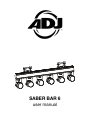
SABER BAR 6
user manual

2
©2019 ADJ PRODUCTS LLC all rights reserved. Information, specifications, diagrams, images, and
instructions herein are subject to change without notice. ADJ logo and identifying product names
and numbers herein are trademarks of ADJ PRODUCTS LLC. Copyright protection claimed includes
all forms and matters of copyrightable materials and information now allowed by statutory or judicial
law or hereinafter granted. Product names used in this document may be trademarks or registered
trademarks of their respective companies and are hereby acknowledged. All non-ADJ brands and
product names are trademarks or registered trademarks of their respective companies.
ADJ PRODUCTS LLC and all affiliated companies hereby disclaim any and all liabilities for property,
equipment, building, and electrical damages, injuries to any persons, and direct or indirect economic
loss associated with the use or reliance of any information contained within this document, and/or as
a result of the improper, unsafe, insufficient and negligent assembly, installation, rigging, and
operation of this product.
ADJ PRODUCTS LLC USA
6122 S. Eastern Ave. Los Angeles, CA 90040
ADJ SUPPLY Europe B.V
Junostraat 2 6468 EW Kerkrade, The Netherlands
+31 (0)45 546 85 00 | Fax +31 45 546 85 99 | www.adj.eu | [email protected]
ADJ PRODUCTS GROUP Mexico
AV Santa Ana 30 Parque Industrial Lerma, Lerma, Mexico 52000
+52 (728) 282-7070 | [email protected]
Energy Saving Matters (EuP 2009/125/EC)
Saving electric energy is a key to help protecting the environment. Please turn off all electrical
products when they are not in use. To avoid power consumption in idle mode, disconnect all
electrical equipment from power when not in use. Thank you!
DOCUMENT VERSION
An updated version of this document may be available online.
Please check www.adj.com for the latest revision/update of this document before beginning
installation and use.
Date
Document
Version
Software
Version
Notes
6/5/19
1
≥ 1.01
Initial release.

3
CONTENTS
General Information
4
Limited Warranty (USA Only)
5
Safety Guidelines
6
Maintenance Guidelines
8
Fixture Overview
9
DMX Setup
11
Installation Instructions
13
System Menu
14
DMX Channels / Values / Functions
18
Dimmer Curve Chart
22
Remote Operating Instructions
23
Multiple Unit Power Linking
24
Master / Slave Set up
24
Optional Lens / Fuse Replacement / Cleaning
24
Trouble Shooting Tips and FAQ
25
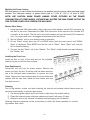
Technical Specifications and Optional Accessories
26
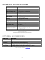
Dimensions
27

4
GENERAL INFORMATION
INTRODUCTION
Please read and understand all instructions in this manual carefully and thoroughly before attempting to
operate these products. These instructions contain important safety and use information.
UNPACKING
The products in this kit have been thoroughly tested and have been shipped in perfect operating condition.
Carefully check the shipping carton for damage that may have occurred during shipping. If the carton appears
to be damaged, carefully inspect each unit included for damage and be sure all accessories necessary to
operate the units have arrived intact. In the event damage has been found or parts are missing, please
contact our customer support team for further instructions. Please do not return this kit to your dealer without
first contacting customer support at the number listed below. Please do not discard the shipping carton in the
trash. Please recycle whenever possible.
WARRANTY RETURNS
All returned service items whether under warranty or not, must be freight pre-paid and accompany a return
authorization (R.A.) number. The R.A. number must be clearly written on the outside of the return package. A
brief description of the problem as well as the R.A. number must also be written down on a piece of paper
and included in the shipping container. If the unit is under warranty, you must provide a copy of your proof of
purchase invoice. Items returned without a R.A. number clearly marked on the outside of the package will be
refused and returned at customer’s expense. You may obtain a R.A. number by contacting customer support.
CUSTOMER SUPPORT
Contact ADJ Service for any product related service and support needs.
Please visit forums.a d j.co m with questions, comments or suggestions.
ADJ SERVICE USA - Monday - Friday 8:00am to 4:30pm PST
800-322-6337 | Fax 323-832-2941 | [email protected]
ADJ SERVICE EUROPE - Monday - Friday 08:30 to 17:00 CET
+31 45 546 85 60 | Fax +31 45 546 85 96 | [email protected]
REPLACEMENT PARTS please visit parts.adj.com
FCC RADIO FREQUENCY INTERFERENCE WARNINGS & INSTRUCTIONS
This product has been tested and found to comply with the limits as per Part 15 of the FCC Rules. These
limits are designed to provide reasonable protection against harmful interference in a residential installation.
This device uses and can radiate radio frequency energy and, if not installed and used in accordance with the
included instructions, may cause harmful interference to radio communications. However, there is no
guarantee that interference will not occur in a particular installation. If this device does cause harmful
interference to radio or television reception, which can be determined by turning the device off and on, the
user is encouraged to try to correct the interference by one or more of the following methods:
• Reorient or relocate the device.
• Increase the separation between the device and the receiver.
• Connect the device to an electrical outlet on a circuit different from which the radio receiver is connected.
• Consult the dealer or an experienced radio/TV technician for help.

5
LIMITED WARRANTY (USA ONLY)
A. ADJ Products, LLC hereby warrants, to the original purchaser, ADJ Products, LLC products to be free of
manufacturing defects in material and workmanship for a prescribed period from the date of purchase (see
specific warranty period on reverse). This warranty shall be valid only if the product is purchased within the United
States of America, including possessions and territories. It is the owner’s responsibility to establish the date and
place of purchase by acceptable evidence, at the time service is sought.
B. For warranty service, you must obtain a Return Authorization number (RA#) before sending back the
product-please contact ADJ Products, LLC Service Department at 800-322-6337. Send the product only to
the ADJ Products, LLC factory. All shipping charges must be pre-paid. If the requested repairs or service
(including parts replacement) are within the terms of this warranty, ADJ Products, LLC will pay return shipping
charges only to a designated point within the United States. If the entire instrument is sent, it must be shipped in
its original package. No accessories should be shipped with the product. If any accessories are shipped with the
product, ADJ Products, LLC shall have no liability whatsoever for loss of or damage to any such accessories, or
for the safe return thereof.
C. This warranty is void of the serial number has been altered or removed; if the product is modified in any manner
which ADJ Products, LLC concludes, after inspection, affects the reliability of the product, if the product has been
repaired or service by anyone other than ADJ Products, LLC factory unless prior written authorization was issued
to purchaser by ADJ Products, LLC; if the product is damaged because not properly maintained as set forth in the
instruction manual.
D. This is not a service contact, and this warranty does not include maintenance, cleaning or periodic check up.
During the period specified above, ADJ Products, LLC will replace defective parts at its expense with new or
refurbished parts, and will absorb all expenses for warrant service and repair labor by reason of defects in material
or workmanship. The sole responsibility of ADJ Products, LLC under this warranty shall be limited to the repair of
the product, or replacement thereof, including parts, at the sole discretion of ADJ Products, LLC. All products
covered by this warranty were manufactured after August 15, 2012, and bear identifying marks to that effect.
E. ADJ Products, LLC reserves the right to make changes in design and/or improvements upon its products without
any obligation to include these changes in any products theretofore manufactured.
F. No warranty, whether expressed or implied, is given or made with respect to any accessory supplied with products
described above. Except to the extent prohibited by applicable law, all implied warranties made by ADJ Products,
LLC in connection with this product, including warranties of merchantability or fitness, are limited in duration to the
warranty period set forth above. And no warranties, whether expressed or implied, including warranties of
merchantability or fitness, shall apply to this product after said period has expired. The consumer’s and/or Dealer’s
sole remedy shall be such repair or replacement as is expressly provided above; and under no circumstances shall
ADJ Products, LLC be liable for any loss or damage, direct or consequential, arising out of the use of, or inability
to use, this product.
G. This warranty is the only written warranty applicable to ADJ Products, LLC Products and supersedes all prior
warranties and written descriptions of warranty terms and conditions heretofore published.
LIMITED WARRANTY PERIODS
• Non L.E.D. Lighting
Products
= 1-year (365 days) Limited
Warranty
(Such as: Special Effect Lighting,
Intelligent Lighting, UV lighting, Strobes, Fog Machines, Bubble Machines, Mirror Balls, Par Cans, Trussing,
Lighting Stands etc. excluding LED and lamps)
• Laser
Products
= 1 Year (365 Days) Limited
Warranty
(excludes laser diodes which have 6 month limited
warranty)
• L.E.D.
Products
= 2-year (730 days) Limited
Warranty
(excluding batt eries which have a 180 day limited
warranty)
Note: 2 Year
Warranty
only applies to
purchases
within the United
States.
• StarTec Series = 1 Year Limited
Warranty
(excludin g batteries which have a 180 day limited warranty)
• ADJ DMX
Controllers
= 2 Year (730 Days) Limited
W
arranty

6
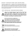
SAFETY INSTRUCTIONS AND GUIDELINES
To guarantee a smooth operation, it is important to follow all instructions and guidelines in this
manual. ADJ PRODUCTS LLC is not responsible for injury and/or damages resulting from the
misuse of these devices due to the disregard of the information printed in this manual. Only qualified
and/or certified personnel should perform installation of these devices and only the original rigging
parts included with these devices should be used for installation. Any modifications to these devices
and/or the included mounting hardware will void the original manufactures warranty and increase the
risk of damage and/or personal injury.
PROTECTION CLASS 1 – DEVICES MUST BE PROPERLY GROUNDED
THERE ARE NO USER SERVICEABLE PARTS INSIDE THESE DEVICES. DO NOT
ATTEMPT ANY REPAIRS YOURSELF; DOING SO WILL VOID YOUR
MANUFACTURES WARRANTY. DAMAGES RESULTING FROM MODIFICATIONS TO
THESE DEVICES AND/OR THE DISREGARD OF SAFETY INSTRUCTIONS AND
GUIDELINES IN THIS MANUAL VOID THE MANUFACTURES WARRANTY AND ARE
NOT SUBJECT TO ANY WARRANTY CLAIMS AND/OR REPAIRS.
DO NOT PLUG THIS UNIT INTO A DIMMER PACK!
DO NOT REMOVE THE COVER UNDER ANY CONDITIONS!
NEVER OPERATE THIS UNIT WITH THE COVER REMOVED!
UNPLUG POWER DURING LONG PERIODS OF NON-USE
NEVER TOUCH LIGHT DURING OPERATION, AS IT MAY BE HOT!
KEEP FLAMMABLE MATERIALS AWAY FROM THESE DEVICES!
INDOOR / DRY LOCATIONS USE ONLY!
DO NOT EXPOSE DEVICES TO RAIN AND/OR MOISTURE!
NEVER LOOK DIRECTLY INTO THE LIGHT SOURCE!
RETINA INJURY RISK - MAY INDUCE BLINDNESS!
SENSITIVE PERSONS MAY SUFFER AN EPILEPTIC SHOCK!

7
SAF ETY I N STRUCT I ONS A ND GUI D E L I N E S
DO NOT position devices close to any FLAMMABLE MATERIALS while operating.
DO NOT attempt installation and/or operation of devices without knowledge how to do so.
DO NOT permit operation by persons who are not qualified to operate these types of devices.
DO NOT shake devices, avoid brute force when installing and/or operating.
DO NOT operate these devices if the main power cord has become frayed, crimped and/or
damaged. Replace any damaged power cords with a similar power rating.
DO NOT remove or break-off the ground plug from the device power cords.
DO NOT remove disassemble devices, there are NO user serviceable parts inside.
ALWAYS disconnect devices from main power source before performing any cleaning.
ALWAYS be sure to install these devices in an area that will allow proper ventilation.
NEVER remove the ground prong from the power cable.
Power cords should be safely routed and secured so they are not likely pinched.
Disconnect power cords during long periods of non-use.
Only use recommended rigging hardware as described in this guide.
Use the original packaging and materials to transport these devices in for service.
These devices should be serviced by qualified service personnel when:
• The power cords or plugs have become damaged.
• Objects have fallen on and/or liquid has spilled into the devices.
• The devices have been exposed to rain and/or moisture.
• The devices do not operate normally or exhibit a marked change in performance.
DO NOT DISCONNECT ANY OF THE POWER CABLES FROM
ANY OF THE 6 FIXTURES WHEN THE BAR IS POWERED ON.

8
MAINTENANCE GUIDELINES
DISCONNECT POWER BEFORE PERFORMING ANY MAINTENANCE!
THERE ARE NO USER SERVICEABLE PARTS INSIDE THESE DEVICES, PLEASE REFER
ALL OTHER SERVICE ISSUES TO AN AUTHORIZED ADJ SERVICE CENTER.
CLEANING
Frequent cleaning is recommended to insure proper function, optimized light output, and an
extended life. The frequency of cleaning depends on the environment in which the device operates
in: damp, smoky or particularly dirty environments can cause greater accumulation of dirt on the lens
and/or light fixture optics. Clean the external housing of the fixture and the front lens of the light at
least every 30-60 days with a soft cloth to avoid dirt/debris accumulation.
NEVER use alcohol, solvents, or ammonia-based cleaners.
MAINTENANCE
Regular inspections are recommended to insure proper function and extended life.
There are no user serviceable parts inside these devices, please refer all other service issues to an
authorized ADJ service technician. Should you need any spare parts, please order genuine parts
from your local ADJ dealer.
Please refer to the following points during routine inspections:
A detailed review by an approved electrical engineer every three months, to make sure the circuit
contacts are in good condition and prevent overheating.
Be sure all screws and fasteners are securely tightened at all times. Lose screws may fall out during
normal operation resulting in damage or injury as larger parts could fall.
Check for any deformations on the light, light housings, lenses, rigging hardware and rigging points
(ceiling, suspension, trussing). Deformations could allow for dust to enter into the devices. Damaged
rigging points or unsecured rigging could cause the devices to fall and seriously injure a person(s).
Electric power supply cables must not show any damage, material fatigue or sediments.

9
OVERVIEW
FRONT
Included items
1 –
Saber Spot WW: 15W Warm White LED (x6)
2 –
Frost Filter: 10° (x6) and 45° Filter (x6)
3 –
Filter Retainer Ring: (x6)
4 –
Omega Bracket: Top (x2)
5 –
Omega Bracket: Bottom (x2)
6 –
Bracket Knob: (x2)
7 –
Linear Base: 1 meter with built-in power and DMX Connections (see next page)
8 –
Head Mounting Knob: (x6)
9 –
RF Remote Control: (Not pictured above.) See page 23 for instructions.
10 –
Safety Cable: (x2) (Not included or pictured above.) See page 13 for instructions.
11 –
Power Cable: (Not pictured above.)
1
2
3
4
5
6
7
8

10
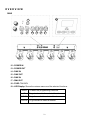
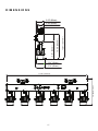
OVERVIEW
REAR
12 –
POWER IN
13 –
POWER OUT
14 –
DMX IN
15 –
DMX OUT
16 –
DMX IN
17 –
DMX OUT
18 –
FUSE: T2A/250V
19 –
LED Display: Shows the various menus and the selected functions.
MODE
To select the programming functions
UP
To go backward in the selected functions
DOWN
To go forward in the selected functions
ENTER
To go forward or select a function
12
13
14
15
16
17
18
19

11
DMX SETUP
POWER SUPPLY
The Saber Bar 6 contains an automatic voltage switch, which will auto sense the voltage when it is
plugged into the power source. With this switch there is no need to worry about the correct power
voltage, this unit can be plugged in anywhere.
DMX-512
DMX is short for Digital Multiplex. This is a universal
pro
tocol used by most lighting and controller
manufactures as a form
of
communication between intelligent fixtures and controllers. A DMX
controller sends DMX data instructions from the controller to the fixture. DMX data is sent as serial
data that travels from fixture to fixture via the DATA “IN” and DATA “OUT” XLR terminals located on
all DMX fixtures (most controllers only have a DATA “OUT” terminal).
DMX LINKING
DMX is a language allowing all makes and models of different manufactures to be linked
together and operate from a single controller, as long as all fixtures and the controller are DMX
compliant. To ensure proper DMX data transmission, when using several DMX fixtures try to
use the shortest cable path possible. The order in which fixtures are connected in a DMX line does
not influence the DMX addressing. For example, a fixture assigned a DMX address of 1 may be
placed anywhere in a DMX line, at the beginning, at
the
end, or anywhere in the middle.
Therefore, the first fixture
contr
olled
by the controller could be the last fixture in the chain. When
a fixture is assigned a DMX address of 1, the DMX controller knows to send DATA assigned to
address 1 to that unit, no matter where it is
located
in the DMX chain.
DATA CABLE (DMX CABLE) REQUIREMENTS
(FOR DMX AND MASTER/SLAVE OPERATION):
The Saber Bar 6 can be controlled via DMX-512 protocol.
The Saber Bar 6 has 8 DMX channel modes (1, 3, 4, 6, 9,
10, 12 and 13 channel mode). The DMX address is set
electronically using the controls on the rear panel of the
unit. Your unit and your DMX controller require an approved
DMX-512 110 Ohm Data cable for data input and data
output (Figure 1). We recommend AccuCable DMX cables. If
you are making your own cables, be sure to use standard
110-120 Ohm shielded cable (This cable be purchased at
almost all professional sound and lighting stores). Your
cables should be made with a male and female XLR
connector on either end of the cable. Also remember that
DMX cable must be daisy chained and cannot be split.
Figure 1

12
DMX SETUP
NOTICE
Be sure to follow figures two and three when making your own cables. Do not use the ground lug on
the XLR connector. Do not connect the cable’s shield conductor to the ground lug or allow the
shield conductor to come in contact with the XLR’s outer casing. Grounding the shield could cause
a short circuit and erratic behavior.
SPECIAL NOTE: LINE
TERMINATION
When longer runs of cable are used, you may need to use a terminator on the last unit to avoid
erratic behavior. A terminator is a 110-120 ohm 1/4 watt resistor, which is con nected between pins 2
and 3 of a male XLR connector (DATA + and DATA -). This unit is inserted in the female XLR
connector of the last unit in your daisy chain to terminate the line. Using a cable terminator (ADJ part
number Z-DMX/T) will decrease the possibilities of erratic behavior.
Figure 4
DMX512 IN
3-PIN XLR

13
INSTALLATION INSTRUCTIONS
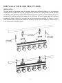
INSTALLATION
This unit should be mounted using a mounting clamp (not provided), affixing it to the mounting
bracket that is provided with the unit. Always ensure that the unit is firmly fixed to avoid vibration
and slipping while operating. Always ensure that the structure to which you are attaching the unit is
secure and is able to support the weight of ten (10) times the unit’s weight and any mounting
accessories. Safety cables (not included) are recommended when installing the fixture. It is also
recommended that a professional installs the equipment and it must be installed in a place where it
is out of the reach of people’s grasp.
Safety Cable
(not included)
Safety Cable
(not included)
Pro-Clamps
(not included)

14
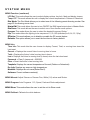
SYSTEM MENU
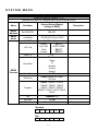
System Menu
Supports Software Versions ≥ 1.01
Features are subject to change without any prior written notice
Menu
Sub Menu
Options/Values (Default
settings in BOLD)
Description
MENU
Address
Set ADDR 001
001-507
MENU
Mode
UserMode
1/3/4/6/9/10/12 and 13CH
MENU
Function
No DMX
Hold/Black/Program
LCD. Set
Display
ON/OFF
Key Lock
ON/ON1/OFF
Flash
ON/OFF
Inverse
OFF/ON
Temp. C/F
C/F
Dim Mode
Standard
Stage
TV
Architec
Theatre
Stage 2
MasterSw
On/Off
DimCurve
Linear/Square/INV.Squa/
S-Curve
Frequen
900HZ, 1000HZ, 1100HZ,
1200HZ, 1300HZ, 1400HZ,
1500HZ, 2500HZ, 4000HZ,
5000HZ, 10kHZ, 15kHZ, 20kHZ,
25kHZ
Flip
Standard/Flip
RFActive
On/Off
Defaults
Reset? / Cancel
Factory default set
Standard
1
2
3
4
5
6
Flip
6
5
4
3
2
1

15
SYSTEM MENU
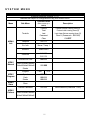
System Menu
Supports Software Versions ≥ 1.01
Features are subject to change without any prior written notice
Menu
Sub Menu
Options/Values
(Default settings in
BOLD)
Description
MENU
Info
TimeInfo
Current
Current fixture running time (H)
Total
Fixture total running time (H)
Last
Last clear fixture running time (H)
Password
Clear 0: (Password = 050/060)
Clear
ON/OFF
TempInfo
XXX C/F
Err. Info
None / Temp 1
ModelInf
Saber Bar 6
Software
1UV1.01
2UV1.01
MENU
Manual
Dimmer/Dim Fine
000-255
White1/White2/White3/
White4/White5/White6/
Strobe
000-255
MENU
Program
Program
Flow
1-13
Speed
000-255
Fade
000-255
Strobe
000-255
MENU
Slave
Slave
MENU
Calibrat
Calibrat Password
000-255
White balance (Password = 050)
White1/White2/White3/
White4/White5/White6

16
SYSTEM MENU
LCD CONTROL PANEL LOCKOUT
When Key Lock menu is set to ON, the LCD backlight will turn OFF after 30 seconds and the
Control Panel will lock and the display will show LOCKED*****.
Press and hold the MODE button for 5 seconds to unlock.
When Key Lock menu is set to ON1, the LCD backlight will turn OFF after 30 seconds and the
Control Panel will lock and the display will show LOCKED*****.
To unlock the Control Panel, follow these steps:
1. When locked, the display will show: LOCKED*****
2. Press UP, then the display will change to: LOCKED**** (one * disappears)
3. Press DOWN, then the display will change to: LOCKED*** (two * disappear)
4. Press UP, then the display will change to: LOCKED** (three * disappear)
5. Press DOWN, then the display will change to: LOCKED* (four * disappear)
6. Press ENTER, then the display will change to LOCKED and then become unlocked.
DMX Mode: Operating through a DMX controller gives the user the freedom to create their own
programs tailored to their own individual needs. See pages 18-21 for each mode’s DMX traits.
Press the MODE button to select the DMX mode.
MENU Addressing and MENU Mode: This function will allow you to control each individual
fixture’s traits with a standard DMX 512 controller.
1. To run your fixture in DMX mode press the MODE button until MENU Address is displayed
and press ENTER. “Set ADDR XXX” represents the current displayed DMX address.
2. Use the UP or DOWN buttons to select your desired DMX address, then press the ENTER
button to select your DMX Channel mode.
3. Use the UP or DOWN button to scroll through the DMX Channel modes (1CH, 3CH, 4CH,
6CH, 9CH, 10CH, 12CH, and 13CH).
MENU Function:
No DMX Setup: This mode allows the unit to default to one of three modes if the DMX signal
is lost or interrupted.
1. Press the ENTER button to select your setting.
2. Press the UP or DOWN button to select one of the three options.
HOLD = the unit will hold the last state before the signal was lost.
BLACK = if the DMX signal is lost or interrupted, the unit will automatically go
into stand by mode.
PROGRAM = the unit will run the default internal programs.

17
SYSTEM MENU
MENU Function: (continued)
LCD Set: This mode allows the user to select display options, key lock, flash and display inverse.
Temp. C/F: This mode allows the unit to display the current temperature in Celsius or Fahrenheit.
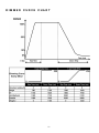
Dim Mode: The Dim Mode allows you to select one of the following preset dimming modes: See
page 22 for dimming curve chart.
MasterSW: This mode allows the user to turn ON/OFF the DMX signal output when in Master Mode.
DimCurve: This mode allows the user to select one of four dimmer curve options.
Frequen: This mode allows the user to select the desired frequency/flicker.’
Flip: This mode allows the lighting to be sequenced 1,2,3,4,5,6 (standard) to 6,5,4,3,2,1 (flip).
RFActive: This mode allows you to disable or enable the RF remote feature.
Defaults: This option allows you to reset the functions to factory default.
MENU Info:
Time Info: This mode lets the user choose to display Current, Total, or running time since the
Last reset.
Current = Displays the current fixture’s running time in hours.
Total = Displays the fixture’s total running time in hours.
Last = Displays the fixture’s running time (in hours) since the last clear/reset.
Password = Clear 0: (password = 050/060)
Clear = Reset the fixture’s Last running time.
TempInfo: Displays the current temperature of the unit (Celsius or Fahrenheit).
Err. Info: Displays any errors or high temperature.
ModelInf: Displays the unit name (Saber Bar 6).
Software: Current software version(s).
MENU Manual: Adjust Dimmer or Dimmer Fine, White (1-6) values and Strobe.
MENU Program: Auto Programs 1-13, Speed, Fade and Strobe adjustment.
MENU Slave: This mode allows the user to set the unit to Slave mode.
MENU Calibrat: Calibrate the white balance.

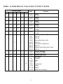
18
DMX CHANNELS/VALUES/FUNCTIONS
Channel Modes
Value
Function
1Ch
3Ch
4Ch
6Ch
9Ch
10Ch
1
1
1
1
1
1
0-255
Head 1:
0~100%
1
1
1
2
2
2
0-255
Head 2:
0~100%
1
1
1
3
3
3
0-255
Head 3:
0~100%
1
1
1
4
4
4
0-255
Head 4:
0~100%
1
1
1
5
5
5
0-255
Head 5:
0~100%
1
1
1
6
6
6
0-255
Head 6:
0~100%
2
7
7
Shutter and Strobe Effect
0-31
LEDs Off
32-63
LEDs On
64-95
Strobe effect slow to fast
96-127
LEDs On
128-159
Pulse effect in sequences
160-191
LEDs On
192-223
Random strobe effect slow to fast
224-255
LEDs On
2
3
8
8
0-255
Dimmer (intensity)
Intensity 0 to 100%
3
4
9
9
0-255
Dimmer Fine 16-bit
10
Dim Mode
0-20
Standard
21-40
Stage
41-60
TV
61-80
Architectural
81-100
Theatre
101-120
Stage 2
121-255
Default to Unit Setting

19
DMX CHANNELS/VALUES/FUNCTIONS
Channel Mode
Value
Function
10Ch
1
0-255
Head 1:
0~100%
2
0-255
Head 2:
0~100%
3
0-255
Head 3:
0~100%
4
0-255
Head 4:
0~100%
5
0-255
Head 5:
0~100%
6
0-255
Head 6:
0~100%
7
Shutter and Strobe Effect
0-31
LEDs Off
32-63
LEDs On
64-95
Strobe effect slow to fast
96-127
LEDs On
128-159
Pulse-effect in sequences
160-191
LEDs On
192-223
Random strobe effect slow to fast
224-255
LEDs On
8
0-255
Dimmer (intensity)
Intensity 0 to 100%
9
0-255
Dimmer Fine 16-bit
10
Dim Mode
0-20
Standard
21-40
Stage
41-60
TV
61-80
Architectural
81-100
Theatre
101-120
Stage 2
121-255
Default to Unit Setting

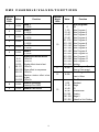
20
DMX CHANNELS/VALUES/FUNCTIONS
Channel Mode
Value
Function
12Ch
1
0-255
Head 1:
0~100%
2
0-255
Head 1 Fine 16-bit
3
0-255
Head 2:
0~100%
4
0-255
Head 2 Fine 16-bit
5
0-255
Head 3:
0~100%
6
0-255
Head 3 Fine 16-bit
7
0-255
Head 4:
0~100%
8
0-255
Head 4 Fine 16-bit
9
0-255
Head 5:
0~100%
10
0-255
Head 5 Fine 16-bit
11
0-255
Head 6:
0~100%
12
0-255
Head 6 Fine 16-bit
Page is loading ...
Page is loading ...
Page is loading ...
Page is loading ...
Page is loading ...
Page is loading ...
Page is loading ...
Page is loading ...
-
 1
1
-
 2
2
-
 3
3
-
 4
4
-
 5
5
-
 6
6
-
 7
7
-
 8
8
-
 9
9
-
 10
10
-
 11
11
-
 12
12
-
 13
13
-
 14
14
-
 15
15
-
 16
16
-
 17
17
-
 18
18
-
 19
19
-
 20
20
-
 21
21
-
 22
22
-
 23
23
-
 24
24
-
 25
25
-
 26
26
-
 27
27
-
 28
28


ADJ Saber Bar 6 User manual
- Category
- Stroboscopes & disco lights
- Type
- User manual
Ask a question and I''ll find the answer in the document
Finding information in a document is now easier with AI
Related papers
-
ADJ FOC369 User manual
-
-
-
ADJ DOT903 User manual
-
-
-
-
-
ADJ SAB605 Saber Spot WW Compact Pinspot Light User manual
-
Other documents
-
Eliminator Lighting FROST FX BAR W Eliminator Lighting User manual
-
soundsation LED-STR864 Product Instruction
-
Eliminator Lighting Frost FX BAR RGBW LED Fixture User manual
-
ACME Flandina 12 User manual
-
Parmida LED Technologies PLED-UC12V-6KW-6P Installation guide
-
Elation DarkFX UV Wash 2000 User manual
-
-
-
Contest PIN15W User guide
-
Rockville Best Strip 60 Pack Owner's manual