Page is loading ...

MODEL 96XX
SPEECH
INSTALLATION GUIDE
PCI KEYPAD NOT INSTALLED
TDN 07103-10023-00
March 27, 2012
CORPORATE HEADQUARTERS:
21405 B S
TREET
LONG BEACH, MS 39560
P
HONE: (800) 259-6672
F
AX: (228) 868-9445
RMA (RETURN MATERIAL A UTHORIZATION)
RETURN ADDRESS:
21405 A
VENUE “B”
L
ONG BEACH, MS 39560
© 2012 Triton. All Rights Reserved. TRITON logo is a
registered trademark of Triton Systems of Delaware, LLC

2
MULTIFUNCTION/SPEECH INSTALLATION GUIDE
** Important **
The upgrade procedures require removal and replacement of electrostatic
sensitive devices such as integrated circuits, boards, and assemblies. ESD
wrist straps should be worn and connected to a common ground point to
prevent hazardous electrostatic discharge to sensitive components. Failure
to follow proper handling or use of these items may result in damage from
ESD.
* WARNING NOTE *
• The 9XXX Software required with this upgrade may be obtained
from the Triton partner web site. Always use the latest version of software.
• You must have your EPROM access code to load software. DO NOT
begin the hardware installation without this code. If you do not have this
code, the memory module and multifunction board must be returned to Triton
to reset. Call Triton Technical Support (800.259.6672) for clarification.
Updates:
November 30, 2011 Original.
March 15, 2012 Edits to clarify EPROM access code requirement.
March 27, 2012 picture edits

3
MULTIFUNCTION/SPEECH INSTALLATION GUIDE
This guide covers the steps for installing a speech (headphone jack) kit for
Model 96XX ATMs. It is independent of the PCI keypad upgrade. This proce-
dure includes a list of tools and hardware required for the upgrade as well as the
steps involved.
SCOPE
INTRODUCTION
This procedure applies to all service personnel involved in the process of
maintaining or converting Triton ATMs.
REQUIRED PARTS AND TOOLS
* IMPORTANT *
The Speech upgrade for the 96XX ATM requires:
 SD04.01 EPROM or higher installed in the Memory Module (SS-2).
 Multi-function module (new).
 Software upgrade.
DERIUQERSLOOT
)citengaM(revirdwercSspillihP2#)"61/7dna"8/1(stibllirddnallirD
revirDtuN)mm11("61/7reluRr
oerusaeMepaT
)licneP(rekraM
TIKNOITALLATSNIHCEEPSXX69
)32001-00260N/P(
DEILPPUSSTRAP
REBMUNTRAP NOITPIRCSED YTITNAUQ
41400-01190ylbmessadraobnoitcnuf-itluM1
01400-02190
lbaCenohpdaeH
e
1
55010-11030
ilCreniateRkcaJhceepS
p
1
20000-27020
senraHeriWdedurtxE,pilC
s
1
51070-02190
riWdnuorG
e
retpadA
1
90000-27030evisehdAtiudnaP,pilC2
01000-03010
etirreF1
52010-0319010.40DSnoisreV,morpE1
10883-00070
lliarB,lebaL
e
1

4
MULTIFUNCTION/SPEECH INSTALLATION GUIDE
Installation
Follow these steps to install the speech installation kit for the Model 96XX
ATM:
1. Unlock and open the control panel. Verify that the power switch is in the
OFF (0) position. Close the control panel.
2. Using a tape measure/ruler, mark a point 1- 1/2" from the bottom left edge
shown in Figure 1. From
that mark, measure 1-1/2” down and place another
mark (Figure 2).
This will be the drill point. Erase the previous mark. Figure
3 shows the drill point location.
Figure 3. Drill point location.
Figure 1. Measure 1-1/2" across.
Figure 2. Measure 1-1/2" down.
* Important *
When routing the headphone cables in the control panel, it is critical
that cables are isolated from the main ribbon cable that runs from the
card cage to the keypad. DO NOT ROUTE/SECURE HEADPHONE
CABLE WITH THIS RIBBON CABLE!

5
MULTIFUNCTION/SPEECH INSTALLATION GUIDE
3. Drill a pilot hole using the 1/8” drill bit and finish using the 7/16" bit (Figures
4 and 5).
4. Open the control panel and feed the headphone cable (audio jack side first,
Figure 6) through the hole (exterior) until the headphone plug is flush in the
hole (Figure 7).
Figure 4. Drill pilot hole. Figure 5. Finish with 7/16" bit.
Figure 6. Feed cable in hole. Figure 7. Headphone plug flush.
5. (Inside control panel) Secure the headphone plug with the retainer clip
shown in Figure 8. Insert the retainer clip half way.
Figure 8. Insert retainer clip to secure.

6
MULTIFUNCTION/SPEECH INSTALLATION GUIDE
6. Using a 7/16" nutdriver, remove the bolt shown in Figure 9. Install the ground
wire adapter and secure with bolt previously removed (Figure 10). Connect
the ground wire from the headphone cable to this adapter.
Figure 9. Remove bolt.
Figure 10. Install ground wire adapter.
7. Install an extruded wire harness clip to the speaker screw shown in Figure 11.
Route the cable under and through the clip so cable has a “bow”. Next,
install the adhesive-backed clip between the 2 center-pin torx screws (figure
12). Figure 13 shows the headphone cable routing.
Figure 11. Install clip and
route cable.
Figure 12. Install flat clip and
secure cable.
Figure 13. Cable routing.
Cable routing

7
MULTIFUNCTION/SPEECH INSTALLATION GUIDE
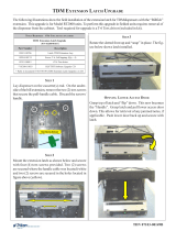
9. Step nine omitted
8. Pull the Memory module from the card cage (SS-2) and verify the EPROM
version is 04.01 or higher (Figure 14). If not, install the required upgraded
EPROM (included in kit) following ESD precautions and correct orientation
of the chip (see pages 8 and 9 for Chip Replacement Procedures). Reinstall
the memory module after completion.
Figure 14. Memory module
EPROM location.
10. The required Multi-function/Speech module will be installed in slot 4 (SS-4)
beneath the Modem module. Figure 16 shows the card cage configuration.
IMPORTANT NOTES:
• Port ONE of the Multi-function board is ONLY for the PCI keypad upgrade.
Do not plug anything else into this port.
• The Multi-function board will NOT provide power to a scrolling LED sign.
• Remove the memory expansion board, as it is not required. If you have a
memory expansion module, and wish to retain it, move jumper J1 & J2 to pins
2-3 (Aux 2) as shown on the circuit card. Place the expansion module in slot
5 (SS5). AFTER SOFTWARE DOWNLOAD. Figure 16 below shows the
module installed.
• Software and graphics must be reloaded.
Figure 16. Card cage configured.

8
MULTIFUNCTION/SPEECH INSTALLATION GUIDE
11. Open the ferrite included in kit. Wrap the headphone cable in the ferrite as
shown in Figure 17. Position the ferrite as close as possible to the headphone
jack and snap ferrite together. Plug the headphone jack into the jack provided
on the Multi-function/Speech module shown in Figure 18.
12. Secure any excess cable to the cable
clip shown in Figure 19.
Figure 17. Install cable in ferrite.
Figure 18. Connect cable to
Multi-function module.
Figure 19. Secure excess cable.
13. Affix the Braille label approximately
1/4" to the right of the headphone
plug as shown in Figure 20. Ensure
correct orientation of label .
Figure 20. Affix Braille label.

9
MULTIFUNCTION/SPEECH INSTALLATION GUIDE
Removal/Replacement of EPROM Chip if Required
1. Remove the SS-2 card (Memory module) from its slot in the card cage. Place the
memory module on a flat surface (preferably on an ESD mat). Position the card
so that the front of the module is facing towards you (Figure 1).
Remove this chip
2. Remove the EPROM chip that is immediately to the left of the circular battery
(see Figure 1). The use of an IC chip puller to perform this step is recom-
mended; however, a small flat-blade screwdriver can be used. Place the tip of
the screwdriver between the chip and its socket, and twist the tip slightly to
begin lifting the chip from the socket. Move the tip of the screwdriver to the
opposite end of the chip and repeat. By alternating sides and lifting the chip
a small amount each time, you will eventually release the chip from its socket.
At this point, carefully remove the chip from the memory card.
3. Take the new EPROM (SD04.01) and place it lightly on the chip socket, en-
suring that the half-circle notch on the chip is positioned to the
left (see
Figure 2). Align the pins of the chip with the insertion holes of the socket.
Figure 1. Memory module.
Figure 2. Eprom chip (Memory module).
Notch

10
MULTIFUNCTION/SPEECH INSTALLATION GUIDE
4. It may be necessary to bend the pins on one or both edges of the chip inward
very slightly to achieve this alignment. To do this, grasp the left and right-
hand edges of the chip and orient the chip so that the pins are facing you
(Figure 3). Place the pins on one side of the chip on a flat surface and apply
mild pressure to bend the pins by angling the top edge of the chip toward
you. Check the alignment of the pins with the socket as before. If necessary,
bend the pins on the opposite edge of the chip.
Figure 3. Rotate chip to bend pins inward.
5. Once the pins of the chip line up with the socket holes, insert the chip into
the socket by applying an even pressure to the chip to seat it firmly in the
socket. Make sure the chip is oriented properly (notch to the left). Make sure
the pins are inserted correctly and that none are bent.
6. Reinstall the memory module into the card cage slot.

11
MULTIFUNCTION/SPEECH INSTALLATION GUIDE
SOFTWARE DOWNLOAD
ACCESSING THE EPROM DIAGNOSTICS
The EPROM DIAGNOSTICS menu will be used to prepare the terminal for the
software download. To access the EPROM main menu you will need the EPROM
Access Code. If you do not have the access code, the memory module and
multifunction board must be returnedd to Trion for reset.
1. While holding down the “1” key on the Terminal main keypad, reset the unit
by turning the AC Power Switch OFF for a few seconds, then back ON
again. The terminal will perform a series of boot-up diagnostics. At the
conclusion of the boot-up sequence the unit should now display a screen
requesting an EPROM access code. Release the “1” key. Consult with your
distributor for the access code for the terminal.
2. Enter the EPROM access code. The unit will display an EPROM Diagnostics
menu:
3. Press the ERASE PROGRAM option. A warning screen is displayed:
DIAGNOSTICS
CHANGE PASS
ERASE PROGRAM
ERASE EEPROM
RESTART
DOWNLOAD
SET CON/VOL
* IMPORTANT *
The EPROM chip and all associated hardware required must be installed and
the EPROM
must be erased prior to downloading the operating software. DO
NOT load an update file over current Triton Standard software running the
machine.
The terminal software must be loaded using the TriComm for Windows®
executable program found on the Triton partner web site, along with the latest
9600 software. The following procedures describe accessing the terminal Eprom
Diagnostic screen and running the TriComm for Windows program.

12
MULTIFUNCTION/SPEECH INSTALLATION GUIDE
4. Enter the Erase Program code of 2455. When the erase operation is
completed the main menu will appear.
5. Press the ERASE EEPROM option. A warning screen is displayed, as in
step 3.
6. Enter the Erase EEPROM code of 2455. When the erase operation is
completed the main menu will appear.
7. Press the key next to the DOWNLOAD PROGRAM option. The next screen
will present a message prompting you to connect the PC to the Terminal and
begin the software transfer:
CONNECT THE DOWNLOAD CABLE
1. Connect the 9-pin adapter end of the download cable to the selected serial
port on the PC. Note the serial port you are using (COM1 or COM2 ) for use
in configuring the TriComm for Windows program. See the figures below
for connector location:
** WARNING **
This selection will erase part of the unit’s memory and should be
used only with caution!
Enter the erase code to proceed or cancel to end.
** PROGRAM LOAD **
Connect the PC to the unit or connect phone
line.
Begin the transfer on the PC.

13
MULTIFUNCTION/SPEECH INSTALLATION GUIDE
2. Unlock and open the control panel of the terminal. Connect the other end of
the download cable to the load port located on the CPU module shown
below.
Load Port
(CPU)
CONFIGURE TRICOMM FOR WINDOWS PROGRAM
1. Install the TriComm application onto your PC. .
2. Access the Windows Start\Programs menu and select the TriComm option.
Select the WTriComm.exe. file. The program will start. The program’s main
window will be displayed:
3. Click the Settings button. The following dialog window will be displayed:

14
MULTIFUNCTION/SPEECH INSTALLATION GUIDE
4. Choose a Com Port setting that matches the port on the PC. Click the down
arrow on the Com Port control to see additional selections, as shown here:
5. Use the Drive List control to select the location of the software file you
downloaded from Triton and extracted.

15
MULTIFUNCTION/SPEECH INSTALLATION GUIDE
7. The File List box will show the contents of the currently selected directory
on the drive. Here is an example of a file name, this one is for a 9100 ATM:
6. Below is representative of file location.
8. The kinds of load files that will be displayed in the list will depend upon the
ATM model type and the type of load file (Full Load or Update Load)
present on the disk. Highlight the appropriate file and click the Save button
to save the current settings and return to the TriComm main window.

16
MULTIFUNCTION/SPEECH INSTALLATION GUIDE
Start Software Download
1. Click the Load button on the TriComm main window. The software loading
process begins. The Percent Completed progress bar will indicate the degree
of completion of the file transfer. A corresponding progress indicator will
appear on the terminal display during the file transfer, along with the words,
“TRANSFER INITIATED.”
2. Once the file transfer is complete (has reached 100%), the terminal will
perform a check of the received data, as indicated by the words, “CHECKING
FLASH CRC” on the unit’s display.
3. When the words, “DOWNLOAD COMPLETED” appear on the terminal
display, the software load is complete.
REMOVE THE DOWNLOAD CABLE
and close the control panel of the terminal.
4. Press the Cancel key on the keypad to exit the diagnostics menu area and
run the terminal program. The terminal will run a series of verification tests,
after which the terminal’s Top Menu will be displayed.
5. Close the TriComm for Windows program by clicking on the close button in
the upper-right corner of the program window, or by clicking on the title bar
icon in the upper-left corner of the program window and selecting the Close
option from the pop-up menu. Remove the download cable connection
from the PC Com Port.
6. Configure the ATM and ensure operation.
/