Page is loading ...

CN4800 Series
CONTROLLER
Operator's Manual
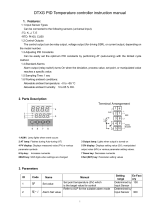
PV
SV
OUT1
OUT2
ALM1
ALM2
SEL
M1791/0502

1
Contents
I. PREPARING THE OPERATION ............................... 4
1. THE BASIC INSTALLATION PROCEDURE .................... 5
2. CHECK OF SPECIFICATIONS ........................................ 6
2.1 CN4800 MODEL CONFIGURATION ....................... 6
3. ACCESSORIES................................................................ 8
4. INSTALLATION ................................................................ 8
4.1 INSTALLATION PLACE ........................................... 8
4.2 INSTALLATION PROCEDURE ................................ 9
4.3 CAUTION ON SAFETY ............................................ 10
4.4 PANEL CUT DIMENSIONS ..................................... 18
5. WIRING ............................................................................ 19
5.1 CN4800 WIRING DIAGRAM
[When the output 1 is relay (SPST) output,
SSR drive output or current output].......................... 19
5.2 CN4800 WIRING DIAGRAM
[When the output 1 is relay (SPDT) output].............. 21
5.3 CN4800 WIRING DIAGRAM
(NOT UNIVERSAL OUTPUT) .................................. 23
5.4 CN4800 WIRING DIAGRAM
(UNIVERSAL OUTPUT) ........................................... 26
5.5 NOTES ..................................................................... 28
II. FRONT PANEL LAYOUT .......................................... 30

2
III. OPERATION PROCEDURE...................................... 33
1. OPERATION MODE/PARAMETER SETTING MODE ..... 33
2. VIEWING PARAMETERS ................................................ 33
3. CHANGING PARAMETERS............................................. 35
IV.SETTING INPUT AND OUTPUT TYPES .................. 37
Changing input ............................................................................. 37
Changing scale (voltage/current input)......................................... 41
Changing output (universal output) .............................................. 42
V. FUNCTIONS .............................................................. 44
Lock .............................................................................................. 44
Auto-tuning ................................................................................... 47
Control function ............................................................................ 51
Alarm ............................................................................................ 55
Ramp soak ................................................................................... 60
Two set-points .............................................................................. 64
Analog output (AO) ....................................................................... 65
Digital output................................................................................. 67
Manual operation.......................................................................... 69
Remote SV ................................................................................... 71
Output monitoring ......................................................................... 72
VI.SET-UP PARAMETER .............................................. 73
Input filter ...................................................................................... 73
PV shift ......................................................................................... 74
Control type .................................................................................. 75
Output setting in input abnormal................................................... 76
Output limits.................................................................................. 77
Set point value limits..................................................................... 78
Output cycle time.......................................................................... 79
Direct/reverse control action......................................................... 81

3
Control processing cycle time....................................................... 82
APPENDIX ...................................................................... 83
1. ERROR MESSAGES........................................................ 83
2. POWER FAILURE ............................................................ 83
3. SPECIFICATIONS............................................................ 84
4. TROUBLESHOOTING...................................................... 89
5. PARAMETER LIST........................................................... 91

4
I. PREPARING THE OPERATION
We thank you for the purchase of this CN4800 (Fuzzy Temperature
Controller).
Employing FUZZY LOGIC the CN4800 virtually eliminates system overshoot
and effectively suppresses fluctuation of the process variable due to
external disturbances.
Please read this manual, when programed and operated within the
guidelines setforth in this manual, your CN4800 controller will give you years of
precise, reliable control.
* E.U. indicates Engineering Units.
CN4800
The product conforms to the requirements of the Electromag-
netic compatibility Directive 89/336/EEC as detailed within the
technical construction file number TN510401. The applicable
standards used to demonstrate compliance are :
EN50081-1 : 1992 Conducted and Radiated emissions
EN50082-1 : 1992 Radiated immunity, ESD and FBT
(The unit meets Class A limits for Conducted Emissions.)
The unit also complies with the part of Immunity standards.
IEC1000-4-2 : 1995 level 3, IEC1000-4-3 : 1995 level 3
IEC1000-4-4 : 1995 level 3, IEC1000-4-8 : 1993 level 4

5
1. THE BASIC INSTALLATION PROCEDURE
Is given here as to the basic flow from the installation to operate the CN4800.
For detailed description of each step, see the pages correspondent. See
the section “Operation Procedure” on the pages 33 to 36 for calls and
changes the specific parameter.
Install the main unit on the panel, using the attached panel
mounting bracket. (See page 8 to 18 for details.)
Connect the unit to power supply and input and output
devices. (See page 19 to 29 for details)
Power up, then select and check input types (such as types
of sensors), input temperature range, decimal point used or
not used and so on. In case of the universal output type,
set and check the output switch pins inside the main unit.
(See page 37 to 43 for details.)
Either the conventional PID control mode or the fuzzy
control mode, which is effective in minimizing overshoot
rate and outer condition effects, can be selected. Select by
setting the parameter , where the default set is PID.
(See page 75 for details.)
System power up then, execute auto-tuning to define the
control parameters. (See page 47 to 50 for details.)
Basic preparations are completed. Carry on settings for the
optional functions (alarm, two set points, transmission,
ramp soak, analog output etc.), following this instruction.
Installation of
Main Unit
Connection
Selecting Input
and Output Types
Selecting PID
or Fuzzy
Tuning
Ready
Normal
Operation
See page 44, as setting values (SV) can be set in the same
manner as the Lock parameter on page 44.

6
2. CHECK OF SPECIFICATIONS
Please make sure that specifications of this product is according with
your request. The product specifications are provided on the main unit
as model configuration following.
2.1 CN4800 MODEL CONFIGURATION
CN4801 4802
123456
R1
DC1
F1
R2
DC2
F2
-AL1
-AL2
HB
*
Number of Outputs
CN4801 - single output
CN4802 - Dual output
Contents
Output #2
Relay
dc pulse
Current (DC 4~20mA)
Output #1
Relay
dc pulse
Current (DC 4~20mA)
Alarm function
1pt.
2pts.
HB alarm
Input type code
Programmed
Input range code
Programmed
Additional function
Digital Input
RS-485 transmission
Auxiliary analog output
Remote SV
Front panel
English
DI
C4
PV
RSP
*

7
2.2 CN4810/20 MODEL CONFIGURATION
CN4810
123456
R1
DC1
F1
R2
DC2
F2
AL1
AL2
HB
*
4820
Front panel dimensions:
48
×
96 mm for CN4810
96
×
96 mm for CN4820
Contents
Number of Outputs
CN48X1 - Single Output
CN48X2 - Dual Output
Alarm function
1pt.
2pts.
HB alarm
Front panel
English
*
DI
C4
PV
RSP
Control output 1
Relay
dc pulse
Current (DC 4~20mA)
Control output 2
Relay
dc pulse
Current (DC 4~20mA)
Input type code
Programmed
Input range code
Programmed
Additional functions
Digital Input
RS-485 transmission
Auxiliary analog output
Remote SV

8
3. ACCESSORIES
In addition to the main unit, the following accessories are shipping in
the same package.
Accessories Quat.
Instruction manual (this manual)
Panel mounting bracket set
Current input resistance (250
Ω
)
* Not delivered for TC/PT input type
1
1
1
* Suffix means revision control
4. INSTALLATION
4.1 INSTALLATION PLACE
Please verify if where the controller is mounted there is no:
(1) splash of water,
(2) mechanical vibration,
(3) extreme temperature
(4) no corrosive gases,
(5) dust or oil smoke,
(6) electric noise.

9
• For CN4800
Slide the enclosed plastic panel mounting bracket (shipped with
the CN4800) up the back of the controller until it makes contact
with the back of the panel. Push the mounting bracket until the
tabs seat themselves in the molded tab ridges, located on the
front of the controller’s outer case. Tighten the two screw on the
mounting bracket for added pressure; do not use excessive
force.
• For CN4810/20
The mounting bracket’s tabs fit into the two holes on both the top
and bottom of the controller’s outer case. With an instrument
screwdriver, turn the screw in the mounting bracket until the end
of it touches the back of the panel. Do this to both brackets.
Making sure that the face of the controller is flush and straight,
tighten both mounting bracket screws. Your controller should
now be firmly set. If the controller is still loose, tighten the
mounting bracket screw a little more. Do not use excessive
force.
4.2 INSTALLATION PROCEDURE
For CN4800
Panel mounting bracket (accessorie)
For CN4810/20
Clamping screw
Panel
Panel
Clamping screw Main unit
Panel mounting bracket (accessorie)

10
4.3 CAUTION ON SAFETY
WARNING
CAUTION
Wrong handling may cause a dangerous situation,
in which there is a possibility of death or heavy
injury.
Wrong handling may cause a dangerous situation,
in which there is a possibility of injury or physical
damage.
First of all, read this "Caution on Safety" carefully,
and then use the instrument in the correct way.
The cautionary descriptions listed here contain important information about
safety, so they should always be observed. Those safety precautions are
classified in 2 ranks, WARNING and CAUTION.
The following shows the meaning of WARNING and CAUTION.
1. WARNING
1.1 Caution on wiring
1) For the safe operation of the controller, where the temperature probe is to
be installed into an environment where voltage exceed 50VDC, it is essen-
tial that reinforced isolation or basic isolation and earth the maintained be-
tween all connections to the rear of the temperature controller, and that
supplementary isolation is required for the alarm outputs.
The outputs from the controller are all less than 50VDC.
When wiring the power supply terminal, use vinyl insulated 600 volt cable
or equivalent. A switch breaking both poles of the mains supply should be
installed together with a fuse with a rating of 250 volt 1 Amp. The fuse
should be installed between the mains switch and the controller.
The level of insulation provided by the temperature controller is:-
MAIN = BASIC
HEATER = BASIC
INPUTS = BASIC

11
Prior to operation of the installed system the wiring should be checked to
ensure that the required levels of insulation have been provided.
2) When a fault in the instrument is likely to lead to a serious trouble, use a
suitable protective circuit on the outside for protection against trouble.
3) This unit is not provided with power switch, fuse, etc. These parts can be
installed separately, if required (fuse rating; 250V, 1A).
4) Use of suppressors are recommended to protect the relay output from switch-
ing surge and to ensure a long life.
Type: 1821-101 (power voltage; 120V)
1821-102 (power voltage; 240V)
Mounting position: Connected to relay control output terminals
1.2 Operating condition
Operating temperature : -10 to 50°C
Operating humidity : 90%RH or less (non condensing)
Installation category : II
Pollution degree : 2
1.3 Power source
1) Use a power source of rated voltage to prevent damage or trouble.
2) Do not turn ON the power until the wiring is completed to prevent shock
hazard or trouble.
65 43
6
7
8
9
5
ex) CN4800
Socket (ATX2PSB)
CN4820

12
1.4 Prohibition of use in gas
The instrument is not an intrinsic safety explosion - proof type. Do not use
it in a place exposed to combustible or explosive gas.
1.5 Contact to unit
1) This unit must not be disassembled, modified or repaired to prevent mal-
function, shock hazard or fire accident.
2) When the power is ON, do not touch the terminals to prevent shock hazard
or malfunction.
1.6 Caution on maintenance
1) Before mounting or removing the module or unit, turn OFF the power in
advance to prevent shock hazard, malfunction or trouble.
2) Periodical maintenance is recommended to ensure continuous and safe
operation of the instrument. Some parts of the instrument are limited in life
or are subject to secular change.
WARNING
It is essential that, when the controller is introduced into a system
which uses or generates a hazardous voltage, the minimum creepage
and clearances specified in the table below are maintained on the
temperature probe. A hazardous voltage is one that exceeds 42.4V
peak AC or 60V DC. If you have any doubt, seek advice from a
competent engineer before installing the controller into the host
equipment.
The equipment must be installed such that with the exception of the
connection to the mains, creepage and clearance distances shown in
the table below are maintained between the temperature probe and
any other assemblies which use or generate a voltage shown in the

13
table below. Failure to maintain these minimum distances would
invalidate the EN61010 safety approval.
It is essential that following the installation of the system, and prior to
powering the system up that it is tested to determine that the correct
level of isolation is present to protect the user and other equipment
against the hazards of electric shock and fire.
An explanation of creepage and clearance is given in the following
diagram.
Clearance (mm) Creepage (mm) Voltage used or generated
by the other assemblies
0.2 1.2 Up to 50V
rms
or V
DC
0.2 1.4 Up to 100V
rms
or V
DC
0.5 1.6 Up to 150V
rms
or V
DC
1.5 3.0 Up to 300V
rms
or V
DC
Above 300V
rms
or V
DC
For a host or other assemblies fitted in the system, using or
generating voltages greater than 300V(rms or DC),advice from
a competent engineer must be obtained before installation of
the relevant equipment.

14
EXAMPLE INSTALLATION DIAGRAM
TO MAINTAIN SAFETY OF CONTROLLER
Example of how to install Controller into an environment where
hazardous voltages may exist is shown below.
Example Diagram To Explain The Meaning Of Creepage and
Clearance Distances Is Shown Below
Controller
24V mains
supply
Make sure
installed
system has
basic
insulation
Heater Break
Circuit
Make sure installed system
has basic insulation around
this connection
Thermocouple, RTD,
Voltage or Current
Communication card
Expansion card
X
X
Y
Y
Except for the edge connector which
plugs into the host’s expansion slot,
clearance distance (X mm) and
creepage distance (Y mm) as given in
the table above, must be maintained
between the controller and any other
assemblies which use or generate a
hazardous voltage.

15
2. CAUTION
2.1 Caution on handling
1) Do not install the unit in any of the following places.
• A place where the ambient temperature exceeds the range of -10 to
50°C
• A place where the ambient humidity exceeds 90%RH
• A place where temperature changes suddenly or dew condensation
occurs
• A place exposed to corrosive gases (sulfuric gas, ammonia, etc.) or
combustible gases
• A place where vibration or shock is likely to be directly transmitted to
the body.
• A place exposed to water, oil, chemicals, vapor, steam, etc.
• A place with much dust, salt or iron component
• A place with much inductive disturbance, static electricity, magnetism
or noise
• A place exposed to direct sunlight
• A place where heat such as radiant heat stays
2) Mounting
•CN4810/20
For mounting, attach the supplied mounting brackets (2 units) on top
and bottom and tighten with a screwdriver. Tightening torque is about
147N.cm (1.5kg.cm). (The case is made of plastic. Care should be
taken not to tighten forcedly)

16
• CN4800
Insert the supplied mounting frame from the rear side and push it in
until the main unit is secured firmly to the panel. If it has a slight play,
tighten the 2 screws until the play is eliminated. (If the screws are tight-
ened forcedly, the mounting frame may be slipped off the stopper)
3) When the unit is exposed to water, it may lead to a short-circuit or fire
hazard. Contact your dealer for inspection.
2.2 Caution on cable connection
1) For thermocouple input, use a suitable compensating cable.
2) For resistance bulb input, use a cable with a small lead wire resistance and
without resistance difference between 3 wires.
3) When external wiring has much noise, use the following step. When a
conducted as load of digital output such as relay contact output or alarm
output, connect a surge absorber to the conductor coil. (Example:
1821-101)
4) When the power source has much noise, use an insulating transformer
together with a noise filter. Noise filter should be mounted on a panel which
has been earthed. The wiring between the noise filter output and the instru-
ment power terminals should be as short as possible. Do not connect a
fuse or switch to the noise filter output wiring, as it affects the performance
of the filter.
5) Use of a twisted cable for the instrument power source provides better ef-
fects (short twist pitch is effective for noise).
6) When a heater burnout alarm is provided, the heater power and controller
power should be connected using the same power line.
7) Time for preparation of contact output is required at power ON. When the
output signal is used for an external interlock circuit, etc., connect a delay
relay to the circuit.

17
2.3 Other
When cleaning the instrument, do not use organic solvents such as alcohol,
benzine, etc. Use neutral detergent.
3. Caution on key operation / trouble
(1) Alarm function should be set correctly. Otherwise, alarm output
cannot be obtained at the time of occurrence of trouble. Be sure to
check the function prior to operation.
(2) Do not stop the device forcedly during auto - tuning, as it affects the
control action. When it needs to stop forcedly, be sure to turn OFF
the power in advance.
(3) If the input cable is disconnected, the display shows UUUU or LLLL.
When replacing the sensor, be sure to turn OFF the power.

18
4.4 PANEL CUT DIMENSIONS
65 or more
65
or more
45
-0
+0.5
45
-0
+0.5
For CN4800
45
-0
+0.8
92
-0
+0.8
a
-0
+0.8
92
-0
+0.8
When mounting one unit When mounting multiple n units (2
≤
n
≤
6)
Units
a
2
93
3
141
4
189
5
237
6
285
For CN4810
Units (mm)
100 or more
115
or more
92
-0
+0.8
92
-0
+0.8
For CN4820

19
5. WIRING
5.1 CN4800 WIRING DIAGRAM
[When the output 1 is relay (SPST) output, SSR drive output or
current output]
Input
NOTE: • For current input (4-20mA), use the accessorie
resistance (250
Ω
).
• Make sure that the setting pin is in the appropriate
position according to page 40.
8
TC input Pt input Voltage input
9
10
8
9
10
8
9
10
Pt
+
Current input
8
9
10
+
+
—
N.C. N.C. N.C.
250
Ω
1
2
3
4
5
6
7
8
9
10
11 12
Option
Control output 1
Input
Pt
Alarm
+
—
+
AC100-240V
50/60H
z
/