
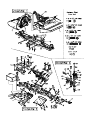
REMOVE OLD CHASSIS
1. (Diagram 2) Remove the four 4-40x5/16" screws (B) from the front
bumper (2).
2. (Diagram 2) Remove the two rear 2.5mm e-clips (S) using a small flat
blade screwdriver from the inner front hinge pins (104). Pull on the front
hinge pin brace (50) to remove the two inner front hinge pins (104). Be
careful not to loose the e-clips.
3. (Diagram 2) Loosen the 3mm set screw (K) from the bulkhead (51).
Remove the bulkhead/chassis hinge pin (103).
4. (Diagram 2) Remove the four 4-40x3/4" screws (E) from the upper
plate (52). Rotate the front assembly out of the way.
5. (Diagram 2) Remove the two 4-40x3/8" screws (C) from the servo
brace (56) and set them aside.
6. (Diagram 2) Remove the two 4-40x5/16" screws (B) located on the
bottom of the chassis that hold the servo mounts (6) to the chassis. Lift
the servo saver assembly off at the same time as the servo.
7. Unplug the speed control from the receiver and remove the receiver
from the chassis with the steering servo still plugged in. This will help
during the re-assembly process.
8. (Diagram 2) Carefully pry out the two brass bushing (105) from the
front of the chassis (1) using a hex wrench included with the kit.
9. Disconnect the motor leads from the speed control and remove the
speed control from the rear shock tower (40).
10. (Diagram 1) Remove the four 4-40x1/2" screws (D) from the rear
shock tower (40).
11. (Diagram 1) Remove the four 4-40x3/8" screws (C) from the rear
chassis plate (41).
The chassis (1) should be free from all other parts at this point.
INSTALL NEW CHASSIS
1. (Diagram 1) Slide the rear chassis plate (41) and the chassis (1)
together and re-install the four 4-40x3/8" screws (C).
2. (Diagram 1) Attach the rear shock tower (40) to the chassis (1), using
the four 4-40x1/2" screws (D). The screws should pass through the rear
shock tower (40), chassis (1) and thread into the transmission brace (42).
3. (Diagram 2) Install the two brass bushings (105) into the chassis.
4. (Diagram 2) Connect the chassis (1) with the front bulkhead (51) and
install the bulkhead/chassis hinge pin (103) and tighten the 3mm set
screw (K).
5. Install the steering servo into the chassis with the two 4-40x5/16"
screws (B). Note: There are two sets of holes in the bottom of the servo
mounts (6).Make sure you install the screws into the same hole they came
out of. (Refer to page 9 of the instruction manual included with the kit).
6. Install the servo saver assembly onto the chassis.
7. (Diagram 2) Install the servo brace (56) onto the chassis using the two
4-40x3/8" screws (C).
8. (Diagram 2 & 3) Rotate the upper plate (52) onto the chassis. Make sure
the metal pins (99 & 100) of the servo saver assembly are properly seated
into the brass bushings (105) located in both the chassis and the upper plate.
Attach the upper plate to the chassis using the four 4-40x3/4" screws (E).
9. (Diagram 2) Re-install the front suspension arms (38 & 39) to the front
bulkhead using the inner hinge pins (104) and the front hinge pin brace
(50). Secure the hinge pins by installing the two 2.5mm e-clips (S) onto
the ends of the two hinge pins (104).
10. (Diagram 2) Attach the front bumper (2) using the four 4-40x5/16"
screws (B).
11. Install the receiver to the chassis. You can try to remove double-sided
foam block used on the old chassis or use several layers of new (not
included) double-sided foam tape to obtain the same elevation so that the
receiver will clear the rails on the chassis. DO NOT cut the rails on the
chassis for the receiver to fit, as this will drastically weaken the chassis.
12. Install the electronic speed control to the rear shock tower using
double-sided foam tape. Re-connect the servo lead to the receiver and
the motor leads to the motor wires.
REMOVE OLD BULKHEAD
(Refer to Diagram 2)
1. Remove the four 4-40x5/16" screws (B) from the front bumper (2) and
set them aside.
2. Remove the two rear 2.5mm e-clips (S) using a small flat blade
screwdriver from the inner hinge pins (104). Pull on the front hinge pin
brace (50) to remove the two inner hinge pins (104).
3. Loosen the 3mm set screw (K) from the under side of the bulkhead
(51). Remove the bulkhead/chassis hinge pin (103).
4. Remove the four 4-40x3/8" screws (C) that attach the front shock tower
(49) to the front bulkhead (51) and rotate the shock tower out of the way.
5. Remove the two 4-40x5/16" screws (B) that attach the upper plate to
the front bulkhead.
The front bulkhead should be free from all of the other parts at this point.
INSTALL NEW BULKHEAD
(Refer to Diagram 2)
1. Connect the front bulkhead (51) to the chassis (1) and install the
bulkhead/chassis hinge pin (103) and tighten the 3mm set screw (K).
2. Re-install the two 4-40x5/16" (B) screws through the upper plate (52)
and into the bulkhead (51).
3. Use the four 4-40x3/8"screws (C) to re-attach the front shock tower
(49) to the bulkhead (51).
FRONT BULKHEAD REPLACEMENT
CHASSIS REPLACEMENT
DETAILED ASSEMBLY GUIDE
USE THIS GUIDE ALONG WITH YOUR MANUAL.
REFER TO THE APPROPRIATE SECTION THAT PERTAINS
TO YOUR REPLACEMENT PART

4. Re-install the front suspension arms (38 & 39) to the front bulkhead
using the inner hinge pins (104) and the front hinge pin brace (50).
Secure the hinge pins by re-installing the two 2.5mm e-clips (S) onto the
ends of the two hinge pins (104).
5. Attach the front bumper (2) using the four 4-40x5/16" (B) screws.
REMOVE OLD SUSPENSION ARM
(Refer to Diagram 2)
1. Remove the four 4-40x5/16" screws (B) from the front bumper (2) and
set them aside.
2. Remove the front suspension arm (38 or 39) by removing the rear
2.5mm e-clip (S) from the inner front hinge pin (104).Slide the inner front
hinge pin out of the bulkhead and suspension arm.
3. Remove the 4-40x1/2" screw (D) that attach the bottom of the shock
to the front suspension arm. Rotate the shock out of the way.
4. Remove the front wheel.
5. Remove the two 2mm e-clip (R) from the front of the outer hinge pin
(95) and slide the outer hinge pin out.
The front suspension arm should be free from all of the other parts
at this point.
INSTALL THE NEW FRONT SUSPENSION ARM
(Refer to Diagram 2)
1. Install the front suspension arms (38 or 39) to the front bulkhead (51)
using the inner hinge pin (104). Secure the hinge pin by re-installing the
2.5mm e-clip (S) onto the end of the hinge pin (104).
2. Re-attach the front bumper (2) using the four 4-40x5/16" screws (B).
3. Attach the shock to the new suspension arm (38 or 39) by installing
the 4-40x1/2" screw (D).
4. Insert the outer hinge pin (95) through the front suspension arm and
front hub carrier (28). Secure the hinge pin by re-installing the 2mm
e-clip (R).
5. Re-install the front wheel and secure it using the 3/16" nuts (M).
REMOVE OLD UPPER PLATE AND SERVO BRACE
(Refer to Diagram 2)
1. Loosen the four 4-40x3/8"screws (C) in the front shock tower (49)
two turns.
2. Remove the four 4-40x3/4" screws (E) and the two 4-40x1/4" (B)
screws and remove the upper plate (52) leaving the servo saver
assembly in place.
3. Remove the two brass bushing (105) from the upper plate (52) using
a hex wrench included with the kit to pry them out.
4. Remove the two 4-40x3/8" screws (C) and remove the servo brace (56).
INSTALL THE NEW UPPER PLATE AND SERVO BRACE
(Refer to Diagram 2)
1. Install the new servo brace (56) using the two 4-40x3/8" screws (C).
2. Install the two brass bushings (105) into the new upper plate (52)
3. Install the new upper plate using the four 4-40x3/4" screws (E) and
two 4-40x1/4" screws (B).
4. Tighten the four 4-40x3/8 screws (C) in the front shock tower (49).
REMOVE THE OLD CHASSIS PLATE
(Refer to Diagram 1)
1. Remove the two 2.5mm e-clips (S) using a flat blade screwdriver from
the inner rear hinge pins (97) then, remove the hinge pins.
2. Remove the two 4-40x1/4" screws (A) to detach the rear chassis plate
(41) from the motor guard (3).
3. Remove the two 4-40x3/8" screws (C) that remove the rear chassis
plate (41) to the gearbox.
4. Remove the four 4-40x3/8" screws (C) to remove the rear chassis
plate (41) from the chassis (1).
The rear chassis plate should be free from all other parts at this point.
INSTALL NEW REAR CHASSIS PLATE
(Refer to Diagram 1)
1. Attach the new rear chassis plate (41) to the chassis (1) using the four
4-40x3/8" screws (C).
2. Install the two 4-40x3/8" screws (C) to secure the gearbox to the main
chassis plate (41).
3. Install the two 4-40x5/16" (B) screws that attach the rear chassis plate
(41) to the motor guard (3).
4. Attach the rear suspension arms (36 & 37) to the rear chassis plate
(41) using the two inner rear hinge pins (97). Secure the hinge pins by
re-installing the two 2.5mm e-clips (S) onto the hinge pins. Hint: First
position the e-clips in the grooves of the hinge pins using your
finger.Then, use a flat blade screwdriver to push the e-clip in place.
REAR CHASSIS PLATE REPLACEMENT
UPPER PLATE & SERVO BRACE REPLACEMENT
FRONT SUSPENSION ARM REPLACEMENT

-
 1
1
-
 2
2
-
 3
3


Ask a question and I''ll find the answer in the document
Finding information in a document is now easier with AI
Related papers
-
Duratrax Evader ST Pro Prebuilt User manual
-
Duratrax Evader BX User manual
-
-
-
-
-
-
-
-
Other documents
-
Associated Electrics RC10 B44.2 User manual
-
-
-
-
-
-
-
AE RC10TC6 Assembly Manual
-
Losi LOSA1754 Installation guide
-
 Cen GST 7.7 User manual
