
8/11

2
:: Introduction
:: KIT Features
:: Additional Features
:: Other Helpful Items
Associated Electrics, Inc.
26021 Commercentre Dr.
Lake Forest, CA 92630
http://www.TeamAssociated.com · http://www.RC10.com · http://twitter.com/Team_Associated · http://bit.ly/AEonFacebook
Customer Service
Tel: 949.544.7500
Fax: 949.544.7501
Thank you for purchasing this Team Associated product. This assembly manual contains instructions and tips for building and
maintaining your new RC10TC6. Please take a moment to read through this manual to help familiarize yourself with these steps.
We are continually changing and improving our designs; therefore, actual parts may appear slightly different than in the illustra-
tions. New parts will be noted on supplementary sheets located in the appropriate parts bags. Check each bag for these sheets
before you start to build.
Team Associated Factory Team TC6 is Area-51’s next generation touring car. Based off decades of race experience with its roots
heavily planted from the bar setting TC3, the TC6 blends the best of performance and adjustability to compete in today’s touring
car racing class. The updated chassis platform considers many hours of testing from Factory Team drivers over the last few race
seasons, keeping focus strictly on brushless motors and LiPo batteries. The resulting layout is optimized for the speeds and grip
levels that are now higher than ever before… the RC10TC6-FT is definitely another Champion by Design from Team Associated!
• Chassis layout optimized for Lithium Batteries and Brushless Motors
o Motor moved toward chassis center by 13mm from TC5
o Ultra narrow LiPo chassis with two battery positions, forward and back
o Servo mounting slots to ensure proper fit of any servo
o Spur gear lowered by 5mm from TC5
o Lengthened top plate with symmetric mounting points for equal flex
o Motor mounts to centralized point in chassis for equal flex
• Common bulkhead layout minimizes spare part cost
• Updated steering system
o More Ackermann options (16 positions total) to fine tune steering feel
o Improved steering input rate for more consistent handling
• VCS3 Shock with hard anodized threaded shock bodies
o Bottom loading seal system for ease of build
o TiN coated shock shaft
o Piston attaches to shock shaft with screw for tight clamping and no slop
o Improved bladder for more consistent build through time
o Threaded collar with fine pitch thread for ease of accurate ride height adjustment
o Increased stroke for more up-travel at wheel
• Long upper link option for increased corner speed
• Hard anodized diff outdrives for low wear and long life
• Cross-compatibility with TC5 suspension components
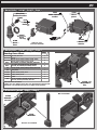
Your new TC6 comes unassembled and requires the following items for completion.
(refer to catalog section for suggestions):
• 1:10th scale electric motor and electronic speed control
• 3.7V-7.4V LiPo, 6.0V LiFe, or 4.8V-7.2V NiMh
• Battery charger (suited for, and particular to, one of the batteries mentioned above)
• 2 channel surface transmitter, 2 channel receiver, and steering servo
• 1:10th scale lexan touring car body
• Lexan specific spray paint for body
• 1:10th scale rubber (or foam) touring car tires
• Silicone Shock Fluid (Refer to catalog for complete listings)
• Body Scissors (AE Part # 1737) • Reamer / Hole Punch
• FT Hex Wrenches (AE Part # 1541) • Hobby Knife
• Needle Nose Pliers • Wire Cutters • Multi Tool (AE Part #7494)
• Soldering Iron
• Calipers or a Precision Ruler

3
:: Table of Contents
:: Notes
This symbols indicates a
special note or instruction
in the manual.
!
There is a 1:1 hardware foldout page in the back
of the manual. To check the size of a part, line
up your hardare with the correct drawing until
you find the exact size. Each part in the foldout
has a number assigned to it for ordering
replacement parts.
1....................Cover
2....................Introduction
3....................Table of Contents
4-5................Shock Build (Bag A-AA)
5-6...............Front Slipper Spool Build
(Bag B-BB)
6-8...............Rear Differential Build
(Bag B-BB)
8....................CVA Axle Build (Bag C)
9....................Turnbuckle Build (Bag D)
9....................Front Bulkhead Build (Bag E-EE)
10.................Rear Bulkhead Build (Bag E-EE)
10.................Spur Gear Bulkhead / Motor
Mount Install (Bag E-EE)
11.................Shock Tower Build (Bag E-EE)
11-12..........Steering Bellcrank Build /
Install (Bag F)
12.................Spur Gear Shaft Build
(Bag G-GG)
13.................Spur Gear Hub / Belt Install
(Bag G-GG)
13-14..........Front Slipper Spool Install
(Bag G-GG)
14.................Rear Differential Install
(Bag G-GG)
14.................Top Plate / Bearing Caps
Install (Bag G-GG)
15-16..........Steering Block Build / Install
(Bag H)
17.................Rear Hubs Build / Install (Bag H)
18.................Shocks Install (Bag I)
18.................Bumper Build / Install (Bag I)
19.................Pivoting Body Mounts Install
(Bag I)
19.................Battery Braces / Antenna
Mount Install (Bag I)
20.................Anti-Roll Bars Build / Install
(Bag J)
21.................Servo Build / Install (Bag K)
21-22.........Electronics Install (Bag L)
22.................Wheels / Tires Build / Install
(Bag L)
23-25.........Tuning Tips
26-33.........Catalog
34.................Notes
35.................Setup Sheet “Kit Setup”
36.................1:1 Hardware “Fold Out”
37.................Setup Sheet “Blank”
38.................Back Cover
Associated Electrics, Inc.
26021 Commercentre Dr.
Lake Forest, CA 92630
http://www.TeamAssociated.com · http://www.RC10.com · http://twitter.com/Team_Associated · http://bit.ly/AEonFacebook
Customer Service
Tel: 949.544.7500
Fax: 949.544.7501

4
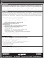
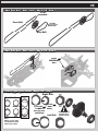
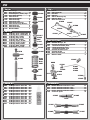
:: Shock Build - Bag A-AA - Step 1
:: Shock Build - Bag A-AA - Step 2
:: Shock Build - Bag A-AA - Step - 3
31325
VCS3 shock
body
6465
Shock
piston
(#3)
31330
VCS3 shock
shaft
31249
Shock shaft
ball cup
5407
Red
o-rings
31324
VCS3
o-ring
spacer
31324
Shock
bladder
Bladder Installation
With the shaft fully extended, place
bladder on the top of the shock body,
displacing the extra oil. While
maintaining pressure on the bladder
against the shock body, carefully lift
one side of the bladder to allow any
extra oil to escape. Place stock cap
on top of bladder, and secure it by
threading the aluminum cap retainer
onto the shock body.
31329
VCS3 shock
cap
31326
VCS3 shock
ccollar o-ring
31326
VCS3
shock collar
31327
VCS3 shock
bottom cap
31327
VCS3 shock
bottom cap
o-ring
31510
M2x4mm
bhcs
31324
Hat
bushing
31328
VCS3
Aluminum
cap retainer
31324
VCS3
piston
bushing
VCS3 shock
VCS3 shock
31249
Shock shaft
ball cup
Shock oil
(40wt)
Shock oil
(40wt)
Shock oil
(40wt)
#1596
thread lock

5
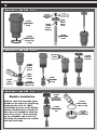
:: Shock Build - Bag A-AA - Step 4
:: Front Slipper Spool Build - Bag B-BB - Step 1
:: Front Slipper Spool Build - Bag B-BB - Step 2
31169
Diff pulley
flange
31173
Slipper
spool
pads
31338
TC6 diff
outdrives
(short)
31338
TC6 diff
outdrives
(long)
31173
Slipper
spool
pads
31169
Diff pulley
(40T)
6573
Diff thrust
washer
6574
5/64” diff
thrust balls
6573
Diff thrust
bolt
x2
x6
x2
3942
Silver
spring
(front)
3941
Green
spring
(rear)
6475
Shock
spring cup
31400
5x8mm
bearing
Build four
shocks
31338
TC6 diff
outdrives
spring cup
Diff thrust
#1597
ca glue
#6588
black grease
!

6
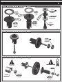
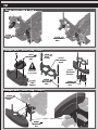
:: Front Slipper Spool Build - Bag B-BB - Step 3
:: Front Slipper Spool Build - Bag B-BB - Step 4
:: Rear Differential Build - Bag B-BB - Step 1
Pre-compress spring
!
Press nut all
the way in!
!
3904
2-56 mini
locknut
x2
x2
31401
10x15mm
bearing
31162
Shim
31166
Diff T-nut
6582
Diff thrust
spring
31166
Washer
31169
Diff pulley
flange
31169
Diff pulley
(40T)
6581
3/32”
carbide diff
balls
x12
#1597
ca glue
#1596
thread lock
#6591
diff lube
Fully tighten thrust screw
for slipper spool!
Recheck screw tightness
after initial run!!!
Recheck screw
periodically!
!
!

7
:: Rear Differential Build - Bag B-BB - Step 2
:: Rear Differential Build - Bag B-BB - Step 3
:: Rear Differential Build - Bag B-BB - Step 4
Pre-compress spring
!
Press nut all
the way in!
!
3904
2-56 mini
locknut
31166
Diff T-nut
x231400
5x8mm
bearing
6573
Diff thrust
washer
6574
5/64” diff
thrust balls
6573
Diff thrust
bolt
x2
x6
Diff thrust
Pre-compress spring
!
2-56 mini
locknut
31338
TC6 diff
outdrives
(short)
31338
TC6 diff
outdrives
(long)
3906
D-drive
ring
3906
D-drive
ring
6582
Diff thrust
spring
31166
Washer
#6591
diff lube
#6588
black grease
#6591
diff lube

8
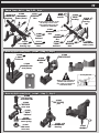
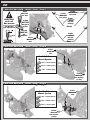
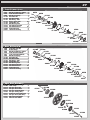
:: Rear Differential Build - Bag B-BB - Step 5
:: CVA Axle Build - Bag C - Step 1
:: CVA Axle Build - Bag C - Step 2
-1/8
-5/8
-1/4
-3/8
0
-1/4 -3/4
Diff Setting:
Tighten thrust screw until
spring is fully compressed.
Then loosen 1/8 turn
(see diagram).
Re-check after initial run.
5/64” hex wrench
installed in diff bolt
Kit
Setting
Diff Setting:
Tighten thrust screw until
spring is fully compressed.
x2
x2
31401
10x15mm
bearing
31162
Shim
31227
CVA
coupler
31227
CVA
cross pin
31232
CVA
bones
31238
CVA blade
31231
CVA axle
31237
retaining
clip
Build four
CVA’s
Note!
Align the gap in
the pin retainer to
be opposite of the
CVA pin.
#6588
black grease
!!

9
:: Turnbuckle Build - Bag D - Step 1
:: Front Bulkhead Build - Bag E-EE - Step 1
:: Front Bulkhead Build - Bag E-EE - Step 2
Servo Turnbuckle
Steering Turnbuckle
Camber Turnbuckle
Wheel Base Shims
1mm
2mm
1º 1.5º 2º
Arm Mount Shims
29.55mm
x4
x2
x2
x2
25187
M3x14mm
bhcs
31309
TC6
bulkhead
31280
5mm
ballstud
31221
Inner
hinge pin
31200
Wheelbase
shim (2mm)
31200
Wheelbase
shim (1mm)
25227
M4x8mm
setscrew
31203
Front
suspension
arm (HARD)
31198
Arm mount
shim (2˚)
31540
M3x5mm
fhcs
31300
TC6
chassis
1418
0.825”
turnbuckle
1403
1.65”
turnbuckle
1405
1.875”
turnbuckle
x2
x2
x2
x2
x4
x4
51.50m
56.50mm
x2
51.10m
x2 x2
31305
Turnbuckle
eyelet
shim (2mm)
x4
x4
31321
TC6 arm
mount
(2 dot)
31322
TC6 arm
mount
bushing
Arm Mounts
Roll Center
Low High
0 1 2 3
Front Rear
Refer to page 24
for droop
settings!
!

10
:: Rear Bulkhead Build - Bag E-EE - Step 1
:: Rear Bulkhead Build - Bag E-EE - Step 2
:: Spur Gear Bulkhead / Motor Mount Install - Bag E-EE - Step 1
Wheel Base Shims
1mm
2mm
1º 1.5º 2º
Arm Mount Shims
x231221
Inner
hinge pin
25227
M4x8mm
setscrew
x2
x4
x4
31321
TC6 arm
mount
(2 dot)
31322
TC6 arm
mount
bushing
x231280
5mm
ballstud
31200
Wheelbase
shim (2mm)
31204
Rear
suspension
arm (HARD)
x2
x2
x2
1º
1.5º
2º
Arm Mount Shims
x231198
Arm mount
shim (1.5˚)
31198
Arm mount
shim (2˚)
25187
M3x14mm
bhcs
31312
TC6 motor
mount
31313
TC6 motor
mount brace
31540
M3x5mm
fhcs
31311
TC6
spur gear
bulkhead
31532
M3x8mm
bhcs
31540
M3x5mm
fhcs
31531
M3x6mm
bhcs
x4
x4
x4
x2
x2
31540
M3x5mm
fhcs
x4
31200
Wheelbase
shim (1mm)
Arm Mounts
Roll Center
Low High
0 1 2 3
x231309
TC6
bulkhead
Refer to page 24
for droop
settings!
!

11
:: Shock Tower Build - Bag E-EE - Step 1
:: Steering Bellcrank Build / Install - Bag F - Step 1
:: Steering Bellcrank Build / Install - Bag F - Step 2
Steering Bellcrank
7
8
A B C
x2
x2
x2
x2
x4
x2
31310
TC6
bearing cap
2230
Body
mounts
31531
M3x6mm
bhcs
31281
8mm
ballstud
31532
M3x8mm
bhcs
31541
M3x6mm
fhcs
31532
M3x8mm
bhcs
31302
TC6 shock
tower (front)
31303
TC6 shock
tower (rear)
31531
M3x6mm
bhcs
31281
8mm
ballstud
31280
5mm
ballstud
31308
TC6 bellcrank
arm (7mm)
31308
TC6 bellcrank
31541
M3x6mm
fhcs
31250
Shock
bushing
x2
x2
x2
x4
x2
x231250
Shock
bushing
x231310
TC6
bearing
cap
31403
4x7mm
bearing
31307
TC6 steering
post
31306
TC6 steering
bellcrank tube
31280
5mm
ballstud
31308
TC6 servo
saver arm
31306
TC6 servo
saver spring
31306
TC6 servo
saver nut
x2
31307
C-clip
Align steering bellcrank to
position B for initial set-
ting. Refer to page 23 for
Ackermann chart.
Do not tighten #31541 screws
all the way! Leave screws
loose until bearing caps are
attached to bulkheads!
!
!

12
:: Steering Bellcrank Build / Install - Bag F - Step 3
:: Spur Gear Shaft Build - Bag G-GG - Step 1
:: Spur Gear Shaft Build - Bag G-GG - Step 2
31333
TC6
spur gear
(87T / 48P)
31530
M3x5mm
bhcs
31315
TC6 spur
gear shaft
31320
TC6 spur
pulley
(20T)
31314
TC6 spur
gear hub
31319
TC6 spur gear
clamping ring
31308
TC6 steering
bellcrank
post insert
x3
x2
31308
TC6 steering
bellcrank
post insert
x2
x2
31331
4x8x3
flanged
bearing
31160
3mm
e-clip
Use rear hole for
standard position!
Refer to page 23 for
Ackermann chart
!
0.5mm
Servo Saver
Adjustment
TC6 spur
flanged
bearing

13
:: Spur Gear Hub / Belts Install - Bag G-GG - Step 1
:: Spur Gear Hub / Belts Install - Bag G-GG - Step 2
:: Front Slipper Spool Install - Bag G-GG - Step 1
Right Side
Front Belt
Rear Belt
Left Side
Cam Position
Mid-Low
Mid-High
Low
High
Note!
Always use the same
cam position on both
sides of the vehicle.
31184
Cam
holder
31185
Diff
bearing cam
(mid-high)
31187
Front belt
31188
Rear belt
x2
x2
x231521
M2.5x8mm
bhcs
Belt Tension
Number
View from left
side of car
17 32
161
Use belt tension
position 28 for
standard setup.
!

14
:: Front Slipper Spool Install - Step 2 / Rear Differential Install - Bag G-GG - Step 1
:: Rear Differential Install - Bag G-GG - Step 2
:: Top Plate / Bearing Caps Install - Bag G-GG - Step 1
Right Side
Left Side
x8
x3
x4
x4
31540
M3x5mm
fhcs
31530
M3x5mm
bhcs
31531
M3x6mm
bhcs
31531
M3x6mm
bhcs
31301
TC6 top
plate
31184
Cam
holder
31185
Diff
bearing cam
(mid-low)
x2
x2
Slide belt over
diff pulley!
!
Slide belt over
diff pulley!
!
Note!
Place top
plate between
the front belt.
Tighten #31531 screws.
Then tighten #31541
shock tower screws!
! !
Belt Tension
Number
View from left
side of car
17 32
161
Use belt tension
position 6 for
standard setup.
!

15
:: Steering Block Build / Install - Bag H - Step 1
:: Steering Block Build / Install - Bag H - Step 2
:: Steering Block Build / Install - Bag H - Step 3
Note side view
!
31532
M3x8mm
bhcs
31281
8mm
ballstud
x2
x2
31404
6x10mm
bearing
31286
Aluminum
ballstud
washer
(1mm)
x4
x2
31280
5mm
ballstud
31233
Axle crush
tube
x2
x2
x231561
Steering
blocks
(HARD)
31557
Caster block
4 deg
(HARD)
x2
31214
Caster
block
bushing
x4

16
:: Steering Block Build / Install - Bag H - Step 4
:: Steering Block Build / Install - Bag H - Step 5
:: Steering Block Build / Install - Bag H - Step 6
31162
Axle shim
31234
Clamping
wheel hex
31511
M2x5mm
shcs
31112
1/16” x 5/16”
dowel pins
x2
x2
x2
x2
x2
x2
31510
M2x4mm
bhcs
31222
Outer
hinge pin
It is important that the turnbuckle eyelets fit freely
over the ball studs after they are snapped on. If the
fit is too tight, car handling will be inconsistent. Check
the fit by grabbing onto the installed turnbuckle with
your fingers and twisting it so that the turnbuckle eye-
lets pivot on the ball studs. The turnbuckle should twist
freely with no resistance. If there is resistance, the fit
is too tight. The turnbuckle eyelet fit can be loosened
by squeezing it with a needle-nose pliers, as shown in
the photo below. It is important that a ball stud be
snapped into the turnbuckle eyelet before squeezing!
Be sure to check and adjust the fit for each end of all
the links that are added to the chassis.
!

17
:: Rear Hubs Build / Install - Bag H - Step 1
:: Rear Hubs Build / Install - Bag H - Step 2
:: Rear Hubs Build / Install - Bag H - Step 3
31162
Axle shim
31562
Rear hub
(0 deg)
(HARD)
31234
Clamping
wheel hex
31511
M2x5mm
shcs
31112
1/16” x 5/16”
dowel pins
x2
x2
x2
x2
x2
x2
x2
31510
M2x4mm
bhcs
31222
Outer
hinge pin
31404
6x10mm
bearing
31286
Aluminum
ballstud
washer
(2mm)
x4
x2
31233
Axle crush
tube
x2
31281
8mm
ballstud
x2

18
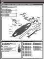
:: Shocks Install - Bag H - Step 1
:: Bumper Build / Install - Bag I - Step 1
:: Bumper Build / Install - Bag I - Step 2
Transponder
and screws
not included!
25201
M3x8mm
fhcs
2230
Body
mounts
31316
TC6 bumper
brace
31316
TC6
bumper
4673
M2.5x4mm
bhcs
x2
x2
x3
x2
x2
x3
x2
31530
M3x5mm
bhcs
25202
M3x10mm
fhcs
25203
M3x12mm
fhcs
31317
TC6 foam
bumper
31530
M3x5mm
bhcs
x231530
M3x5mm
bhcs
!

19
:: Pivoting Body Mounts Install - Bag I - Step 1
:: Battery Braces / Antenna Mount Install - Bag I - Step 1
:: Battery Braces / Antenna Mount Install - Bag I - Step 2
31530
M3x5mm
bhcs
31318
TC6 lipo
battery
brace (fr/rr)
31541
M3x6mm
fhcs
31541
M3x6mm
fhcs
31541
M3x6mm
fhcs
31318
Antenna
mount
31318
TC6 inner
lipo brace
3897
Pivoting
body mounts
1736
FT body
clips (blue)
x2
x2
x2
x4
x2
x2
x2
x2
x2
31304
TC6 battery
tape tab
3897
Pivoting
body mounts
1736
FT body
clips (blue)
Use forward position for
standard setup. Refer to page
24 for explanation of battery
position tuning options!
!

20
:: Anti-Roll Bars Build / Install - Bag J - Step 1
:: Anti-Roll Bars Build / Install - Bag J - Step 2
:: Anti-Roll Bars Build / Install - Bag J - Step 3
Front
Rear
Anti-Roll Bar
Mount System
1 dot: 1.25mm (black)
2 dot: 1.50mm (silver)
3 dot: 1.75mm (gold)
Anti-Roll Bar
Mount System
1 dot: 1.25mm (black)
2 dot: 1.50mm (silver)
3 dot: 1.75mm (gold)
31264
Anti roll
bar mounts
(1 dot)
31511
M2x5mm
shcs
31269
Anti roll
bar pivot
31261
1.25mm
roll bar
(black)
31261
1.25mm
roll bar
(black)
8828
Anti roll
bar cups
31269
Anti roll
bar pivot
mount
31058
Anti roll
bar
ballstud
x2
x2
x2
x2
x2
31511
M2x5mm
shcs
31264
Anti roll
bar mounts
(1 dot)
31511
M2x5mm
shcs
31500
M3x2.5mm
set screw
Build four
anti-roll
bar mounts
!
16.5mm
Anti Roll Bar
Link Adjust
ment
16.5mm
Page is loading ...
Page is loading ...
Page is loading ...
Page is loading ...
Page is loading ...
Page is loading ...
Page is loading ...
Page is loading ...
Page is loading ...
Page is loading ...
Page is loading ...
Page is loading ...
Page is loading ...
Page is loading ...
Page is loading ...
Page is loading ...
Page is loading ...
Page is loading ...
-
 1
1
-
 2
2
-
 3
3
-
 4
4
-
 5
5
-
 6
6
-
 7
7
-
 8
8
-
 9
9
-
 10
10
-
 11
11
-
 12
12
-
 13
13
-
 14
14
-
 15
15
-
 16
16
-
 17
17
-
 18
18
-
 19
19
-
 20
20
-
 21
21
-
 22
22
-
 23
23
-
 24
24
-
 25
25
-
 26
26
-
 27
27
-
 28
28
-
 29
29
-
 30
30
-
 31
31
-
 32
32
-
 33
33
-
 34
34
-
 35
35
-
 36
36
-
 37
37
-
 38
38


Ask a question and I''ll find the answer in the document
Finding information in a document is now easier with AI
Related papers
-
AE TEAM ASSOCIATED RC10T4 TRUCK User manual
-
-
Associated Electrics RC10SC5M User manual
-
-
-
-
Associated Electrics B5M User manual
-
AE B44.1 Assembly Manual
-
-
Other documents
-
Summit Appliance WLM610P Installation guide
-
Kyosho No.IGW053 3D Bumper for GT2 User manual
-
-
Losi LOSA1759 Operating instructions
-
-
-
CableWholesale 30W1-00200 Datasheet
-
LRP 80749 Datasheet
-
Gorilla Carts GCT-10NF Operating instructions
-