Page is loading ...

3/13

2
:: Introduction
:: KIT Features
:: Additional
:: Other Helpful Items
Associated Electrics, Inc.
26021 Commercentre Dr.
Lake Forest, CA 92630
http://www.TeamAssociated.com · http://www.RC10.com · http://twitter.com/Team_Associated · http://bit.ly/AEonFacebook
Customer Service
Tel: 949.544.7500
Fax: 949.544.7501
Thank you for purchasing this Team Associated product. This assembly manual contains instructions and tips for building and
maintaining your new RC10 T4.2. Please take a moment to read through this manual to help familiarize yourself with these steps.
We are continually changing and improving our designs; therefore, actual parts may appear slightly different than in the
illustrations. New parts will be noted on supplementary sheets located in the appropriate parts bags. Check each bag for these
sheets before you start to build.
Features in the T4.2 Factory Team:
• Factory Team 12mm “Big Bore” hard anodized, threaded aluminum shocks with TiN “Gold” 3mm shock shafts
• VTS slipper (variable torque, multi-plate slipper with 3 drive surfaces) and high-resolution spring
• Factory Team blue aluminum steering bellcrank set
• Factory Team 12mm blue aluminum front and rear clamping hexes with hex drive wheels
• “Gull-wing” front suspension arms and updated front and rear shock towers optimized for12mm big bore shocks
• Factory Team 7075-T6 blue aluminum 0° rear hubs with oversized outer bearing
• Pro-Line Bulldog body
• CVA joints with pin retainer clips
• Ball differential with light-weight outdrives
• Factory Team carbon fiber battery strap and blue aluminum thumb screws
• Complete set of precision ball bearings
• Factory Team blue titanium turnbuckles, blue aluminum hinge pin brace, milled motor plate, servo mounts, rear ballast weight
and much more!
Your new T4.2 FT kit comes unassembled
and requires the following items for completion
(refer to catalog section for suggestions):
• R/C two channel surface frequency radio system
• AA-size batteries for transmitter
(#302 alkaline, #303 rechargealble)
• Electronic Speed Control, ESC (#29140, #29143)
• Steering servo (#29166, #29167) • R/C electric motor
• Pinion gear, size determined by type/wind of motor
• Battery charger (a peak detection charger, or LiPo compatible charger)
• 6 cell NiMH battery pack (#700) or a 2 cell LiPo battery pack (#714)
• Calipers or a precision ruler • Needle nose pliers
• Lexan specific spray paint
• Reamer / hole punch
• Cyanacrylate glue (#1597)
• Thread locking compound (#1596)
• Tires and Inserts, Fronts and Rears
Tools included:
• Allen wrenches #6950 (.050”, 1/16”, 3/32”, 5/64”)
• Molded tools #6956
• Camber gauge #1719
• Silicone Shock Fluid (Refer to catalog for complete listings)
• Body Scissors (AE Part # 1737) • Reamer / Hole Punch • Wire Cutters • Hobby Knife
• FT Hex Wrenches (AE Part # 1655) • Needle Nose Pliers • Multi Tool (AE Part #7494)
• Soldering Iron • Calipers or a Precision Ruler • Green Slime shock lube (AE Part # 1105)

3
:: Table of Contents
:: Notes
This symbols indicates a
special note or instruction
in the manual.
!
There is a 1:1 hardware foldout page in the back
of the manual. To check the size of a part, line
up your hardare with the correct drawing until
you find the exact size. Each part in the foldout
has a number assigned to it for ordering
replacement parts.
1................... Cover
2................... Introduction
3................... Table of Contents
4................... Steering Build
(Bag A-AA)
4 - 5............. Front End, Outer Build
(Bag B-BB)
5 - 6............. Front End, Inner Build
(Bag C)
6 - 9............. Transmission Build
(Bag D-DD)
9 - 11........... Rear End Build
(Bag E-EE)
11 - 12........ CVA and Turnbuckle Build
(Bag F-FF)
12 - 14........ Shocks Build
(Bag G-GG)
14 - 16........ Electronics Build
(Bag H-HH)
16 - 17........ Wheels, Tires and Body Install
(Bag I)
17................. Servo Chart
18 - 19....... Tuning Tips
20 - 29....... Catalog
30................ Notes
31................ Setup Sheet “Kit Setup”
32................ 1:1 Hardware “Fold Out”
33................ Setup Sheet “Blank”
34................ Back Cover
Associated Electrics, Inc.
26021 Commercentre Dr.
Lake Forest, CA 92630
http://www.TeamAssociated.com · http://www.RC10.com · http://twitter.com/Team_Associated · http://bit.ly/AEonFacebook
Customer Service
Tel: 949.544.7500
Fax: 949.544.7501

:: Steering Build - Bag A-AA - Step 2
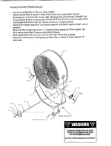
:: Front End, Outer Build - Bag B-BB - Step 1
4
:: Steering Build - Bag A-AA - Step 1
Install the C Clip
into the groove
shown below.
Do not overtighten steering bolts. Make sure
there is free movement in the steering rack.
!
!
Build 2 (1 left, 1 right) Build 2!
!
9659
Steering
brace
9640
Steering
bolt
(left)
6272
Dust cover
foam
9647
Block carrier
bushing
x2
x2
x2
x2
3981
Ballstud, .20
black, short
6276
Ballstud, .20
silver, short
6917
4-40x3/8
bhcs
6272
Dust cover
foam
9679
FT Aluminum
Bellcrank Set
3971
Steering rack
bearing
9566
Top plate
9640
Steering
bolt
(right)
9659
Steering
rack
x4
Be careful to not get
thread lock on steering
rack bushings!
!
!
!
6272
Dust cover
foam
31286
FT ballstud
washer,
aluminum
(2mm)
9880
Steering
block, hex
6277
Ballstud, .30
silver, long
4449
4-40x3/16
aluminum
locknut
#1596
thread lock
6922
4-40x1/2
fhcs
6915
4-40x5/8
fhcs
7440
T4 chassis
89229
Blue
countersunk
washer
9563
Front
bulkhead
x3
x3
x2
7854
T4 front
axle, hex
3977
3/16x3/8
bearing
9882
C-clip, 3/16

5
:: Front End, Outer Build - Bag B-BB - Step 2
:: Front End, Outer Build - Bag B-BB - Step 3
:: Front End, Inner Build - Bag C - Step 1
6272
Dust cover
foam
Align the C-clip on
the front axles
with the D-shape
inside the
steering blocks.
!
7922
Caster block,
30°
(1 left, 1 right)
3983
Ballstud, .30
black, short
4449
4-40x3/16
aluminum
locknut
foam
with the D-shape
steering blocks.
3977
3/16x3/8
bearing
9898
2-56x3/16
shcs
9892
12mm aluminum
clamping wheel
hex, rear
7369
1/16
universal
roll pin
9645
2-56x1/8
bhcs
9645
2-56x1/8
bhcs
7922
Spacer
9622
Hinge pin,
front outer
9622
Hinge pin,
front outer
91201
SC10B
a-arms,
front
9665
FT front
hinge pin
brace
9621
Hinge pin,
front inner
9562
Front
bumper
x2
6915
4-40x5/8
fhcs
4334
2-56x5/16
bhcs
x2

6
:: Front End, Inner Build - Bag C - Step 2
:: Front End, Inner Build - Bag C - Step 3
:: Transmission Build - Bag D-DD - Step 1
7666
Drive
rings
9852
Ball diff
outdrives
9852
Ball diff
outdrives
7666
Drive
rings
6581
3/32 carbide
diff balls
7664
Diff gear
52T
x12
Ball diff
outdrives
rings
#6591
diff lube
#6591
diff lube
#6591
diff lube
7413
4-40x3/4
bhcs
91202
SC10B
front shock
tower
1780
FT aluminum
shock bushings,
standard
6924
4-40x3/8
shcs
6925
4-40x1/2
shcs
6277
Ballstud .30
silver, long
x2
x4
x2
x2
x2
x2
31286
FT ballstud washer,
aluminum (2mm)
6272
Dust cover
foam
7439
Front body
mount
x2
x2
#1596
thread lock
Orient the notch
to the left
throughout the
car. It indicates
which end has the
left hand threads!
!
Front Camber Turnbuckle
1.92” (48.75mm)
2.07” (52.75mm)
Steering Turnbuckle
7230
ball cup
(large)
7230
ball cup
(large)
1417
2.80”
turnbuckle
1408
2.65”
turnbuckle
x2
x2

7
:: Transmission Build - Bag D-DD - Step 2
:: Transmission Build - Bag D-DD - Step 3
:: Transmission Build - Bag D-DD - Step 4
As you tighten the diff bolt, you will notice the T-nut ears moving
closer to the bottom of the outdrive slot. This compresses the
spring behind the T-nut. The spring should be completely com-
pressed at the same time the T-nut reaches the end of the slot.
Caution! Pay close attention to the feeling when the spring is
completely compressed. Do not overtighten the bolt. When you
feel the spring completely compressed, loosen the diff bolt 1/8”
of a turn. Your diff should now operate smoothly with resistance
as the outdrives move in opposite directions. After you have
driven the car once, re-check the diff setting.
9601
Top shaft
9602
Top shaft
spacer
9826
Transmission case
(1 left, 1 right)
3977
Ball bearing
3/16x3/8
9361
Idler gear
shaft
9360
Idler gear
3977
Ball bearing
3/16x3/8
9832
Ball bearing
10x16mm
6575
Diff
cover
6575
Locking
t-nut
6582
Diff
thrust
spring
#6588
black grease
x2
x2
x2
x2
6573
Diff thrust
washer
6589
5/32 x 5/16,
unflanged
bearing
6574
5/64 diff
thrust
balls
6573
Diff thrust
bolt
x2
x2
x6

8
:: Transmission Build - Bag D-DD - Step 5
:: Transmission Build - Bag D-DD - Step 6
:: Transmission Build - Bag D-DD - Step 7
x2
7485
FT V2
slipper hub
91177
VTS
slipper
pads
9603
Slipper
pad
9653
84T 48P
spur gear
91176
VTS slipper
housing
91178
VTS slipper
plate
91179
VTS slipper
hub, outer
#1596
thread lock
#1596
thread lock
6919
4-40x5/16
bhcs
6925
4-40x1/2
shcs
6913
4-40x1 1/4
shcs
1770
FT milled
motor plate
(blue)
6928
4-40x1
shcs
9587
Wing mounts
(1 left, 1 right)
9819
Motor
guard
9630
.030 ballstud
washer
x2
x3
x2
x3
There’s also a 75T
48P Spur Gear
(#9650)
included for stock
motors use!
!
!
!
Install the Diff with
the head of the
Diff Thrust Bolt
(#6573) facing the
right side of the
transmission case!
!
!

9
:: Transmission Build - Bag D-DD - Step 8
:: Rear End Build - Bag E-EE - Step 1
:: Rear End Build - Bag E-EE - Step 2
Set nut
flush with
top shaft.
See page 18 for gear
mesh, and slipper clutch
setting instructions!
!
!
!
6629
5-40
locknut
9739
Slipper
spring
7486
V2 slipper
washer
Compress
spring first.
!
7487
Anti-squat shim
(2 degrees)
9621
Hinge pin,
rear inner
7448
Rear T4 a-arms
(1 left, 1 right)
9645
2-56x1/8
bhcs
9818
Rear chassis
plate
7487
Rear arm
mount
(3.0 degree)
x2
x2
x2
9269
5-40x1/2
fhcs
9269
5-40x1/2
fhcs
x2
x4

10
:: Rear End Build - Bag E-EE - Step 3
:: Rear End Build - Bag E-EE - Step 4
:: Rear End Build - Bag E-EE - Step 5
6277
Ballstud .30
silver, long
9564
Rear chassis
brace
31286
FT ballstud
washer,
aluminum
(1mm)
x2
x2
6272
Dust cover
foam
x2
Use inside hole in
chassis brace!
!
9643
5-40x7/16
shcs
7488
Rear ballast
weight
x2
9644
5-40x9/16
shcs
7413
4-40x3/4
bhcs
9643
5-40x7/16
shcs
x2
x2
x2
1781
FT aluminum
shock bushing,
short
9824
T4 rear shock
tower
x2
#1596
thread lock
6922
4-40x1/2
fhcs
x2

11
:: Rear End Build - Bag E-EE - Step 6
:: CVA and Turnbuckles Build - Bag F-FF - Step 1
:: CVA and Turnbuckles Build - Bag F-FF - Step 2
Build x2 (right and left side)
1 drop!
CA glue not
included
Align the gap in
the pin retainer
to be opposite of
the CVA pin.
!
#1597
ca glue
Build x2
9864
FT aluminum
hub ( 0˚)
4449
4-40x3/16
aluminum
locknut
6272
Dust cover
foam
3981
Ballstud, .20
black, short
9917
Aluminum
hub A,
carbon
Left Side
6288
4-40x1/4
bhcs
x2
6924
4-40x3/8
shcs
6915
4-40x5/8
fhcs
x2
x2
3977
3/16x3/8
bearing
7933
Crush tube
7935
.187x.196
bearing
7368
3/16 axle
shim
7381
CVA coupler
7996
CVA pin
retainer
9755
CVA axle
rear
9596
FT CVA bone
(T4)
7381
CVA cross
pin
#6588
black grease

12
:: CVA and Turnbuckles Build - Bag F-FF - Step 3
:: CVA and Turnbuckles Build - Bag F-FF - Step 4
:: Shocks Build - Bag G-GG - Step 1
Build x2 (right and left side)
Build x2
(right and left side)
Build x2 (right and left side)
Orient the notch
to the left
throughout the
car. It indicates
which end has the
left hand threads!
!
91308
12mm shock
piston
(1.6 front)
(1.7 rear)
91306
27.5x3 TiN
shock shaft
(front)
91307
35x3 TiN
shock shaft
(rear)
6299
1/8 E-clip
6299
1/8 E-clip
4187
Nylon spacer,
(.030)
Racers Tip:
Use a marker over the
numbers on the pistons to
make them easily visible!
!
Front:
4 spacers
Rear:
2 spacers
Build x2
(right and left side)
Orient the notch
which end has the
left hand threads!
2.10” (53.5mm)
Steering Turnbuckle
7230
ball cup
(large)
1417
2.80”
turnbuckle
x2
7369
1/16
roll pins
9892
12mm aluminum
clamping wheel
hex, rear
9898
2-56x3/16
shcs
9645
2-56x1/8
bhcs
31286
FT ballstud
washer,
aluminum
(1mm)
9622
Hinge pin,
rear outer
9630
.030 ballstud
washer

13
:: Shocks Build - Bag G-GG - Step 2
:: Shocks Build - Bag G-GG - Step 3
:: Shocks Build - Bag G-GG - Step 4
1777
FT shock
pivot ball
1777
Shock
eyelet
#1105
green slime
91300
12x27.5mm
shock bodies
(front)
91302
12x36mm
shock bodies
(rear)
91309
Shock hat
bushing
91309
Shock
spacer
5407
O-ring
31327
VCS3 shock
bottom cap
31327
VCS3 shock
bottom cap
o-ring
91309
12mm shock
cap o-ring
x2
x2
#1105
green slime
Racers Tip:
Lightly rub shock oil on the
o-ring before installation!
Racers Tip:
Coating the o-rings
with green slime
(#1105) helps seal
& reduce o-ring
swell! Green slime
not included in kit!
!
!
x4
91303
12mm
shock cap
Step 9-10Step 8Step 6-7Step 4-5
Front Shock: 35 wt
Rear Shock: 35 wt
Step 2-3
31510
M2x4mm
bhcs
91309
Shock cap
o-ring
x4
x4
Shock Bleeding Steps:
1. Before assembly, get each bleed
screw and thread it 1-2 turns into the
shock cap. This will make installation
easier when you are bleeding your
shocks.
2. Pull shock shaft down.
3. Fill shock body 3/4 full with silicone
shock fluid.
4. Slowly move the shock shaft up and
down to remove air from under the
piston.
5. Wait for bubbles to come to surface.
6. Fill shock body to top with silicone
shock fluid.
7. Place a drop of oil in the cap and on
cap threads.
8. Install cap (without bleed screw) and
tighten completely.
9. Slowly compress shaft all the way to
bleed excess silicone shock fluid out
the hole in the cap (use rag around-
shock to catch excess fluid).
10. Install M2x4mm button head screw
until snug while shaft is fully com-
pressed.
Shock oil
#5429
Shock oil
#5429
x4
x4
91310
12mm shock
spring cup
(9mm offset)
91329
12mm front
spring, Gray
(3.45lb)
91336
12mm rear
spring, Green
(2.00lb)
91304
12mm
threaded
collar
91304
12mm
threaded
collar
o-ring
x4
x4
Front:
8mm
Rear:
8.5mm
Build x2 front and x2 rear shocks
Racers Tip:
Use your finger to rub
shock oil on the o-ring for
smoother adjustment!
!
!
!

14
:: Shocks Build - Bag G-GG - Step 5
:: Electronics Build - Bag H-HH - Step 1
:: Electronics Build - Bag H-HH - Step 2
Offset the servo horn by
5-10 degrees
(approximately one notch)
!
(approximately one notch)
!
Offset the servo horn by
5-10 degrees
(approximately one notch)
(approximately one notch)
9170
Servo link
7337
Gold
washer
89007
Servo horn
ring
3981
Ballstud, .20
black, short
6272
Dust cover
foam
9180
Servo
horn
1779
FT Servo
mount
x4
x2
x2
x2
7336
Servo
spacers
6917
4-40x3/8
bhcs
Servo not
included!
Servo screw
not included!
Leave a
2mm gap!
!
See page 17 for correct
servo spacing on the
servo chart!
!
x2
6292
4-40x3/8
fhcs
Use outside
hole in
front arm!
!
6472
Shock
mount nut
x2
6925
4-40x1/2
shcs
x2
Use inside
hole in
rear arm!
!
6927
4-40x3/4
shcs
x2
6472
Shock
mount nut
x2

15
:: Electronics Build - Bag H-HH - Step 3
:: Electronics Build - Bag H-HH - Step 4
:: Electronics Build - Bag H-HH - Step 5
Receiver / Servo tape
not included!
6338
Antenna
tube & cap
3862
5-40x1/8
set screw
ESC/ Servo tape
not included!
See page 18 for
gear mesh setting
instructions!
7461
Gear cover
(clear)
7461
Gear cover
button
6285
4-40x1/4
shcs
x2
!
7461
Gear cover
(clear)
Pinion / Setscrew
not included!
Motor not included!
6936
Washer #4
aluminum
31532
M3x8mm
bhcs
x2
x2

16
:: Electronics Build - Bag H-HH - Step 6
:: Wheels / Tires and Body - Bag I - Step 1
Tires / Inserts
not included!
x4
7852
Truck wheel
hex, white
Carefully apply ca
glue to the tire bead.
Do one side at a
time, allow it to dry
before gluing the
other side!
!
7452
Battery strap,
carbon
1787
4-40x1/2
set screw
1787
FT battery
strap thumb
screws
9238
Foam
battery
spacer
x2x2
x2
x4
Battery
not included!
#1597
ca glue
#1597
ca glue
6953
8-32
LP steel
locknut
x2

17
:: Wheels / Tires and Body - Bag I - Step 2
:: Wheels / Tires and Body - Bag I - Step 3
:: Servo Chart
Painting Tips:
Body :
Your vehicle comes with a clear polycarbonate body.
You will need to prep the body before you can paint
it. Wash the inside thoroughly with warm water and
liquid detergent. Dry the body using a clean, soft,
lint-free cloth. Use the supplied window masks to
cover the windows from the INSIDE of the body
(RC cars get painted from the inside).
Using high quality masking tape, apply tape to the
inside of the body to create a design. Spray (either
rattle can or airbrush) the paint to the inside of the
body (prefferably dark colors first, lighter colors last).
NOTE: use ONLY paint that is recommended for use
with (polycarbonate) plastics. If you don’t, you can
destroy the plastic body!!!!).
After painting, cut the body along the trim lines. Make
sure to drill or use a body reamer to make the holes
for the body mounts and antenna!
Steering Servo Chart
Associated
* Not all servo’s are listed
* Make sure servo linkage clears the servo through full travel in both directions.
Use #7336 servo spacers to adjust the servos position
(to make the steering link as straight as possible)
XP-1015, XP-1313
F
F
F
A
A
H
H
J
J
J
# 9180
servo arm
94102
HS-5625MG, HS-5645MG, HS645MG
Z4750, Z2750
Z250, Z550
S9204, S9250, S9450
S9404
94257, 94258, 94357,
94358, 94452, 94453, 94755
HS-965, HS-985MG,
HS-5965, HS-5985MG
PS-401, PS-2001, PS-2004, PS-2015, PS-2173,
PS-2174, PS-2123, PS-2143, PS-2144
Airtronics
Airtronics
Hitec
Hitec
JR
JR
Futaba
Futaba
KO
x4
6332
Body
clips
Front
x2
6952
8-32
locknut,
steel
Front
x2
9587
Wing
shims

18
:: Tuning Tips
Tips for Beginners:
Before making any changes to the standard setup, make sure you can get around the track without crashing. Changes
to your vehicle will not be beneficial if you can’t stay on the track. Your goal is consistent laps.
Once you can get around the track consistently, start tuning your vehicle. Make only ONE adjustment at a time, testing
it before making another change. If the result of your adjustment is a faster lap, mark the change on the included setup
sheet (make adddtional copies of the sheet before writing on it). If your adjustment results in a slower lap, revert back to
the previous setup and try another change.
When you are satisfied with your vehicle, fill in the setup sheet thoroughly and file it away. Use this as a guide for future
track days or conditions.
Peridicaly check all moving suspension parts. Suspension components must be kept clean and move freely without
binding to prevent poor and/or inconsistent handling.
Motor Maintenance:
Brushed motors require frequent maintenance to keep performance levels at their maximum. Between runs and after
letting the motor cool completely, inspect the brushes to ensure that they are moving freely in their holders.
Remove the springs and slide the brushes in and out of their holders checking for any resistance or rough spots.
If found, remove the brush and carefully wipe it clean. Removing buildup will allow the brush to slide freely and create
maximum contact with the commutator resulting in maximum power output.
After every 3-5 runs, remove the brushes from their holders and inspect the tips for wear or burning. If there is
noticeable wear (less than 75% of the brush remaining), it is best to cut the commutator and replace the brushes with
a new pair. If the tips become a burned blue color, the lubricant in the brush has been burned away and new brushes
should be installed.
Occasionally, the motor should be cleaned with a soft brush to prevent dirt build up around the brush hood area and ball
bearings. At this time, it is a good idea to add one drop of bushing / bearing oil to each bushing or ball bearing.
If using a brushless motor, please refer to the motor manufacturer’s guidelines for proper maintenance.
Slipper Clutch:
The assembly instructions give you a base setting for your clutch. Turn the nut on the shaft so that the end of the top
shaft is even with the outside of the nut. At the track, tighten or loosen the nut in 1/8 turn increments until you hear
a faint slipping sound for 1-2 feet on takeoffs. Another popular way to set the clutch is to hold both rear tires firmly in
place and apply short bursts of throttle. If the clutch is properly set, the front tires should lift slightly up off the surface.
Motor Gearing:
Proper motor gearing will result in maximum performance and run time while reducing the chance of overheating and
premature motor failure. The gear ratio chart lists recommended starting gear ratios for the most widely used motor
types. Gear ratios will vary depending upon motor brand, wind, and electronic speed control. Consult your motor and
electronic speed control manufacturers for more information. Team Associated is not responsible for motor damage
due to improper gearing. * These gearings are for use with advanced timing speed control settings!
Set The Gear Mesh:
You should be able to rock the spur gear back and forth in the teeth of the pinion gear without making the pinion gear
move. If the spur gear mesh is tight, then loosen the #31532 screws and move the motor away, then try again.
A gear mesh that is too tight or too loose will reduce power and damage the gear teeth.
27T Reedy Stock
19T Reedy Super Stock
17.5 Reedy Sonic Brushless *
17.5 Reedy Sonic Brushless
13.5 Reedy Sonic Brushless *
13.5 Reedy Sonic Brushless
10.5 Reedy Sonic Brushless
9.5 Reedy Sonic Brushless
8.5 Reedy Sonic Brushless
7.5 Reedy Sonic Brushless
6.5 Reedy Sonic Brushless
3300kV Brushless
3900kV Brushless
4900kV Brushless
6100kV Brushless
20
19
21
28
19
25
21
20
20
19
19
19
19
18
17
84
84
84
75
84
78
84
84
84
84
84
84
84
84
84
10.92:1
11.49:1
10.40:1
7.501
11.49:1
8 .111
10.40:1
10.921
10.921
11.49:1
11.49:1
11.49:1
11.49:1
12.13:1
12.85:1
Motor Pinion Spur FDR
T4.2 Gear Ratio Chart (Internal Gear Ratio 2.60:1)

19
:: Tuning Tips (cont.)
Front Camber Links:
Changing the length of the camber link is considered a bigger step than
adjusting the ball end height on the tower. Shortening the camber link
(or lowering the ball end) will give the front end less roll and quicken steering
response. Lengthening the camber link (or raising the ball end) will give the
front more roll and slower steering response. Longer camber links are
typically used on high grip tracks and shorter links tend to work better on
medium-grip loose tracks.
*Raise or lower the
ball end by adding
or subtracting
washers here
!
Caster:
Caster describes the angle of the kingpin as it leans toward the rear of the vehicle. Positive caster means the kingpin
leans rearward at the top. The supplied 30° caster blocks (#7922) are recommended in most cases.
For less corner entry steering and more exit steering, try the optional 25° blocks (#7919).
Rear Camber Link:
Changing the length of the camber link is considered a bigger step than adjusting
the ball end height on the rear chassis brace. Shortening the camber link
(or lowering the ball end) will give the rear end less roll and the car will tend to
accelerate or “square up” better. Lengthening the camber link (or raising the ball
end) will give the rear more roll and more cornering grip. Longer camber links are
typically used on high grip tracks, while shorter links tend to work better on
medium grip loose tracks. The kit setting is the best compromise of cornering grip
and acceleration.
Wheelbase Adjustment:
You have three options for rear hub spacing, Forward, Middle, & Back.
The kit setting provides the most rear traction, and will be used most often.
For improved handling in bumps or rhythm sections, try moving the hubs to the
Middle or Back position. This can also make the car handle better in 180° turns.
Rear Camber:
Camber describes the angle at which the tire and wheel rides when looked at from the back. Negative camber means
that the tire leans inward at the top. A good starting camber setting is -1°. Use the included #1719 camber gauge to
set your camber. Adding a small amount of positive camber, where the top of the tire is leaning out, will tend to improve
straight-line acceleration on loose tracks.
Anti-Roll Bars:
The optional #9635 rear anti-roll bar kit (also called the “swaybar”) allows you to add roll resistance to the rear end with
minimal effect on handling over bumps and jumps. It is an especially helpful tuning item on high-grip tracks
(try the gold bar). The silver and black anti-roll bars are typically used on medium-grip loose tracks.
Ride Height:
Ride height is the distance from the ground to the bottom of the
chassis. The standard front ride height setting is with the inner
and outer hinge pins of the front arms level on the same imaginary
horizontal line, or 30mm as measured from the bottom of the
chassis directly behind the front bumper.
The rear ride height setting you should use most often is with the
outdrive, driveshaft, and axles all on the same imaginary horizontal
line (reffered to as “bones level”) or 28mm.
Check the ride height by lifting up the entire car about 8-12 inches
off the bench and drop it. After the suspension “settles” into place,
measure ride height (Ride Height Gauge #1449). Raise or lower
the shock collars as necessary.
Front Camber:
Camber describes the angle at which the tire and wheel rides when
looked at from the front. Negative camber means that the tire leans
inward at the top. A good starting camber setting is -1°. Use the
included #1719 camber gauge to set your camber. Positive camber,
where the top of the tire is leaning out, is not recommended.
*Testing camber
with camber gauge
!
*Raise or lower
the ball end by
adding or
subtracting
washers here
*Spacers to the rear
will place hubs for-
ward, shortening
the wheelbase
*Front arms
inner and outer
hinge pins should
be in a imaginary
horizontal line
when ride height
is set
*CVA bones should
be in a straight line
when ride height is
set at “CVA bones
level”
!
!
!
!
*Spacers to the rear

20
:: Shocks
:: Shock Springs
:: Ball Differential
:: Shock Oil
1777
4187
5407
6299
31327
31510
91300
91302
91303
91304
91306
91307
91308
91309
91310
91315
91317
4 ea.
12
8
12
2 ea.
6
2
2
2
2
1
1
4 ea.
1
4 ea.
2
2
91325
91326
91327
91328
91329
91330
91331
91332
91333
91334
91335
91336
91337
91338
91339
91340
91341
91342
91343
91344
91345
Pr.
Pr.
Pr.
Pr.
Pr.
Pr.
Pr.
Pr.
Pr.
Pr.
Pr.
Pr.
Pr.
Pr.
Pr.
Pr.
1
1
1
1
1
5420
5421
5422
5423
5424
5425
5426
5427
5428
5429
5430
5431
5432
5433
5434
5435
5436
5437
5438
2oz.
2oz.
2oz.
2oz.
2oz.
2oz.
2oz.
2oz.
2oz.
2oz.
2oz.
2oz.
2oz.
2oz.
2oz.
2oz.
2oz.
2oz.
2oz.
6573
6574
6575
6581
6582
6589
7664
7666
7677
9852
9853
2
6
1
12
1
2
1
2
1
1
1
FT Blue Aluminum Shock Pivot Ball with Eyelet
.030 Nylon Washer
Red O-Rings
E-Clip
VCS3 Shock Bottom Cap and O-Ring
M2 x 4mm BHCS
12X27.5mm FT Shock Bodies (front)
12X36mm FT Shock Bodies (rear)
12MM Shock Cap
12MM Threaded Collar and O-Ring
27.5X3mm TiN Shock Shaft (front)
35X3mm TiN Shock Shaft (rear)
12MM Shock Pistons, (1.5, 1.6, 1.7)
12MM Shock Rebuild Kit
12MM Shock Spring Cups (+0mm, +5mm, +9mm)
12MM Shock (T4/SC10 Front)
12MM Shock (T4/SC10 Rear)
12MM Front SPRING BRN 2.85
12MM Front SPRING BLK 3.00
12MM Front SPRING GRN 3.15
12MM Front SPRING WHT 3.30
12MM Front SPRING GRY 3.45 - Kit
12MM Front SPRING BLU 3.60
12MM Front SPRING YLW 3.75
12MM Front SPRING RED 3.90
12MM Front SPRING ORN 4.05
12MM Front SPRING PRL 4.20
12MM Rear SPRING BLK 1.90
12MM Rear SPRING GRN 2.00 - Kit
12MM Rear SPRING WHT 2.10
12MM Rear SPRING GRY 2.20
12MM Rear SPRING BLU 2.30
12MM Rear SPRING YLW 2.40
12mm Big Bore Front Soft Spring Kit
12mm Big Bore Front Medium Spring Kit
12mm Big Bore Front Hard Spring Kit
12mm Big Bore Rear Soft Spring Kit
12mm Big Bore Rear Medium Spring Kit
10 Weight Silicone Shock Oil
20 Weight Silicone Shock Oil
30 Weight Silicone Shock Oil
40 Weight Silicone Shock Oil
22.5 Weight Silicone Shock Oil
80 Weight Silicone Shock Oil
27.5 Weight Silicone Shock Oil
15 Weight Silicone Shock Oil
25 Weight Silicone Shock Oil
35 Weight Silicone Shock Oil
45 Weight Silicone Shock Oil
55 Weight Silicone Shock Oil
32.5 Weight Silicone Shock Oil
37.5 Weight Silicone Shock Oil
42.5 Weight Silicone Shock Oil
50 Weight Silicone Shock Oil
60 Weight Silicone Shock Oil
70 Weight Silicone Shock Oil
47.5 Weight Silicone Shock Oil
Diff Thrust Washer & Bolt
Precision Diff Thrust Balls, 5/64”
Locking T-Nut, Diff Thrust Bolt, & Cover
3/32” Carbide Diff Balls
Diff Thrust Spring
Ball Bearing, 5/32 x 5/16” unflanged
Diff Gear 52T
Diff Drive Rings, 2.60:1
B4 / T4 / GT Diff Rebuild Kit
SC10 Ball Diff Outdrives
SC10 Complete Ball Differential
6299
6299
91304
91304
91310
31327
31327
5407
5407
91303
91309
91309
91309
31510
91306
91307
91300
91302
4187
1777
1777
91308
6575
9853
6582
9852
7666
6589
6581
7664
6589
7666
9852
6573
6573
6574
6575
6575
/