Johnson Controls CIS01 Operating instructions
- Category
- Split-system air conditioners
- Type
- Operating instructions

P5415477
IMPORTANT:
READ AND UNDERSTAND
THIS MANUAL BEFORE
USING THIS CONTROLLER.
KEEP THIS MANUAL FOR
FUTURE REFERENCE.
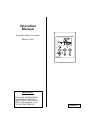
Operation
Manual
Simplifi ed Wired Controller
Model: CIS01

2
P5415477
1. Safety Summary
Signal Words
Indicates a hazardous situation that, if not avoided, could result in death or
serious injury.
Indicates a hazardous situation that, if not avoided, could result in minor or
moderate injury.
Indicates information considered important, but not hazard-related (for
example, messages relating to property damage).
General Precautions
To reduce the risk of serious injury or death, read these instructions
thoroughly and follow all warnings or cautions included in all manuals that
accompanied the product and are attached to the unit. Refer back to these
safety instructions as needed.
● This system, including this controller, should be installed by personnel certifi ed by Johnson
Controls, Inc. Personnel must be qualifi ed according to local, state and national building and safety
codes and regulations. Incorrect installation could cause leaks, electric shock, fi re or an explosion.
In areas where Seismic Performance requirements are specifi ed, the appropriate measures
should be taken during installation to guard against possible damage or injury that might occur in
an earthquake. If the unit is not installed appropriately correctly, injuries may occur because of a
falling unit
● Use appropriate Personal Protective Equipment (PPE), such as gloves, protective goggles and
electrical protection equipment and tools suited for electrical operation purposes.
● When transporting, be careful when picking up, moving and mounting these units. Although the
controller may be packed using plastic straps, do not use them for transporting from one location to
another. Do not stand on or put any material on the controller.
● When installing the controller cabling to the units, do not touch or adjust any safety devices inside
the indoor or outdoor units. All safety features, disengagement, and interlocks must be in place
and functioning correctly before the equipment is put into operation. If these devices are improperly
adjusted or tampered with in any way, a serious accident can occur. Never bypass, wire around, or
jump-out any safety device or switch.
● Use only Johnson Controls recommended, provided as standardized, or replacement parts.
● Johnson Controls will not assume any liability for injuries or damage caused by not following steps
outlined or described in this manual. Unauthorized modifi cations to Johnson Controls products are
prohibited as they…
◦ May create hazards which could result in death, serious injury or equipment damage;
◦ Will void product warranties;
◦ May invalidate product regulatory certifi cations;
◦ May violate OSHA standards;
Take the following precautions to reduce the risk of property damage.
● Do not touch the main circuit board or electronic components in the controller or remote devices.
Make sure that dust and/or steam does not accumulate on the circuit board.
● When installing the unit in a hospital or other facility where electromagnetic waves are generated
from nearby medical and/or electronic devices, be prepared for noise and electronic interference
Electromagnetic Interference (EMI). Do not install where the waves can directly radiate into
the electrical box, controller cable, or controller. Inverters, appliances, high-frequency medical
equipment, and radio communications equipment may cause the unit to malfunction.
The operation of the unit may also adversely affect these same devices. Install the unit at least 10
ft. (approximately 3m) away from such devices.
● Locate the controller at a distance of at least three feet (approximately 1m) between the indoor unit
and electric lighting. Otherwise, the receiver part of the unit may have diffi culty receiving operation
commands.

P5415477
3
● If the controller is installed in a location where electromagnetic radiation is generated, make sure that
the controller is shielded and cables are sleeved inside conduit tubing.
● If there is a source of electrical interference near the power source, install noise suppression equipment
(fi lter).
● During the run test, check the unit’s operation temperature. If the unit is used in an environment where
the temperature exceeds the operation boundary, it may cause severe damage. Check the operation
temperature boundary in the manual. If there is no specifi ed temperature, use the unit within the
operation temperature boundary of 35° to 104°F (0 to 40°C).
● Perform properly electrical wiring work. The details of the electrical wiring connection is described in the
“Electrical Wiring” of Installation and Maintenance Manual for CIS01.
Installation Precautions
Take the following precautions to reduce the risk of electric shock, fi re or
explosion resulting in serious injury or death:
● If the remote sensors are not used with this controller, then do not install this controller…
▫ In a room where there is no thermostat.
▫ Where the unit is exposed to direct sunshine or direct light.
▫ Where the unit is in close proximity to a heat source.
▫ Where hot/cold air from the outdoors, or a draft from elsewhere (such as air vents, diffusers or
grilles) can affect air circulation.
▫ In areas with poor air circulation and ventilation.
● Perform a run test using the controller to ensure normal operation. Safety guards, shields, barriers,
covers, and protective devices must be in place while the compressor/unit is operating. During the run
test, keep fi ngers and clothing away from any moving parts.
After installation work for the system has been completed, explain the “Safety Precautions,” use, and
maintenance of the unit to the customer according to the information in all manuals that accompanied the
system. All manuals and warranty information must be given to the user or left near the Indoor Unit.
Electrical Precautions
Take the following precautions to reduce the risk of electric shock, fi re or
explosion resulting in serious injury or death:
● Only use electrical protection equipment and tools suited for this installation.
● Insulate the controller against moisture and temperature extremes.
● Use specifi ed cables between units and the controller.
● Communication cabling shall be a minimum of 18-Gauge, 2-Conductor, Stranded, Shielded Copper.
Shielded cable must be used in all areas to reduce the potential for communication errors. When
shielded cabling is applied, proper bonding and termination of the cable shield is required as per
Johnson Controls guidelines. Plenum and riser ratings for communication cables must be considered
per application and local code requirements.
● The polarity of the input terminals is important, so be sure to match the polarity when using contacts that
have polarity.
● Highly dangerous electrical voltages may be used in this system. Carefully refer to the wiring diagram
and these instructions when wiring. Improper connections and inadequate grounding can cause serious
injury or death.
● Before installing the controller or remote devices, ensure that the indoor and outdoor unit operation has
been stopped. Further, be sure to wait at least fi ve minutes before turning off the main power switch to
the indoor or outdoor units. Otherwise, water leakage or electrical breakdown may result.
● Do not open the service cover or access panel to the indoor or outdoor units without turning OFF the
main power supply. Before connecting or servicing the controller or cables to indoor or outdoor units,
open and tag all disconnect switches. Never assume electrical power is disconnected. Check with a
meter and equipment.
● Use an exclusive power supply at the controller’s rated voltage.

4
P5415477
● Be sure to install circuit breakers (ground fault interrupter, isolating switch, molded case circuit breaker,
and so forth) with the specifi ed capacity. Ensure that the wiring terminals are tightened securely to
recommended torque specifi cations.
● Clamp electrical wires securely with a cord clamp after all wiring is connected to the terminal block. In
addition, run wires securely through the wiring access channel.
● When installing the power lines, do not apply tension to the cables. Secure the suspended cables at
regular intervals, but not too tightly.
● Make sure that the terminals do not come into contact with the surface of the electrical box. If the
terminals are too close to the surface, it may lead to failures at the terminal connection.
● Do not clean with, or pour water into, the controller as it could cause electric shock and/or damage the
unit. Do not use strong detergent such as a solvent. Clean with a soft cloth.
● Verify that the ground wire is securely connected. Do not connect ground wiring to gas piping, water
piping, lighting conductor, or telephone ground wiring.

P5415477
5
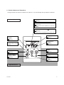
2. Switch Names and Functions
The fi gure below shows all the indications for reference. The actual display during operation is different.
Display Part
Swing Louver
Indicator
( Page 7)
Fan Speed Indicator
( Page 7)
Operation Mode
Selection Switch
( Page 6)
On/Off Switch
( Page 8)
Operation Mode
Indicator
( Page 6)
RUN LED (Green)
Indicates that the unit is
working.
Temperature Setting
Switch
( Page 7)
Operation Part
Fan Speed Selection
Switch
( Page 7)
Swing Louver Switch
( Page 7)
Alarm Code Indicator
(
Page 10)
Indicates when the air conditioner is in abnormal
condition.
Operation Lock Indicator
(
Page 8)
Indicates when the operation lock function is set.
Setting Temperature Indicator
( Page 7)

6
P5415477
<Function>
* Cooling Operation (COOL):
To decrease the room temperature.
* Heating Operation (HEAT):
To increase the room temperature.
* Dry Operation (DRY):
To decrease the room temperature and passively
reduce the humidity in the room.
* Cooling/Heating Automatic Operation (AUTO):
To set automatic mode changeover especially
for spring/summer or when temperature range
throughout a day is wide.
* Airfl ow Operation (FAN):
To circulate the air in the room.
<Before Operation>
Turn ON the power supply for the air conditioner.
To protect the compressor unit, the power
supply should be energized 12 hours before the
startup operation is begun. Do not turn OFF
the power supply during in-season heating or
cooling operation.
Make sure that the outdoor unit is always free
of ice and snow. If snow covered, remove it by
using hot water (cooler than 122
o
F (50
o
C)).
If the water temperature is higher than 122
o
F
(50
o
C), it will damage plastic parts.
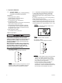
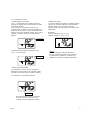
3. Operation Method
3.1 Operation Mode
(Cooling, Heating, Dry, Cooling/Heating
Automatic and Airfl ow Operation)
By pressing “Mode”,
the operation mode changes as follows.
NOTE:
Function selection setting is required for “AUTO”
operation mode. Refer to Installation Manual
and Service Manual for detailed information.
DRY
HEAT
COOL
FAN
(AUTO )
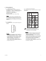
3.2 Automatic Cooling/Heating Operation
In case dual setpoint is selected in automatic
cooling/heating operation*, during auto mode
both cooling setpoint and heating setpoint can be
selected.
By default, temperature when the cooling/heating
mode changes are as follows.
Cooling mode changes to heating mode when the
indoor temperature is heating setpoint -2°F (-1°C).
Heating mode changes to cooling mode when the
indoor temperature is cooling setpoint +2°F (+1°C).
By pressing “Mode”,
the operation mode changes as follows.
NOTES:
• For Auto COOL/HEAT, though the temperature
indication on display changes by pressing
“Mode”, the actual operation mode remains
as “AUTO” and it does not change between
AUTO COOL and AUTO HEAT.
• Function selection setting is needed for
the use of automatic cooling/heating
operation and changing AUTO HEAT/COOL
temperature. Refer to Installation Manual and
Service Manual for detailed information.
DRY
HEAT
COOL
(AUTO )
(AUTO )
FAN
NOTE:
In case of AUTO COOL indication
* NOTE:
The function selection setting is required for
“Dual setpoint activation”.

P5415477
7
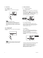
4.2 Fan Speed
By pressing “Fan”, the fan speed changes as
follows.
NOTES:
• During the dry operation, the fan speed is
automatically adjusted to “LOW ” and cannot
be changed to another fan speed. (“LOW ”
is NOT displayed on the LCD (liquid crystal
display) at this time. The present setting
condition is displayed on the LCD.)
• The fan speed settings “HIGH2” and (or)
“AUTO” might not be available depending on
the type of indoor unit.
LOW
MEDIUM
HIGH
HIGH2
AUTO
4. Setting Method
4.1 Temperature Setting
By pressing “Temp ˄ ”, the temperature is
increased by 1°F (0.5°C). (Max. 86°F (30°C))
By pressing “ ˅ Temp”, the temperature is
decreased by 1°F (0.5°C).
(Cooling, Dry, Airfl ow operation:
Min. 66°F (19°C))
(Heating operation: Min. 62°F (17°C))
NOTE:
Minimum and maximum temperature levels
can be adjusted by setting the lower limit (set
temperature for cooling) and the upper limit
(set temperature for heating) from the function
selection.
4.3 Swing Louver Direction
By pressing “Louver”, the louver direction changes
as follows.
NOTES:
• The airfl ow angle is different for each indoor
unit type. Check for detailed information in
“Swing Louver Direction” of each operation
manual for indoor unit.
• Louver action as depicted on the LCD display
might not mimic the actual movement of the
louver during the auto-swing operation.
To adjust louver position, fi rst set the angle
new angle on the LCD display.
• Louver action might not stop immediately after
the switch is pressed.
: The Auto-swing operation starts.
At this time, the louver graphic swings
repeatedly on the LCD display.
Recommended
Angle
Auto-Swing
Recommended
Angle
Angle
Range
Angle
Range
LCD Indication COOL, DRY HEAT, FAN

8
P5415477
6. Other Indicators
6.1 In Normal Conditions
6.1.2 Thermo-controller
The fan speed is changed to “LOW ” at the
thermo-controller switch. However, the graphic
indication remains unchanged. (Only in the
heating operation mode.)
6.1.3 Defrost
• Defrost Operation
The “ • ” is turned ON during the defrosting.
The indoor fan is stopped although the graphic
indication is unchanged.
The louver is fi xed at the horizontal position.
The graphic louver symbol on the LCD remains
animated.
•
Operation Stoppage during Defrosting Operation
The RUN LED (Green) goes out when the
operation is stopped during defrosting.
However, the operation continues with the “ • ”
displayed, and the unit stops after the
defrost operation is fi nished.
6.1.1 Central Control
When remote control operation is restricted (all
functions)
The central control “
” turns ON. If the remote
control restriction is set from the central controller,
the settings for “RUN”, “Operation Mode”,
“Temperature Setting”, “Fan Speed”, and “Louver”
are not accessible from the controller.
Turned ON
Turned ON
5. Operation
5.1 Operation Start
Press “On/Off”.
The run indicator turns ON and the operation
initiates.
NOTE:
Temperature/Airfl ow Setting
The setting condition is entered into memory
once the setting is confi rmed, therefore a
daily setting is not required. In cases where a
change of setting is required, refer to items 3.1
to 4.3.
NOTE:
After the heating operation is halted, the airfl ow
operation may be activated for approximately
two minutes.
5.2 Operation Stop
Press “On/Off” again.
The run indicator is turned OFF and the operation
is halted.

P5415477
9
6.1.4 Operation Control
• Supplying Electrical Power
The “ • ” is activated when electrical power is
supplied to outdoor unit for the fi rst time or after
long disconnection.
In this case, the compressor is now in the
preheat stage. Operation might be delayed by a
maximum of four hours. Do not cut power to the
outdoor unit during seasonal heating and cooling
operation. Refer to outdoor unit manuals for
details.
• During Hot Start (Heating Operation Only)
The “ • ” is turned ON.
• Different Operation Mode
The operation mode set by the controller is
different from the outdoor unit operation mode.
(Except for the heat recovery system models.)
The operation mode indicator fl ashes.
This indicator fl ashes when a command
to COOL has been set by way of the
controller during a HEATING operation.
Turned ON
Turned ON
Flashing
• Setback Operation
In case the setback operation is enabled and the
card key is removed, setpoint is compensated
and fan operate at “Low” speed. While in
setback mode, the boundary lines on the screen
disappears.
By default,
Cooling: Setpoint +4°F (+2.5°C)
Heating: Setpoint - 4°F (-2.5°C)
NOTE:
Function selection setting is needed for
the use of setback operation and changing
compensation for setback. Contact your
distributor or dealer for detailed information.

10
P5415477
6.2 In Alarm Conditions
6.2.1 Alarms
• The RUN LED (Red) is fl ashing.
• The indoor unit number, alarm code, model
code, and the connected number of indoor units
are displayed on LCD.
• In cases where a number of indoor units are
connected, the above items for each indoor unit
are displayed one by one.
6.2.2 Power Failure
• All indicators are DARK.
• Once a unit is shut down by a power failure for
longer than 2 seconds, it cannot be restarted
after the power recovers. Repeat starting
procedures again.
• In instances where the power failure and
recovery occur within 2 seconds, the unit
restarts automatically.
6.2.3 Electronic Interference
For instance, if a unit is in a shutdown state and
all indicators are OFF, this condition could have
been induced by the reaction of the unit’s micro-
computer fail-safe protections against electronic
interference (EMI). If this is the case, perform
restart procedures.

P5415477
11

LIT-12012042
Issued Oct, 2018
P5415477-rev.3
© 2018 Johnson Controls, Inc.
-
 1
1
-
 2
2
-
 3
3
-
 4
4
-
 5
5
-
 6
6
-
 7
7
-
 8
8
-
 9
9
-
 10
10
-
 11
11
-
 12
12


Johnson Controls CIS01 Operating instructions
- Category
- Split-system air conditioners
- Type
- Operating instructions
Ask a question and I''ll find the answer in the document
Finding information in a document is now easier with AI
Related papers
-
Johnson Controls HIFC012B21S User manual
-
Johnson Controls HIC2024B21S User manual
-
-
Johnson Controls VRF Wall Mount Indoor Unit User manual
-
York CIC4048B21S User manual
-
-
-
-
-
Other documents
-
York VRF 2 -Way Cassette Indoor Unit User manual
-
-
-
York VRF EconoFresh Kit Indoor Unit User manual
-
York VRF Ducted High Static Indoor Unit User manual
-
-
-
York VRF Ducted Slim Indoor Unit User manual
-
-