WIKA CPH6300-S1 Operating instructions
- Category
- Measuring & layout tools
- Type
- Operating instructions
This manual is also suitable for

Operating instructions
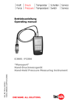
Betriebsanleitung
EN
DE
Hand-held pressure indicator, model CPH6300
Hand-Held Druckmessgerät, Typ CPH6300
Hand-held pressure indicator, model CPH6300

2
14043054.02 08/2017 EN/DE
WIKA operating instructions, model CPH6300
EN
DE
Operating instructions model CPH6300 Page 3 - 46
Betriebsanleitung Typ CPH6300 Seite 47 - 91
Further languages can be found at www.wika.com.
© 08/2017 WIKA Alexander Wiegand SE & Co. KG
All rights reserved. / Alle Rechte vorbehalten.
WIKA
®
is a registered trademark in various countries.
WIKA
®
ist eine geschützte Marke in verschiedenen Ländern.
Prior to starting any work, read the operating instructions!
Keep for later use!
Vor Beginn aller Arbeiten Betriebsanleitung lesen!
Zum späteren Gebrauch aufbewahren!

3WIKA operating instructions, model CPH6300
EN
14043054.02 08/2017 EN/DE
Contents
Contents
1. General information 5
2. Short overview 6
2.1 Overview . . . . . . . . . . . . . . . . . . . . . . . . 6
2.2 Description . . . . . . . . . . . . . . . . . . . . . . . 6
2.3 Scope of delivery . . . . . . . . . . . . . . . . . . . . . 7
3. Safety 7
3.1 Explanation of symbols . . . . . . . . . . . . . . . . . . . 7
3.2 Intended use. . . . . . . . . . . . . . . . . . . . . . . 7
3.3 Improper use . . . . . . . . . . . . . . . . . . . . . . 8
3.4 Personnel qualification . . . . . . . . . . . . . . . . . . . 8
3.5 Labelling, safety marks . . . . . . . . . . . . . . . . . . . 9
4. Transport, packaging and storage 10
4.1 Transport . . . . . . . . . . . . . . . . . . . . . . . .10
4.2 Packaging and storage . . . . . . . . . . . . . . . . . . . 10
5. Commissioning, operation 11
5.1 Operation . . . . . . . . . . . . . . . . . . . . . . . . 11
5.1.1 Display. . . . . . . . . . . . . . . . . . . . . . . . . . . . . . . . . . . . . .11
5.1.2 Controls . . . . . . . . . . . . . . . . . . . . . . . . . . . . . . . . . . . . .12
5.2 Commissioning . . . . . . . . . . . . . . . . . . . . . .13
5.3 Configuration of the instrument . . . . . . . . . . . . . . . . 13
5.4 Special functions . . . . . . . . . . . . . . . . . . . . . 20
5.4.1 Different pressure units. . . . . . . . . . . . . . . . . . . . . . . . . . . . .20
5.4.2 Different measuring modes . . . . . . . . . . . . . . . . . . . . . . . . . .20
5.4.3 Sea level correction for absolute pressure sensors . . . . . . . . . . . . .21
5.4.4 Averaging . . . . . . . . . . . . . . . . . . . . . . . . . . . . . . . . . . . .21
5.4.5 Rate of change of pressure (only for sensor connection 1) . . . . . . . . .22
5.5 Data logger . . . . . . . . . . . . . . . . . . . . . . . 23
5.5.1 Manual records . . . . . . . . . . . . . . . . . . . . . . . . . . . . . . . . .24
5.5.2 Automatic recording with adjustable cycle . . . . . . . . . . . . . . . . . .26
5.6 Universal output . . . . . . . . . . . . . . . . . . . . . 29
5.6.1 USB interface . . . . . . . . . . . . . . . . . . . . . . . . . . . . . . . . . .29
5.6.2 Analogue output . . . . . . . . . . . . . . . . . . . . . . . . . . . . . . . .29
5.7 Adjustment of the instrument . . . . . . . . . . . . . . . . . 30
5.8 Pressure connection at the pressure sensors. . . . . . . . . . . . 30
5.9 Real-time clock . . . . . . . . . . . . . . . . . . . . . .30
5.10 Alarm. . . . . . . . . . . . . . . . . . . . . . . . . 31

4 WIKA operating instructions, model CPH6300
EN
14043054.02 08/2017 EN/DE
6. Faults 31
7. Maintenance, cleaning and recalibration 33
7.1 Maintenance. . . . . . . . . . . . . . . . . . . . . . . 33
7.2 Cleaning . . . . . . . . . . . . . . . . . . . . . . . . 35
7.3 Recalibration. . . . . . . . . . . . . . . . . . . . . . . 35
8. Dismounting, return and disposal 36
8.1 Dismounting . . . . . . . . . . . . . . . . . . . . . . .36
8.2 Return . . . . . . . . . . . . . . . . . . . . . . . . .37
8.3 Disposal . . . . . . . . . . . . . . . . . . . . . . . . 37
9. Specifications 38
10. Accessories 45
Declarations of conformity can be found online at www.wika.com.
Contents

5WIKA operating instructions, model CPH6300
EN
14043054.02 08/2017 EN/DE
1. General information
■
The model CPH6300 hand-held pressure indicator described in the operating
instructions has been designed and manufactured using state-of-the-art technology.
All components are subject to stringent quality and environmental criteria during
production. Our management systems are certified to ISO 9001 and ISO 14001.
■
These operating instructions contain important information on handling the instrument.
Working safely requires that all safety instructions and work instructions are observed.
■
Observe the relevant local accident prevention regulations and general safety
regulations for the instrument's range of use.
■
The operating instructions are part of the product and must be kept in the immediate
vicinity of the instrument and readily accessible to skilled personnel at any time. Pass
the operating instructions on to the next operator or owner of the instrument.
■
Skilled personnel must have carefully read and understood the operating instructions
prior to beginning any work.
■
The general terms and conditions contained in the sales documentation shall apply.
■
Subject to technical modifications.
■
Factory calibrations / DKD/DAkkS calibrations are carried out in accordance with
international standards.
■
Further information:
- Internet address: www.wika.de / www.wika.com
- Relevant data sheet: CT 12.01
- Application consultant:
Tel.: +49 9372 132-9986
Fax: +49 9372 132-8767
Abbreviations, definitions
“XXX” Menu XXX will be selected
[XXX] Press XXX button
1. General information

6 WIKA operating instructions, model CPH6300
EN
14043054.02 08/2017 EN/DE
2. Short overview
2. Short overview
2.1 Overview
1
Sensor connection cable
2
Pressure connection channel 1
3
Pressure connection channel 2
4
Interface connector
5
Display
6
Controls
7
Reference pressure sensor model CPT6200
2.2 Description
The model CPH6300 hand-held pressure indicator is very-well suited for operation under
the most-adverse conditions due to its robust and waterproof design. Due to the high
accuracy of the sensor technology, the CPH6300 can be used for accurate pressure
measurement and also for calibration.
7
5
6
4
3
2
1

7WIKA operating instructions, model CPH6300
EN
14043054.02 08/2017 EN/DE
3. Safety
3.1 Explanation of symbols
WARNING!
... indicates a potentially dangerous situation that can result in serious injury
or death, if not avoided.
CAUTION!
... indicates a potentially dangerous situation that can result in light injuries
or damage to property or the environment, if not avoided.
Information
... points out useful tips, recommendations and information for efficient and
trouble-free operation.
3.2 Intended use
This CPH6300 hand-held pressure indicator can be used as a calibration instrument and
also for any application which requires high-accuracy pressure measurement.
This instrument is not permitted to be used in hazardous areas!
The instrument has been designed and built solely for the intended use described here,
and may only be used accordingly.
The technical specifications contained in these operating instructions must be observed.
Improper handling or operation of the instrument outside of its technical specifications
requires the instrument to be taken out of service immediately and inspected by an
authorised WIKA service engineer.
2. Short overview / 3. Safety
2.3 Scope of delivery
■
Hand-held pressure indicator model CPH6300 incl. 2 AAA batteries
■
One sensor connection cable per channel
■
3.1 calibration certificate in accordance with DIN EN 10204 for sensors
■
Choice of sensors
Cross-check scope of delivery with delivery note.

8 WIKA operating instructions, model CPH6300
EN
14043054.02 08/2017 EN/DE
Handle electronic precision measuring instruments with the required care (protect from
humidity, impacts, strong magnetic fields, static electricity and extreme temperatures,
do not insert any objects into the instrument or its openings). Plugs and sockets must be
protected from contamination.
The manufacturer shall not be liable for claims of any type based on operation contrary to
the intended use.
3.3 Improper use
WARNING!
Injuries through improper use
Improper use of the instrument can lead to hazardous situations and injuries.
▶
Refrain from unauthorised modifications to the instrument.
▶
Do not use the instrument within hazardous areas.
▶
Do not use the instrument with abrasive or viscous media.
▶
Observe the working conditions in accordance with chapter
9 “Specifications”.
▶
Always operate the instrument within its overload limits.
Any use beyond or different to the intended use is considered as improper use.
3.4 Personnel qualification
WARNING!
Risk of injury should qualification be insufficient
Improper handling can result in considerable injury and damage to
equipment.
▶
The activities described in these operating instructions may only be
carried out by skilled personnel who have the qualifications described
below.
Skilled personnel
Skilled personnel, authorised by the operator, are understood to be personnel who,
based on their technical training, knowledge of measurement and control technology and
on their experience and knowledge of country-specific regulations, current standards and
directives, are capable of carrying out the work described and independently recognising
potential hazards.
3. Safety

9WIKA operating instructions, model CPH6300
EN
14043054.02 08/2017 EN/DE
Special operating conditions require further appropriate knowledge, e.g. of aggressive
media.
3.5 Labelling, safety marks
Product label for model CPH6300-S1 or CPH6300-S2 (examble)
Product label for model CPT6200 (examble)
1
Product name
2
Date of manufacture (month-year)
3
Serial number and article number
4
Pressure measuring range and accuracy
Symbols
Before mounting and commissioning the instrument, ensure you read
the operating instructions!
2
1
3
04/2016
Transmitter CPT6200 for Hand-Held Instrument
3
4
2
1
3. Safety

10 WIKA operating instructions, model CPH6300
EN
14043054.02 08/2017 EN/DE
3. Safety / 4. Transport, packaging and storage
4. Transport, packaging and storage
4.1 Transport
Check the model CPH6300 hand-held pressure indicator and the model CPT6200
reference pressure sensor for any damage that may have been caused by transport.
Obvious damage must be reported immediately.
CAUTION!
Damage through improper transport
With improper transport, a high level of damage to property can occur.
▶
When unloading packed goods upon delivery as well as during internal
transport, proceed carefully and observe the symbols on the packaging.
▶
With internal transport, observe the instructions in chapter 4.2 “Packaging
and storage”.
If the instrument is transported from a cold into a warm environment, the formation of
condensation may result in instrument malfunction. Before putting it back into operation,
wait for the instrument temperature and the room temperature to equalise.
4.2 Packaging and storage
Do not remove packaging until just before mounting.
Keep the packaging as it will provide optimum protection during transport (e.g. change in
installation site, sending for repair).
Permissible conditions at the place of storage:
■
Storage temperature: -25 ... +70 °C (-13 ... +158 °F)
■
Humidity: 0 ... 95 % relative humidity (non-condensing)
Avoid exposure to the following factors:
■
Direct sunlight or proximity to hot objects
■
Mechanical vibration, mechanical shock (putting it down hard)
■
Soot, vapour, dust and corrosive gases
■
Hazardous environments, flammable atmospheres
This marking on the instruments indicates that they must not be disposed of
in domestic waste. The disposal is carried out by return to the manufacturer
or by the corresponding municipal authorities.

11WIKA operating instructions, model CPH6300
EN
14043054.02 08/2017 EN/DE
Store the instrument in its original packaging in a location that fulfils the conditions
listed above. If the original packaging is not available, pack and store the instrument as
described below:
1. Wrap the instrument in an antistatic plastic film.
2. Place the instrument, along with the shock-absorbent material, in the packaging.
3. If stored for a prolonged period of time (more than 30 days), place a bag containing a
desiccant inside the packaging.
4. Transport, packaging ... / 5. Commissioning, operation
5. Commissioning, operation
Personnel: Skilled personnel
Only use original parts (see chapter 10 “Accessories”).
5.1 Operation
5.1.1 Display
1
Main display: Current measured
value for sensor 1
2
Secondary display: Current
measured value for sensor 2 or
differential value between sensor 1
and sensor 2
3
logg arrow: Logger is ready
Arrow blinking: Automatic recording
(Logg CYCL) active
4
corr arrow: Zero point or slope
correction has been made
5
user arrow: Measured value is
specified in the freely configurable
user unit
6
Display arrows for measured value
units
7
Display elements for the display of the
Min/Max values, as well as the Tare
function and sea level correction
8
Battery status display
6
6
8
7
1
2
45 3

12 WIKA operating instructions, model CPH6300
EN
14043054.02 08/2017 EN/DE
5. Commissioning, operation
5.1.2 Controls
Instrument
on
Illumination
on
2 sec.
Instrument
off
MAX function
on/off
2 sec.
Delete MAX
value
TARE function
on
2 sec.
TARE function
off
5 sec.
Zero point
adjustment on
10 sec.
Zero point
adjustment off
MIN function
on/off
2 sec.
Delete MIN value
Change the
secondary
display
CH1 <-> CH2
<-> DIF
(only for 2-channel)
2 sec.
Main menu
Enter
configuration
if:
Hold function
on/off
A
Store measured
value
B
2 sec.
Clear memory?
2 sec.
Store cyclically
C
2 sec.
Stop storage?
2 sec.
Clear memory?
A = Logger functions deactivated
B = Logger function “Store measured value” activated via menu
C = Logger function “Store cyclically” activated via menu
= Press button
2 sec. = Press button for 2 seconds
For more information: see operating instructions

13WIKA operating instructions, model CPH6300
EN
14043054.02 08/2017 EN/DE
5. Commissioning, operation
5.2 Commissioning
1. Connect sensor and switch the instrument on with the [ON/OFF] button.
⇒
Following the segment test, the display displays short information about its
configuration:
rate sLo
Standard measurement is set.
rate FASt
Fast measurement is set.
rate P.det
Peak value detection is set.
The instrument is then ready for measurement.
5.3 Configuration of the instrument
The availability of some of the menu items is dependant on the current
instrument settings (e.g. a few menu items will be locked, if the logger
contains data).
1. To configure, press the [SET/MENU] button for 2 seconds.
⇒
The menu (main display SEt) is called up.
2. With the [SET/MENU] button, select the required menu branch.
3. Select the parameter with the [▶] button.
4. Change the parameter with the [▲] or [▼] buttons.
5. Step the parameter forward using the [▶] button.
6. Press the [SET/MENU] button.
⇒
Changes back to the main menu and saves the settings.
7. With [STORE/QUIT], the configuration is concluded.
If the [SET/MENU] and [STORE/QUIT] buttons are pressed, together for
longer than 2 seconds, the factory settings will be restored.
Data in the individual value logger (logger: Fvnc Stor) is displayed as
the initial menu
read Lo66: also see chapter 5.5 “Data logger”.
If no button is pressed within 2 minutes, the configuration of the instrument
will be interrupted. Changes made up until that point will not be saved!

14 WIKA operating instructions, model CPH6300
EN
14043054.02 08/2017 EN/DE
Menu Parameters
Values
Meaning
“MENU” ▶ ▲ or ▼
SEt
ConF
Set configuration: Generic settings
Unit: Selection of the measuring unit
1) 2)
UNiT
Cursor at bar,
mbar, ...
Measured values are denoted in the
corresponding unit; the units selectable are
dependent on the sensors.
Cursor at “user” The measured value is specified in the freely
configurable user unit: Linear calculation
base
bar, mbar Unit “user”: Base unit
dP
0000, 000.0 …
.0000
Unit “user”: Decimal point of the multiplication
factor
FaCT
-19999 ...
19999
Unit “user”: Multiplication factor
Sea level: Correction of the sea level
1) 2)
SL
oFF Sea level correction off
on Sea level correction on
(see chapter 5.4.3 “Sea level correction for
absolute pressure sensors”).
ALT
-2000 ... 9999 Sea level correction in [m] (only when sensor
1 SL = on)
rate
Rate: Measuring rate
1)
Slo Slow: Slow measuring rate (4 Hz filtered, low
power consumption)
FASt Fast: Fast measuring rate, filtered (> 1,000 Hz)
P.dEt Peak detection: Fast measuring rate, unfiltered
(1,000 Hz)
t.AU6
Averaging
1)
1 ... 120 Averaging interval in seconds, used by the
averaging function off.
oFF Averaging deactivated
1) Menu cannot be selected if there is data in the logger memory. If this is to be changed, the data must first be deleted (see chapter
5.5 “Data logger”).
2) This menu can only be selected if an appropriate sensor is connected to connection 1. When using a second corresponding
sensor on connection 2 then the settings are adopted.
3) Only for 2-channel version
5. Commissioning, operation

15WIKA operating instructions, model CPH6300
EN
14043054.02 08/2017 EN/DE
Menu Parameters
Values
Meaning
“MENU” ▶ ▲ or ▼
P.oFF
Auto power-off: Automatic switching off of the instrument
1 ... 120 Auto power-off delay in minutes. If no button is
pressed and there is no data transfer via the
serial interface, the instrument will switch itself off
after this interval.
oFF Auto power-off function inactive (continuous
operation)
Lite
Backlighting (factory setting: 5 s)
oFF No illumination
5 ... 120 Illumination automatically switches off after
5 ... 120 s.
on Illumination does not switch off
SEt
CALC
Set calculation: Calculated displays (derived from sensor 1)
1)
CALC
Selection of the calculation function
oFF No calculated display
dP:dt Rate of change of pressure
SPEd Airspeed through the orifice plate/pitot tube
FLo Flow / Air flow
“dP:dt”: Settings
base
Time unit for the rate of change of the pressure
PEr.S Change in pressure per second, e.g. mbar/s
PEr.n Change in pressure per minute, e.g. mbar/min
PEr.h Change in pressure per hour, e.g. mbar/h
t.int
Test duration, for which the pressure change display is
calculated
00:01 ... 1:00 Duration in [Minutes:Seconds], Factory setting:
0:01 = 1 s
1) Menu cannot be selected if there is data in the logger memory. If this is to be changed, the data must first be deleted (see chapter
5.5 “Data logger”).
2) This menu can only be selected if an appropriate sensor is connected to connection 1. When using a second corresponding
sensor on connection 2 then the settings are adopted.
3) Only for 2-channel version
5. Commissioning, operation

16 WIKA operating instructions, model CPH6300
EN
14043054.02 08/2017 EN/DE
Menu Parameters
Values
Meaning
“MENU” ▶ ▲ or ▼
“SPEd” or “FLo”: Settings
UNiT
SPEd: Airspeed unit
n:S Metres per second, m/s
kn:h Kilometres per hour, km/h
nPh Miles per hour, mph
knot knots
FLo: Volume flow or flow unit
n3:s Cubic metres per second, m³/s
n3:n Cubic metres per minute, m³/min
n3:h Cubic metres per hour, m³/s
L:S Litres per second, l/s
L:n Litres per minute, l/min
A
FLo: Flow /Volume flow - display - cross-section
10.0 … 1999.9,
2000 … 14000
Effective area of the channel in cm²
t
-100.0 ...
1000.0 °C
Air flow temperature
P.abs
100.0 ...
1999.9 mbar
Ambient pressure
dp
0000, 000.0,
00.00
Decimal point setting
strt
oFF, 1 … 1000 Minimum display, below which display 0 is forced.
SET
Out
Set output: Settings for universal output
Out
oFF Interface and analogue output deactivated
SEr Serial interface activated
dAC Analogue output activated
adr.
01.11 ... 91 Base address of the instrument for serial
communication (only with Out = SEr).
DAC
CH 1, CH 2 or
DIF CH
Measuring input which should be used for the
analogue output (if Out = DAC).
3)
1) Menu cannot be selected if there is data in the logger memory. If this is to be changed, the data must first be deleted (see chapter
5.5 “Data logger”).
2) This menu can only be selected if an appropriate sensor is connected to connection 1. When using a second corresponding
sensor on connection 2 then the settings are adopted.
3) Only for 2-channel version
5. Commissioning, operation

17WIKA operating instructions, model CPH6300
EN
14043054.02 08/2017 EN/DE
Menu Parameters
Values
Meaning
“MENU” ▶ ▲ or ▼
daC.0
sensor
dependent
e.g. -5.00 ...
5.00 mbar
Zero point setting for Out = DAC: Input of the
measured value with which the analogue output
should output 0 V.
daC.I
sensor
dependent
e.g. -5.00 ...
5.00 mbar
Slope setting for Out = DAC: Input of the
measured value with which the analogue output
should output 1 V.
SET
Corr
Set Corr: Adjustment of the measurement (1-channel version)
1)
Offs
Zero point adjustment/offset of the sensor
oFF No zero point adjustment for the sensor.
sensor
dependent
e.g. -5.00 ...
5.00 mbar
The zero point of sensor 1 will be displaced by
this value to compensate for deviations in the
probe or in the measuring instrument.
sCAL
Slope correction for the sensor
oFF No slope correction for the sensor
-2,000 ... 2,000 The measuring scale will be changed by this
factor [%] to compensate deviations of probe /
measuring instrument.
SET
Corr
Set Corr: Adjustment of the measurement (2-channel version)
1) 3)
OFS.I
Zero point adjustment/offset of sensor 1
oFF No zero point adjustment for the sensor 1.
sensor
dependent
e.g. -5.00 ...
5.00 mbar
The zero point of sensor 1 will be displaced by
this value to compensate for deviations in the
probe / measuring instrument.
SCL.I
Slope correction for sensor 1
oFF No slope correction for sensor 1
-2,000 ... 2,000 The measuring scale will be changed by this
factor [%] to compensate deviations of probe /
measuring instrument.
1) Menu cannot be selected if there is data in the logger memory. If this is to be changed, the data must first be deleted (see chapter
5.5 “Data logger”).
2) This menu can only be selected if an appropriate sensor is connected to connection 1. When using a second corresponding
sensor on connection 2 then the settings are adopted.
3) Only for 2-channel version
5. Commissioning, operation

18 WIKA operating instructions, model CPH6300
EN
14043054.02 08/2017 EN/DE
Menu Parameters
Values
Meaning
“MENU” ▶ ▲ or ▼
OFS.2
Zero point adjustment/offset of sensor 2
oFF No zero point adjustment for sensor 2.
sensor
dependent
e.g. -5.00 ...
5.00 mbar
The zero point of sensor 2 will be displaced by
this value to compensate for deviations in the
probe or in the measuring instrument.
SCL.2
Slope correction for sensor 2
oFF No slope correction for sensor 2
-2,000 …
2,000
The measuring scale will be changed by this
factor [%] to compensate deviations of probe and
measuring instrument.
SET
AL.
Set Alarm: Alarm function configuration
On/No.So Alarm sensor 1 on, with buzzer/without buzzer
OFF No alarm function for sensor 1
AL.Lo/1
Sensor1-Min
... AL.1-Hi
Min alarm limit sensor 1 (not if AL.1 = oFF)
Sensor1-Min is the lower scale range limit of
sensor 1.
AL.Hi/1
AL.1-Lo ...
Sensor1-Max
Max alarm limit sensor 1 (not if AL.1 = oFF)
Sensor1-Max is the upper scale range limit of
sensor 1.
AL. 2
On/No.So Alarm sensor 2 on, with buzzer/without buzzer
OFF No alarm function for sensor 2
AL.Lo/2
Sensor2-Min
... AL.2-Hi
Min alarm limit sensor 2 (not if AL.2 = oFF)
Sensor1-Min is the lower scale range limit of
sensor 2.
AL.Hi/2
AL.2-Lo ...
Sensor2-Max
Max alarm limit sensor 2 (not if AL.2 = oFF)
Sensor1-Max is the upper scale range limit of
sensor 2.
AL.
DIF
On/No.So Alarm on, with/without buzzer (1-channel version)
or alarm sensor difference on, with/without
buzzer (2-channel version).
OFF no alarm function (1-channel version) or no
alarm function for sensor difference (2-channel
version.)
1) Menu cannot be selected if there is data in the logger memory. If this is to be changed, the data must first be deleted (see chapter
5.5 “Data logger”).
2) This menu can only be selected if an appropriate sensor is connected to connection 1. When using a second corresponding
sensor on connection 2 then the settings are adopted.
3) Only for 2-channel version
5. Commissioning, operation

19WIKA operating instructions, model CPH6300
EN
14043054.02 08/2017 EN/DE
Menu Parameters
Values
Meaning
“MENU” ▶ ▲ or ▼
AL.Lo
DIF
-19999…
AL.DIF-Hi
Min alarm limit difference (not if AL.diff = oFF)
3)
Sensor-Min ...
AL.Hi
Min alarm limit sensor (not if AL. = oFF) Sensor-
Min is the lower scale range limit of the sensor.
AL.Hi
DIF
AL.DIF-Lo…
19999
Max alarm limit difference (not if AL.diff = oFF)
3)
AL.Lo ...
Sensor-Max
Max alarm limit sensor (not if AL. = oFF) Sensor-
Max is
SET
Lo66
Set Logger: Logger function configuration
1)
Selection of the logger function
1)
Fvnc
CYCL Cyclic: Logger function “cyclic logger”
Stor Store: Logger function “individual value logger”
oFF No logger function
CYCL
00:01 ... 60:00 Cycle time for cyclic logger [minutes:seconds]
1)
Lo.Po
on/oFF Low-power logger with very low power supply
(only if cyclic logger with slow measuring rate)
1)
SET
CLOC
Set Clock: Setting of the real-time clock
CLOC
HH:MM Clock: Set time hours:minutes
YEAr
YYYY Year: Set year
date
TT.MM Date: Set time day.month
read
Lo66
rEAd Logg: Reading the individual logger data
See chapter 5.5.1 “Manual records”
1) Menu cannot be selected if there is data in the logger memory. If this is to be changed, the data must first be deleted (see chapter
5.5 “Data logger”).
2) This menu can only be selected if an appropriate sensor is connected to connection 1. When using a second corresponding
sensor on connection 2 then the settings are adopted.
3) Only for 2-channel version
5. Commissioning, operation

20 WIKA operating instructions, model CPH6300
EN
14043054.02 08/2017 EN/DE
5.4 Special functions
5.4.1 Different pressure units
Depending on the connected sensor, in “MENU (Unit)” different units can be selected.
Depending on the measuring range, the selection may be limited!
User unit
For units which are not covered by the units imprinted on the display, a manual setting
can be made via the user unit.
Example:
So that the unit kg/cm² can be displayed with a CPT6200 reference pressure sensor, this
must be set:
kg/cm² Torr atm at
bASE user
bar mbar bar bar
DP user
.0000 .0000 .0000 .0000
FACt user
1.0197 .7433 .9869 1.0197
5.4.2 Different measuring modes
The instrument supports 3 different measuring modes for various purposes. Two
of these,
P.dEt and FASt, operate with an increased measuring frequency of
> 1,000 measurements/s.
5.4.2.1 Standard measurement (slow)
rate sLo
Measuring rate 4 Hz, averaging and filter functions are active.
Application range:
Measurement of slow pressure changes and static pressures, e.g. leak
testing, atmospheric pressure measurements, etc.
Highest measuring accuracy, insensitive to disturbances, low current
consumption.
5.4.2.2 Peak value detection (Peak detection)
rate P.det
Measuring rate > 1,000 Hz; the value is displayed unfiltered.
Field of application in combination with logger function:
Measurement of pressure spikes or fluctuating pressures with a
resolution of < 1 ms. The cyclic logger function records the arithmetic
mean value, the highest and the lowest peak during the chosen time
interval.
5. Commissioning, operation
Page is loading ...
Page is loading ...
Page is loading ...
Page is loading ...
Page is loading ...
Page is loading ...
Page is loading ...
Page is loading ...
Page is loading ...
Page is loading ...
Page is loading ...
Page is loading ...
Page is loading ...
Page is loading ...
Page is loading ...
Page is loading ...
Page is loading ...
Page is loading ...
Page is loading ...
Page is loading ...
Page is loading ...
Page is loading ...
Page is loading ...
Page is loading ...
Page is loading ...
Page is loading ...
Page is loading ...
Page is loading ...
Page is loading ...
Page is loading ...
Page is loading ...
Page is loading ...
Page is loading ...
Page is loading ...
Page is loading ...
Page is loading ...
Page is loading ...
Page is loading ...
Page is loading ...
Page is loading ...
Page is loading ...
Page is loading ...
Page is loading ...
Page is loading ...
Page is loading ...
Page is loading ...
Page is loading ...
Page is loading ...
Page is loading ...
Page is loading ...
Page is loading ...
Page is loading ...
Page is loading ...
Page is loading ...
Page is loading ...
Page is loading ...
Page is loading ...
Page is loading ...
Page is loading ...
Page is loading ...
Page is loading ...
Page is loading ...
Page is loading ...
Page is loading ...
Page is loading ...
Page is loading ...
Page is loading ...
Page is loading ...
Page is loading ...
Page is loading ...
Page is loading ...
Page is loading ...
-
 1
1
-
 2
2
-
 3
3
-
 4
4
-
 5
5
-
 6
6
-
 7
7
-
 8
8
-
 9
9
-
 10
10
-
 11
11
-
 12
12
-
 13
13
-
 14
14
-
 15
15
-
 16
16
-
 17
17
-
 18
18
-
 19
19
-
 20
20
-
 21
21
-
 22
22
-
 23
23
-
 24
24
-
 25
25
-
 26
26
-
 27
27
-
 28
28
-
 29
29
-
 30
30
-
 31
31
-
 32
32
-
 33
33
-
 34
34
-
 35
35
-
 36
36
-
 37
37
-
 38
38
-
 39
39
-
 40
40
-
 41
41
-
 42
42
-
 43
43
-
 44
44
-
 45
45
-
 46
46
-
 47
47
-
 48
48
-
 49
49
-
 50
50
-
 51
51
-
 52
52
-
 53
53
-
 54
54
-
 55
55
-
 56
56
-
 57
57
-
 58
58
-
 59
59
-
 60
60
-
 61
61
-
 62
62
-
 63
63
-
 64
64
-
 65
65
-
 66
66
-
 67
67
-
 68
68
-
 69
69
-
 70
70
-
 71
71
-
 72
72
-
 73
73
-
 74
74
-
 75
75
-
 76
76
-
 77
77
-
 78
78
-
 79
79
-
 80
80
-
 81
81
-
 82
82
-
 83
83
-
 84
84
-
 85
85
-
 86
86
-
 87
87
-
 88
88
-
 89
89
-
 90
90
-
 91
91
-
 92
92


WIKA CPH6300-S1 Operating instructions
- Category
- Measuring & layout tools
- Type
- Operating instructions
- This manual is also suitable for
Ask a question and I''ll find the answer in the document
Finding information in a document is now easier with AI
in other languages
- Deutsch: WIKA CPH6300-S1 Bedienungsanleitung
Related papers
-
WIKA CPH6K3-V1 Owner's manual
-
-
-
-
-
-
-
-
-
Other documents
-
 Tecsis Manoport E3905 Operating instructions
-
Omega GMH3750 Owner's manual
-
PeakTech 8005 Operating instructions
-
Dostmann LOG40 User manual
-
VOLTCRAFT DL-111K Owner's manual
-
Laserliner SoundTest-Master Owner's manual
-
VOLTCRAFT DL-151AN Anometer Operating Instructions Manual
-
-
-
