Page is loading ...

HSLink System
User’s Guide


© Copyright 2000 ADLINK TECHNOLOGY INC.
All Rights Reserved.
Manual Rev. 1.00: Oct. 23, 2000
The information in this document is subject to change without prior notice in
order to improve reliability, design and function and does not represent a
commitment on the part of the manufacturer.
In no event will the manufacturer be liable for direct, indirect, special,
incidental, or consequential damages arising out of the use or inability to
use the product or documentation, even if advised of the possibility of such
damages.
This document contains proprietary information protected by copyright. All
rights are reserved. No part of this manual may be reproduced by any
mechanical, electronic, or other means in any form without prior written
permission of the manufacturer.
Trademarks
NuDAQ
, NuIPC
, NuDAM
, NuPRO
, HSLink
are registered trademarks
of ADLINK TECHNOLOGY INC. Other product names mentioned herein are
used for identification purposes only and may be trademarks and/or
registered trademarks of their respective companies.


Contents • i
Contents
Chapter 1 HSLink Introduction....................................................1
1.1 What Is HSLink System..............................................................................1
1.1.1 Product Overview............................................................................1
1.1.2 Features of HSLink System..........................................................2
1.1.3 Application of HSLink .....................................................................3
1.2 Specifications of HSLink System.............................................................7
1.3 HSLink Series Products.............................................................................8
1.4 HSLink Technical Information...................................................................9
1.4.1 HSLink Technology Brief...............................................................9
1.4.2 Terminology of HSLink.................................................................12
1.4.3 System configurations.................................................................12
1.4.4 Wiring...............................................................................................14
1.4.5 Networking Topology....................................................................16
1.4.6 I/O refreshing rate of HSLink system.......................................16
1.4.7 Communication error handling..................................................17
1.5 Software Supporting.................................................................................18
1.6 How to Install a HSLink System..............................................................18
Chapter 2 HSLink-Master...........................................................20
2.1 Board Overview..........................................................................................20
2.2 Specifications.............................................................................................21
2.3 Configuration...............................................................................................22
2.4 PIN Assignment..........................................................................................22
2.5 Function Description.................................................................................23
Chapter 3 NT DLL Programming...............................................24
3.1 Installation of HSLink DLL Driver............................................................24
3.2 ADLINK HSLink Master Utility..................................................................26
3.3 How to Program with DLL........................................................................29
Chapter 4
ISaGRAF Programming
.....................................................46
4.1 Installation of ISaGRAF Driver.................................................................46
4.2 Restore I/O Board and I/O Equipment....................................................48
4.3 Restore Sample Programs......................................................................50
4.4 Configuration of HSLink−R8DI16 module.............................................51
4.5 Configuration of HSLink−DI16DO16 module .......................................53

ii • Contents
4.6 Configuration of HSLink−DI32 module..................................................55
4.7 Configuration of HSLink−DO32 module................................................57
Product Warranty/Service ..........................................................59

How to use This Manual
This manual is written to help you to use the HSLink series products. It
describes the versatile functions and the operation theorem of the HSLink.
This manual is divided into 4 chapters:
Chapter 1 “HSLink Introduction” gives an overview of the HSLink system
regarding system features, applications, and specifications.
Chapter 2 “HSLink-Master” describes detail information of HSLink
master.
Chapter 3 “NT DLL Programming” describes installation procedures of
DLL driver and functions supported.
Chapter 4 “ISaGRAF Programming” describes the detail installation
procedures of drivers, I/O boards…etc, and explains how to
program by ISaGRAF.


HSLink Introduction • 1
1
HSLink Introduction
1.1 What Is HSLink System
HSLink is an innovative distributed I/O technology which allows thousands
of I/O points to be scanned in mini-second-level real time by using 1 to N
mater-slave architecture. The HSLink master is a PCI-bus card plugged into
CPU Unit of PCC, and by using commercial Ethernet cable with RJ45
connector user may easily settle the HSLink slaves as close as possible to
sensor devices. Thus the wiring effort is dramatically reduced.
This product series is to satisfy those who want:
l Remote control based on PC architecture
l Simple wiring solution for remote I/O
l A vast, up to hundreds or more, number of I/O.
l Real-time sensitive I/O
l High speed data acquisition
1.1.1 Product Overview
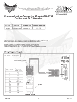
The following drawing shows the basic topology of the HSLink system.
Figure 1.1 HSLink topology
RJ45/10BaseT
Slave I/O Module
HSL Master
PCI-7851/7852
IPC
8R/16DI
16DI/16DO
16DI
Other PCI Cards

2 • HSLink Introduction
1.1.2 Features of HSLink System
Ø High speed
It takes just 30.1 s for a HSLink master to scan all the I/O points in a slave
module. Take HSL-DI16DO16-DB-NN as an example, This slave I/O
module supports 16DI and 16DO, and these 32 I/O points could be scanned
(or updated) in 30.1 s. In other words, the scanning speed is as high as
1000 points per ms.
Ø Real time
The time period for a HSLink master to scan all slave I/O modules is
deterministic. It is exactly proportional to the number of slave I/O modules.
For a HSLink system with 30 slave I/O modules. The scanning time period is
precisely 30 X 30.1 s = 0.903 ms.
Ø Easy wiring
The connection among the HSLink master and all slave I/O modules
requires merely the commercial Ethernet cables, which dramatically reduce
the wiring effort. With just Ethernet cables, hundreds even thousands of I/O
data can transmit between the HSLnk master and slave I/O modules. This is
absolutely the easiest and most cost effective wiring solution.
Ø Huge number of I/O points
There are at most 63 slave I/O modules in one set of HSLink system with
one HSLink master, and there are at most 16 sets of HSLink system (8
pieces of PCI-7852) in one CPU Unit (PCC-5300). That is 63 X 16 = 1008
modules. Just choose all modules as HSL-DI16DO16-DB-NN, and the total
number of I/O points is 16,128 DI and 16,128 DO. Wow!
Ø Easy I/O expansion
To expand I/O points of add-in card needs not only the card itself but also a
free PCI or ISA slot. The nightmare is that there are still I/O points needed
when no more free slot exists. To lift the constraint of add-in-like I/O, just
choose HSLink. What you need to expand I/O points is one more slave I/O
module (with TB for wiring) and a Ethernet cable with RJ45.
Ø Self-diagnostic function
For those who concern the communication failure, the HSLink provides an
answer. Once power on, the network status will be monitored continuously,
and a status register will keep the accumulated slave-no-response count
for every individual slave I/O module.

HSLink Introduction • 3
Ø Modular design of slave I/O
All kinds of slave I/O module are mechanically of the same size and follow
the identical connecting PIN assignment. To fit into various wiring situations
to keep flexibility, the HSLink Terminal Base is introduced. HSLink TB acts
as an carrier of salve I/O module with wiring function. The Ethernet
connector and screw terminal on HSLink TB makes it easier for users to
replace I/O module without power off and wire off when necessary.
Ø Easy to program
Every HSLink master card is equipped with 4K SRAM, and it is the 4K SRAM
that carries all the I/O status information of this HSLink system. The ASIC on
every HSLink master card takes charge of communication with all remote
slave I/O modules at constant scanning period and keeps the most updated
I/O status information in the SRAM. What users do is to read and write
through PCI bus the data in the 4K SRAM on HSLink master card. So, no
protocol is needed.
1.1.3 Application of HSLink
Ø HSLink as Distributed PLC
First we review the evolution history of distributed PLC:
In the past decades, PLC had token an important character in the field of
industry automation. With the help of communication modules, such as
RS232, RS485, PLC could also perform distributed control. The traditional
architecture of distributed PLC application is showed at Figure 1.2, in which
the MPC take the character of medium for data transmission from field to
MIS.
Figure 1.2: Tradition architecture of distributed PLC

4 • HSLink Introduction
Then, with the developing of communication technology and popularization
of networking, networking modules such as Ethernet became available.
This improvement evolved the following architecture. The medium character
of MPC is replaced.
Figure 1.3: networking PLC
Now, PLC is capable of network communicating, but it is usually very
expansive. This is because the PLC are not an open architecture, only the
hardware venders can make it.
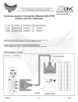
With HSLink, the distributed control architecture can become the figure 1.4.
User does not need one extra PC for Ethernet communication. User can
use one IPC to control the whole system.
Figure 1.4: HSLink as distributed PLC
16DI
16DI
16DI16DI 16DI

HSLink Introduction • 5
Ø Compare Figure 1.2, and Figure 1.4:
l The MPC (Monitor PC) is replace by PC with HSLink Master.
l The remote side PLC is replaced by HSLink slave I/O modules
l The RS485 or RS232 cable is replaced by simple Ethernet cable.
Ø HSLink as Remote Real-time DAQ
HSLink system gets many beneficial features as described on sections
before. Among those features, two are worthy of being particularly notified.
l High Speed
l Real time
To implement a DAQ application, the real-time characteristic is the most
important issue. With HSLink system, all I/O data are time-deterministic
refreshed. The sampling rate (or scan rate) is linearly dependent on the
number of slave I/O module used, ranges from 90µs (less than 3 modules)
to 2 ms (63 modules). These two features with HSLink’s born-nature
remoteness make HSLink very suitable for remote DAQ applications,
especially when real-time is concerned.
Figure 1.5: HSLink as real-time DAQ
16DI
16DI
16DI

6 • HSLink Introduction
Ø HSLink for SCADA system
HSLink is suitable for SCADA (supervisory control and data acquisition)
system. The character of HSLink in a SCADA system is DAQ hardware but
HMI toolkit. Users still need some SCADA software to accomplish the
completely SCADA function. The reason why HSLink is suitable for SCADA
is described below:
l HSLink is based on an open Architecture of PC.
l HSLink is able to support Mass I/O points
l HSLink is capable of real-time remote DAQ
The PC-based characteristic of HSLink system opens a highway to the “e”
world. User just set up his own HMI software on the PC where HSLink
master is installed. All I/O data is collected in a constant period from slave
I/O modules to master. Then, HMI could access these data through local
PCI-bus.
Figure 1.6: HSLink for SCADA
16DI
16DI
16DI

HSLink Introduction • 7
1.2 Specifications of HSLink System
The detail specifications of HSLink system are listed as following:
Ø Platform:
Computer hardware: Standard PC or IPC with PCI-Bus.
OS: Windows 95/98/2000/NT4.0 or Linux
Ø Programming tool:
Any Windows programming language that could integrates DLL
ISaGRAF (IEC1131-3 PLC standard).
Ø HSLink Master Interface Card:
PCI-7851: HSLink master controller card
PCI-7852: Dual HSLink master controller card
Ø Remoteness:
One master has two HSLink ports
One port can drive maximum 32 modules
One master can control maximum 63 slave I/O modules
Maximum wiring distance for each port: 200m (serial wiring)
Ø Wiring:
Connector: RJ45 (on both master controller and slave modules)
Cable: Shield Cat.5 100 Base/TX Ethernet cable
Ø Communication:
Multi-drop full-duplex RS-422 with transformer isolation scheme
Data Rate: 6Mbps
I/O Refreshing rate: 30.1 µs x numbers of slave I/O modules
Communication model: single-master / multi-slave
Communication method: command - response
CRC12 and dedicate protocol for eliminating any communication error

8 • HSLink Introduction
1.3 HSLink Series Products
Ø HSLink Master controller cards
There are two Master cards supported:
l PCI-7851: PCI bus, single HSLink master controller card.
l PCI-7852: PCI bus, dual HSLink master controller card.
At least one master controller card is necessary for HSLink system. With
PCI-7852, two master controllers are available on one card, therefore, it
supports two sets of HSLink systems.
Ø Slave I/O modules
A variety of HSLink slave I/O modules are available. Here are the lists.
Model
Numbers
Discrete
Input
Discrete
Output
Analog
Input
Analog
Output
Numbers
of Slave
HSL-DI32 32 2
HSL-DO32 32 2
HSL-R8DI16 16
8-CH
relay
1
HSL-DI16DO16
16 16 1
HSL-AI16 16-CH
1
HSL-AO4 4-CH 1
Table 1: Slave I/O modules
More slave I/O modules and intelligent master will be available soon.
Please always contact with ADLINK for newest HSLink series product
information.

HSLink Introduction • 9
1.4 HSLink Technical Information
1.4.1 HSLink Technology Brief
HSLink is a 1 -master-n-slave command-response communication system.
The one and only one master sends commands to slave I/O modules for
setting output values and requesting input information. Every slave
responses when receiving commands with slave number of its. The
response is either to set output according received values or to reply
requested input information to master.
The following graph personifiedly shows the working theory of HSLink
regarding how to set output values.
Figure 1.8: HSLink technology brief -1
The only one teacher (the master) sends message ”No.#, your output
values are ???” to all students (slave I/O modules), then the very student
(slave No.#) sets its output channels according values heard. The values
that master announced to slave modules are on the blackboard (RAM on
master cards), and can be easily modified by user.

10 • HSLink Introduction
And, the following graph shows working theory of gathering input
information.
Figure 1.9: HSLink technology brief-2
The only one teacher (the master) sends the message ”No.#, what’s your
newest input status” to all students, and the very student (slave NO.#) gives
his answer. Then, teacher writes the answer on the blackboard (RAM on
master cards). If someone (user’s AP) is interested in some slave’s newest
input status, he just looks up the blackboard. All input information is
presented there.
The two procedures above will take turn and repeat for every slave module.
And after a cycle, every slave module sets its newest output status and
master gathers every slave module’s newest input information in the
memory. We simulate the polling communication cycle by the following
personalized conversation of teacher and student:

HSLink Introduction • 11
Teacher: NO1, your output vales are %%, what’s your newest input status?
Student NO 1:My input status is ## (Teacher writes data on blackboard)
Teacher: NO2, your output vales are %%, what’s your newest input status?
Student NO 2:My input status is ## (Teacher writes data on blackboard)
……………(if 63 slave modules are
equipped)………………………
Teacher: NO63, your output vales are ##, what’s your newest input status?
Student NO 63: My input status is ## (Teacher writes data on blackboard)
(A polling cycle is completed)
(Repeat from NO1)
Figure 1.10: HSLink I/O polling cycle

12 • HSLink Introduction
1.4.2 Terminology of HSLink
In addition to input/output polling mechanism showed above, some syntax
related to HSLink should also be kept in mind.
HSLink Master: Master is the “teacher” character in Figure 1.9 & 1.10.
Master takes charge of giving commands, including output value
announcing and newest input status requesting.
Slave I/O Module: Slave I/O modules are the “student” characters in Figure
1.9 & 1.10. Slave I/O modules are passive components in HSLink system.
They just receive commands from master and then response - replying
newest input status or setting output values.
Polling Cycle: While communicating with slave I/O modules, the master
takes turns to set output for and gather input from every slave module. If all
slave modules are updated, we say that a polling cycle is completed. If only
the master is working normally, the polling cycle will infinitely repeat.
I/O Refreshing Rate: The “I/O Refreshing Rate” is defined as the time
needed to run a completed I/O updating cycle. Also, it could be defined as
the longest time needed for any digital I/O channel to get it’s newest status.
The refreshing rate is decided linearly by total number of slaves used in
individual HSLink system, but n o interference in any two HSLink systems at
the same PC or IPC.
Data Rate: This characteristic is quite ambiguous with I/O refreshing rate.
But they are totally different matters. Data rate is referring to speed of digital
signal transferred inside the wire cable. The unit of Data Rate is bps, Bits
Per Second, but unit of I/O refreshing rate is ms, mini-second.
1.4.3 System configurations
To establish a HSLink application, users need to know how to configure all
these HSLink cards and slave I/O modules. Here are some concepts
regarding configurations of HSLink system. For detail information, please
refer to individual chapter.
Master Card ID: The master card is a PCI bus add-on card with HSLink
master on it. In one IPC system, there may be more than one Master card. In
order to distinguish each master card, it is necessary to assign individual
master card with different Card ID.
/