ORBIT
SERVICE MANUAL
IInstructions

2
SPECIAL NOTES
S
P
E
C
I
A
L
N
O
T
E
S
W
A
R
N
I
N
G
SPECIAL NOTES
WARNING/CAUTION notices as used in this manual apply to hazards or unsafe practices which
could result in personal injury or property damage.
NOTICE
THE INFORMATION CONTAINED IN THIS DOCUMENT IS SUBJECT TO CHANGE WITHOUT NO-
TICE.
WHEELCHAIR USER
As a manufacturer of wheelchairs, Invacare endeavors to supply a wide variety of wheelchairs
to meet many needs of the end user. However, final selection of the type of wheelchair to be
used by an individual rests solely with the user and his/her healthcare professional capable of
making such a selection.
WHEELCHAIR TIE-DOWN RESTRAINTS AND SEAT POSITIONING STRAP
Invacare recommends that wheelchair users NOT be transported in vehicles of any kind while
in wheelchairs. As of this date, the Department of Transportation has not approved any tie-
down systems for transportation of a user while in a wheelchair, in a moving vehicle of any
type.
It is Invacare’s position that users of wheelchairs should be transferred into appropriate seat-
ing in vehicles for transportation and use be made of the restraints made available by the auto
industry. Invacare cannot and does not recommend any wheelchair transportation systems.
AS REGARDS RESTRAINTS - SEAT POSITIONING STRAP - IT IS THE OBLIGATION OF THE
DME DEALER, THERAPISTS AND OTHER HEALTHCARE PROFESSIONALS TO DETERMINE IF
A SEATING RESTRAINT IS REQUIRED TO ENSURE THE SAFE OPERATION OF THIS EQUIP-
MENT BY THE USER. SERIOUS INJURY CAN OCCUR IN THE EVENT OF A FALL FROM A WHEEL-
CHAIR.
TO HEALTHCARE PROFESSIONALS/ASSISTANTS:
The Invacare Orbit wheelchair MUST be operated by a HEALTHCARE professional or assistant
when in ANY tilt position.
ANTERIOR (FORWARD) TILT
Anterior (forward) tilt is a feature of this wheelchair designed for the USE OF A HEALTHCARE
PROFESSIONAL or ASSISTANT ONLY. Repositioning of the limit stops to obtain the anterior
(forward) tilt must NEVER be performed by the wheelchair user. When anterior (forward) tilt is
needed, it must ALWAYS be performed by a HEALTHCARE PROFESSIONAL or ASSISTANT. Make
sure the occupant of the wheelchair is properly positioned and always engage both wheel locks.
DO NOT operate the wheelchair when the seat frame is in the anterior (forward) tilt position
(seat frame is at approximately 10
o
forward tilt). Serious bodily injury may occur to the patient
and the assistant(s).
WARNING
DO NOT OPERATE THIS EQUIPMENT WITHOUT FIRST READING AND
UNDERSTANDING THIS MANUAL. IF YOU ARE UNABLE TO UNDERSTAND THE
WARNINGS, CAUTIONS, AND INSTRUCTIONS, CONTACT A HEALTHCARE
PROFESSIONAL, DEALER OR TECHNICAL PERSONNEL IF APPLICABLE BEFORE
ATTEMPTING TO USE THIS EQUIPMENT - OTHERWISE INJURY OR DAMAGE MAY
RESULT.
SAVE THESE INSTRUCTIONS

3
TABLE OF CONTENTS
TABLE OF CONTENTS
NOTE: The information in this service manual applies to the Tilt-in-Space and the non Tilt-in-Space Orbit
wheelchairs.
PROCEDURE 7 - REAR WHEELS ..................... 47
ADJUSTING THE WHEELBASE LENGTH ...... 47
ADJUSTING THE WHEELBASE WIDTH......... 48
ADJUSTING THE REAR WHEEL HEIGHT ...... 48
CONVERTING FROM A 12-INCH REAR
WHEEL TO A 20, 22, OR 24-INCH REAR
WHEEL OR VICE VERSA ............................ 49
T
A
B
L
E
O
F
C
O
N
T
E
N
T
S
SPECIAL NOTES ................................................2
SAFETY SUMMARY ............................................4
SPECIFICATIONS................................................ 5
PACKAGING ....................................................... 6
HANDLING.......................................................... 6
SAFETY INSPECTION CHECKLIST ..................... 7
TROUBLESHOOTING ......................................... 8
MAINTENANCE...................................................8
PROCEDURE 1 - GENERAL GUIDELINES ..........9
PROCEDURE 2 - DISASSEMBLY ...................... 10
REMOVING SEAT FRAME FROM BASE
FRAME.......................................................... 10
INSTALLING SEAT FRAME TO BASE
FRAME.......................................................... 10
PROCEDURE 3 - BACK..................................... 12
CHANGING THE BACK ANGLE ....................... 12
CORRESPONDING ARM ADJUSTMENT
TO THE BACK ANGLE .................................. 13
PROCEDURE 4 - SEAT ...................................... 14
ADJUSTING THE SEAT HEIGHT ...................... 14
ADJUSTING THE SEAT DEPTH ....................... 17
ADJUSTING THE PIVOT POINT OF THE
SEAT FRAME ................................................ 18
PROCEDURE 5 - CHANGING THE WIDTH......... 19
CHANGING THE WIDTH OF
THE TILT-IN-SPACE ORBIT............................ 19
CHANGING THE WIDTH OF
THE NON-TILT-IN-SPACE ORBIT ................... 39
ADDITIONAL WIDTH ADJUSTMENTS
FOR THE TILT-IN-SPACE AND NON-TILT
-IN-SPACE ORBIT WHEELCHAIRS ................ 45
PROCEDURE 6 - CASTERS .............................. 46
REPOSITIONING THE FRONT CASTER
ASSEMBLIES ................................................ 46
90
o
ADJUSTMENT OF THE CASTER
ASSEMBLIES ................................................ 46
CASTER HEADTUBE MOUNTING
ADJUSTMENTS............................................. 46
PROCEDURE 9 - ANTERIOR TILT/
SEAT TO FLOOR...............55
ANTERIOR TILT ................................................ 55
CHANGING THE SEAT TO FLOOR HEIGHT ...... 55
REAR WHEEL, CASTER SIZE, CASTER FORK,
AXLE BUSHING POSITION, PIVOT POINT
POSITION, AND HEADTUBE POSITION FOR:
15-1/2-INCH SEAT-TO-FLOOR HEIGHT .........56
16-1/2-INCH SEAT-TO-FLOOR HEIGHT .........56
17-1/2-INCH SEAT-TO-FLOOR HEIGHT .........59
18-1/2-INCH SEAT-TO-FLOOR HEIGHT .........61
19-1/2-INCH SEAT-TO-FLOOR HEIGHT .........64
20-1/2-INCH SEAT-TO-FLOOR HEIGHT .........67
21-1/2-INCH SEAT-TO-FLOOR HEIGHT .........69
PROCEDURE 10 - STABILITY ADJUSTMENTS . 70
ADJUSTMENTS FOR THE ADJUSTABLE
PIVOT POINT ....................................................71
ADJUSTMENTS FOR THE AXLE
MOUNTING POSITION ...................................... 72
ADJUSTMENTS FOR THE SEAT DEPTH .......... 73
ADJUSTMENTS FOR THE BACK ANGLE .........74
ADJUSTABLE SEAT HEIGHT ADJUSTMENTS .. 74
STABILITY ADJUSTMENT WITHOUT
A SEATING SYSTEM ..................................... 75
STABILITY ADJUSTMENT WITH A KSS
SEATING SYSTEM ........................................ 84
LIMITED WARRANTY ..................... BACK COVER
PROCEDURE 8 - TILT IN SPACE ....................... 51
REMOVING/INSTALLING/ADJUSTING THE
CABLE ASSEMBLY ..................................... 51
REMOVING/INSTALLING THE CABLE
ASSEMBLY FROM THE RELEASE PEDAL ... 52
REMOVING/INSTALLING THE TILT
MECHANISM(S)........................................... 53
REPOSITIONING THE RELEASE PEDAL ......54

4
SAFETY SUMMARY
SAFETY SUMMARY
S
A
F
E
T
Y
S
U
M
M
A
R
Y
STABILITY
WARNING
The seat height, seat depth, back angle, pivot point of seat frame, seating system, caster position, size and
position of the rear wheels, as well as the user condition directly relate to the stability of the wheelchair. Any
change to one (1) or any combination of the nine (9) may cause the wheelchair to decrease in stability. These
adjustments MUST be performed by a qualified technician.
OPERATING INFORMATION
WARNING
To determine and establish your particular safety limits, practice bending, reaching and transferring activities in several
combinations in the presence of a qualified healthcare professional BEFORE attempting active use of the wheelchair.
DO NOT attempt to reach objects if you have to move forward in the seat.
DO NOT attempt to reach objects if you have to pick them up from the floor by reaching down between your knees.
DO NOT lean over top of the back upholstery to reach objects from behind as this may cause the wheelchair to tip over.
DO NOT shift your weight or sitting position toward the direction you are reaching as the wheelchair may tip over.
DO NOT tip the wheelchair without assistance.
DO NOT use an escalator to move a wheelchair between floors. Serious bodily injury may occur.
DO NOT attempt to stop a moving wheelchair with the wheel locks. WHEEL LOCKS ARE NOT BRAKES.
Before attempting to transfer in or out of the wheelchair, every precaution should be taken to reduce the gap distance.
Turn both casters toward the object you are transferring onto. When transferring to and from the wheelchair, ALWAYS
ENGAGE BOTH WHEEL LOCKS.
DO NOT operate on roads, streets or highways.
DO NOT climb, go up or down ramps or traverse slopes greater than 9
o
.
DO NOT attempt to move up or down an incline with a water, ice or oil film.
DO NOT attempt to ride over curbs or obstacles. Doing so may cause your wheelchair to turn over and cause bodily
harm or damage to the wheelchair.
DO NOT use unauthorized parts, accessories, or adapters other than those authorized by Invacare.
DO NOT attempt to lift a wheelchair by lifting on any removable (detachable) parts. Lifting by means of any removable
(detachable) parts of a wheelchair may result in injury to the user or damage to the wheelchair.
DO NOT stand on the frame of the wheelchair.
Anti-tippers MUST BE attached at all times.
DO NOT use the footplate as a platform when getting in or out of the wheelchair.
ALWAYS wear your seat positioning strap. Inasmuch as the SEAT POSITIONING STRAP is an option on this wheelchair (You
may order with or without the seat positioning strap), Invacare strongly recommends ordering the SEAT POSITIONING
STRAP as an additional safeguard for the wheelchair user.
TIRE PRESSURE: DO NOT use your wheelchair unless it has the proper tire pressure (P.S.I.). DO NOT overinflate the tires.
Failure to follow these suggestions may cause the tire to explode and cause bodily harm. The recommended tire
pressure is listed on the side wall of the tire.
Replacement of a tire or tube MUST be performed by a qualified technician.
DO NOT use the release pedal of the tilt mechanism to gain leverage in tipping the wheelchair. The release pedal
was not designed to be used in this manner and may cause injury to the assistant and/or user or damage to the
wheelchair.
WEIGHT TRAINING: Invacare DOES NOT recommend the use of its wheelchairs as a weight training apparatus. Invacare
wheelchairs have NOT been designed or tested as a seat for any kind of weight training. If occupant uses said
wheelchair as a weight training apparatus, Invacare shall NOT be liable for bodily injury and the warranty will be voided
immediately.
WEIGHT LIMITATION: The Orbit wheelchair has a weight limitation of 150 lbs.

5
SPECIFICATIONS
ORBITORBIT
ORBITORBIT
ORBIT
Minimum Maximum
18.5-inches 24.5-inches
Short Frame: 35-inches 38-inches
Long Frame: 39-inches 42-inches
10 -16-inches
10 -16-inches
Aluminum, One-piece
15-1/2 to 21-1/2-inches
Adjustable Angle (80
O
to 110
O
), Fold Down
Fixed Height Anodized Cane w/Push Handles - 20-inch
"T" (Standard), Cantilever (Fixed Hgt. Anodized Cane w/Push
Handles Only) or Dual Point (Adjustable Height)
Swingaway Footrests and Elevating Legrests
Quick-Release or Permanent
Multi-Position
12, 20, 22 and 24-inch Composite Pneumatic or Pneumatic
with Flat Free Insert. 12-inch Urethane (Optional)
Aluminum, Plastic Coated and Projection
5-inch Aluminum or Composite Urethane
6 or 8-inch Composite Urethane, Pneumatic or Pneumatic w/Flat
Free Insert
Push-To-Lock, Wheel Lock Extensions, Hill Holder, Foot Activated
Wet Black, Red, Super Teal, Sunny Yellow, Chrome, Pink Pearl, Me-
tallic Blue, Deep Purple, Anthracite, Metallic Green, Cobalt Blue,
White, Lollipop Pink, Silver Vein, Passion Purple, Shocking Blue, Hot
Red, Grey Veil, Green Veil, Dark Purple, Gold Veil, Black w/Twilight
Sparkle, Black w/Red Sparkle, Black w/Green Sparkle, Black w/Blue
Sparkle, Black w/Gold Sparkle
32 lbs. - without front riggings
45 lbs.
S
P
E
C
I
F
I
C
A
T
I
O
N
S
SPECIFICATIONS
◆
NOTE: Invacare recommends that rear seat-to-floor height be AT LEAST 3/8-inch shorter than front
seat-to-floor height. Otherwise a forward seat dump can occur. The rear seat-to-floor heights are based
on pneumatic tires or pneumatic tires with flat free inserts. If wheelchair is equipped with urethane tires,
subtract 1/4-inch from the measurements listed above. All heights are approximate to +1/4-inch due to
tire wear and air pressure. The front seat-to-floor heights are approximate to +1/4-inch.
PHYSICAL SPECIFICATIONS
Overall Width
(in one (1) inch increments):
Overall Depth (w/o front riggings):
Seat Width
(in one [1] inch increments):
Seat Depth
(in one [1] inch increments):
Frame Type:
◆ ◆
◆ ◆
◆ Seat-to-Floor Range:
Back Style and Height:
Arm Styles:
Footrest:
Rear Axle:
Rear Axle Mounting Plates:
Rear Wheels:
Handrims:
Caster Size:
Wheel Locks:
Frame Colors:
Weight (Approx.):
Shipping Weight (Approx.):

6
UNPACKING
1. Check for any obvious damage to the carton or
its contents. If damage is evident, notify your
Dealer/Carrier.
2. Remove all loose packing from the carton.
3. Carefully remove all components from the
carton.
NOTE: Unless the Orbit
is to be assembled
immediately, retain cartons and packing materials
for use in storing the wheelchair until assembly is
required.
HANDLING
INSPECTION
1. Examine exterior of the Orbit for nicks, dents,
scratches or other damages. Inspect all compo-
nents. If damage is evident, notify your Dealer/
Carrier.
STORAGE
1. Store the packaged/repackaged Orbit in a dry
area.
2. DO NOT place other objects on top of the pack-
aged/repackaged wheelchair.
PACKAGING/HANDLING
PACKAGING
Accessory
Cartons
Seat
Frame
Base
Frame
Rear
Wheels
P
A
C
K
A
G
I
N
G
H
A
N
D
L
I
N
G

7
SAFETY INSPECTION CHECKLIST
SAFETY INSPECTION CHECK LIST
NOTE: Twice a year take your wheelchair to a qualified technician for a thorough inspection and servicing.
Regular cleaning will reveal loose or worn parts and enhance the smooth operation of your wheelchair. To
operate properly and safely, your wheelchair must be cared for just like any other vehicle. Routine mainte-
nance will extend the life and efficiency of your wheelchair.
Initial adjustments should be made to suit your personal body structure and preference. Thereafter follow
these maintenance procedures:
ITEM INITIALLY INSPECT/ INSPECT/ INSPECT/
ADJUST ADJUST ADJUST
WEEKLY MONTHLY PERIODICALLY
GENERAL
Wheelchair rolls straight (no excessive drag or
pull to one side). X X
SEAT AND BACK (PROCEDURES 4* and 5*)
Inspect back mounting plate attaching hardware
is securely tightened. X X
Inspect back fold down mechanisms to ensure
they securely latch. X X
REAR WHEELS (PROCEDURE 7*)
No excessive side movement or binding when
lifted and spun. X X
Quick-release axle locks properly. X X
FRONT CASTER (PROCEDURE 6*)
Inspect wheel/fork assembly for proper tension X X
by spinning caster; caster should come to a
gradual stop.
Loosen/tighten locknut if wheel wobbles X X X
noticeably or binds to a stop.
Wheel bearings are clean and free of moisture. X X
CAUTION: As with any vehicle, the wheels and
tires should be checked periodically for cracks
and wear, and should be replaced.
TIRES (PROCEDURES 5* and 6*)
Inspect for flat spots and wear. X X
If pneumatic tires, check for proper inflation. X X
CAUTION: As with any vehicle, the wheels and
tires should be checked periodically for cracks
and wear, and should be replaced when.
WHEEL LOCKS (PROCEDURE 8*)
Do not interfere with tires when rolling. X X
Pivot points free of wear and looseness. X X
Wheel locks easy to engage. X X
CLEANING
Clean upholstery and armrests. X X
S
A
F
E
T
Y
I
N
S
P
E
C
T
I
O
N
NOTE: * Refer to the Owner's Manual, part number 1073955, for these procedures.

8
TROUBLESHOOTING
CHAIR CHAIR SLUGGISH CASTERS SQUEAKS LOOSENESS CHAIR SOLUTIONS
VEERS VEERS TURN OR FLUTTERS AND IN CHAIR 3 WHEELS
RIGHT LEFT PERFORMANCE RATTLES
XX X X XIf pneumatic, check tires
for correct and equal
pressure.
XXXX Check for loose stem
nuts and bolts.
XX X Check that both casters
contact the ground at
the same time.
4. Periodically check the back fold down mechanisms
to ensure that they lock the back securely in place.
Disassemble and clean if necessary. Refer to RE-
PLACING THE LOCKING MECHANISM IN THE
BACK CANE in PROCEDURE 4 of the owner's
manual, part number 1073955.
WARNING
Do not use the wheelchair unless it has the
proper tire pressure (P.S.I.). DO NOT overinflate
the tires. Failure to follow these suggestions
may cause the tire to explode and cause
bodily harm. The recommended tire pressure
is listed on the side wall of the tire.
5. If tires are pneumatic, recommended tire pressure
is listed on the side wall of the tire.
6. The wheels and tires should be checked periodi-
cally for cracks and wear, and should be replaced
when necessary at your authorized dealer or by a
qualified technician.
7. Periodically check handrims to ensure they are
secured to the rear wheels. Refer to HANDRIM
REPLACEMENT in PROCEDURE 7 of the
owner's manual, part number 1073955.
8. Periodically adjust wheel locks in correlation to
tire wear. Refer to ADJUSTING THE WHEEL
LOCKS in PROCEDURE 8 of the owner's manual,
part number 1073955.
9. Periodically check front caster wheel bearings to
make sure they are clean and free from moisture.
Use a Teflon lubricant if necessary.
10. Check Upholstery for sagging, rips or tears.
MAINTENANCE SAFETY
PRECAUTIONS
WARNING
After adjustments and before use, make sure
all attaching hardware is securely tightened.
CAUTION
DO NOT overtighten hardware attaching to
the frame. This could cause damage to the
frame tubing.
SUGGESTED MAINTENANCE
PROCEDURES
1. Before using your Orbit, make sure all nuts and
bolts are tight. Check all parts for damage or wear
and replace. Check all parts for proper
adjustment.
2. Keep quick-release axles free of dirt and lint to
ensure positive locking and proper operation. Re-
fer to ADJUSTING THE QUICK-RELEASE AXLE
in PROCEDURE 7 of the owner's manual, part
number 1073955.
3. Oil quick-release axles at least once (1) a month
(3-in-1 oil
®
or equivalent).
MAINTENANCE
TROUBLESHOOTING/MAINTENANCE
M
A
I
N
T
E
N
A
N
C
E
T
R
O
U
B
L
E
S
H
O
O
T
I
N
G
3-in-1 oil - Registered trademark of American
Home Products Corporation.

9
GENERAL GUIDELINES PROCEDURE 1
PROCEDURE 1 - GENERAL GUIDELINES
G
E
N
E
R
A
L
G
U
I
D
E
L
I
N
E
S
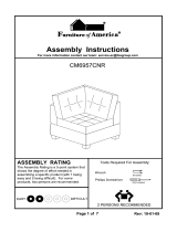
GENERAL WARNINGS
These adjustments MUST be performed by a qualified technician.
After adjustments and before use, make sure all attaching hardware is securely tightened.
CAUTION
DO NOT overtighten hardware attaching to the frame. This could cause damage to frame
tubing.
SPECIFIC WARNINGS - STABILITY
The seat height, seat depth, back angle, pivot point of seat frame, seating system, caster
position, size and position of the rear wheels, as well as the user condition directly relate to
the stability of the wheelchair. Any change to one (1) or any combination of the nine (9) may
cause the wheelchair to decrease in stability. Refer to STABILITY ADJUSTMENTS in
PROCEDURE 10 of this manual.
Seating System
User Condition
Caster Position
Back Angle
Seat Depth
Size and Position of
the Rear Wheels
FIGURE 1 - GENERAL GUIDELINES
Seat Height
Pivot Point of Seat Frame

10
PROCEDURE 2 DISASSEMBLY
D
I
S
A
S
S
E
M
B
L
Y
9. Fold down the back canes. Refer to FOLDING/UN-
FOLDING THE BACK CANES in PROCEDURE 4
of the Owner's Manual, part number 1073955.
10. Remove rear wheels. Refer to REMOVING/IN-
STALLING THE REAR WHEELS in PROCEDURE
7 of the Owner's Manual, part number 1073955.
INSTALLING THE SEAT FRAME
TO THE BASE FRAME (FIGURE 1)
1. Unfold back canes. Refer to FOLDING/UNFOLD-
ING THE BACK CANES in PROCEDURE 4 of this
manual.
2. If so equipped, unfold cantilever arms. Refer to US-
ING/INSTALLING/HEIGHT ADJUSTMENT/COR-
RESPONDING ARM ADJUSTMENT TO BACK
ANGLE OF THE CANTILEVER ARMS in PROCE-
DURE 3 of the Owner's Manual, part number
1073955.
3. If so equipped, install the T-arms. Refer to REMOV-
ING/INSTALLING THE T-ARMS in PROCEDURE
3 of the Owner's Manual, part number 1073955.
4. Install rear wheels. Refer to REMOVING/INSTALL-
ING REAR WHEELS in PROCEDURE 7 of the
Owner's Manual, part number 1073955.
5. Turn the plungers located on the underside of the
base frame plate until an audible click is heard. See
DETAIL "A".
6. Visually inspect the base frame plate to ensure the
locking buttons protrude all the way through the plate.
7. Place seat frame plate on base frame plate depress-
ing the locking buttons.
8. Slide seat frame rearward.
WARNING
Ensure both sides of seat frame plate are under-
neath the locking channels of the base frame
plate and the seat frame is securely locked in
place before using the wheelchair, otherwise in-
jury may result.
9. With both sides of seat frame plate underneath the
locking channels of the base frame plate, continue to
slide until an audible click from both locking buttons is
heard.
NOTE: If an audible click is not heard from both locking
buttons, wiggle seat frame plate back and forth until an
audible click is heard. This will ensure the seat frame is
locked into position.
This Procedure Includes the Following:
Removing the Seat Frame from the Base Frame
Installing the Seat Frame to the Base Frame
WARNING
After adjustments and BEFORE use, make sure all
attaching hardware is securely tightened.
REMOVING THE SEAT FRAME
FROM THE BASE FRAME
(FIGURE 1)
WARNING
Invacare recommends that wheelchair
users NOT be transported in vehicles of any kind
while in wheelchairs. As of this date, the Depart-
ment of Transportation has not approved any tie-
down systems for transportation of a user while in
a wheelchair, in a moving vehicle of any type.
1. If necessary, return the wheelchair to 0
o
tilt. Refer to
ENGAGING THE TILT-IN-SPACE in PROCE-
DURE 9 of the Owner's Manual, part number 1073955.
2. Remove occupant from wheelchair.
3. Pull down and turn plungers located on underside of
base frame plate. See DETAIL "A".
4. Push in on the tip of the quick release pin located on
underside of base frame plate and pull out of seat/
base frame plate assembly. See DETAIL "A".
5. To disengage the seat frame from the base frame,
push/pull the seat frame forward.
NOTE: If a seating system is being used on the wheel-
chair, refer to the seating system Owner's Manual for in-
stallation and removal of the seating system.
6. If so equipped, remove the existing seating system
from the wheelchair.
7. If so equipped, fold cantilever arms. Refer to USING/
INSTALLING/HEIGHT ADJUSTMENT/CORRE-
SPONDING ARM ADJUSTMENT TO BACK
ANGLE OF THE CANTILEVER ARMS in PROCE-
DURE 3 of the Owner's Manual, part number
1073955.
8. If so equipped, remove the T-arms. Refer to REMOV-
ING/INSTALLING THE T-ARMS in PROCEDURE
3 of the Owner's Manual, part number 1073955.

11
FIGURE 1 - REMOVING/INSTALLING THE SEAT FRAME FROM/TO THE BASE FRAME
SEAT FRAME AND BASE FRAME DISASSEMBLED
Locking
Channel
SEAT FRAMEBASE FRAME
SECTIONAL OF SEAT FRAME AND BASE FRAME
ASSEMBLED
(WITHOUT SEATING SYSTEM)
Seat Frame
Plate
Base Frame
Plate
Locking
Button
Locking Buttons
Engage Here
Seat Frame
Plate
Locking Buttons
Engaged
Locking
Channels
DETAIL "A" - SIDE VIEW
11. Pull down on quick-release pin to ensure positive
lock.
NOTE: If a seating system is being used on the wheel-
chair, refer to the seating system Owner's Manual for
installation and removal of the seating system.
12. Reinstall the existing seating system onto the
wheelchair, if so equipped.
WW
WW
W
ARNINGARNING
ARNINGARNING
ARNING
Make sure the locking pins of the quick-release
pin are fully released BEFORE operating the wheel-
chair.
The locking pins MUST be protruding past the top
of the seat plate assembly for a positive lock.
Keep locking pins clean.
10. Push in on the tip of the quick-release pin and rein-
stall in the seat/base frame plate assembly. See DE-
TAIL "A".
Crossmember
Crossmember
Seat Frame
Plate
Base Frame Plate
Plunger
Quick-Release
Pin
Locking
Pins
Quick-Release
Pin
Top of
Seat Frame
Plate
Base Frame
Plate
Tip
Locking
Button
D
I
S
A
S
S
E
M
B
L
Y
PROCEDURE 2DISASSEMBLY

12
BACKPROCEDURE 3
CHANGING THE BACK ANGLE
(FIGURES 1 AND 2)
NOTE: Refer to Procedure 1 - General Guidelines
which include GENERAL and SPECIFIC WARNINGS
concerning wheelchair stability.
1. Loosen, but do not remove the front hex screw
that secures the back angle plate to the wheel-
chair frame.
2. Remove the rear hex screw, washer and locknut
that secure the back angle plates to the wheel-
chair frame.
This Procedure Includes the Following:
Changing the Back Angle
Corresponding Arm Adjustment to Back Angle
5. If the wheelchair is equipped with cantilever arms
refer to CORRESPONDING ARM ADJUSTMENT
TO BACK ANGLE OF THE CANTILEVER ARMS
in this PROCEDURE of the manual.
NOTE: If the wheelchair has become less stable
after changing the back angle, reposition the rear
wheels. Refer to ADJUSTING THE WHEELBASE
LENGTH in PROCEDURE 7 of this manual.
BB
BB
B
AA
AA
A
CC
CC
C
KK
KK
K
105105
105105
105
OO
OO
O
110110
110110
110
OO
OO
O
FIGURE 2 - BACK ANGLE PLATE MOUNTING
HOLES FOR CORRESPONDING BACK ANGLES
Back Plate
Back Plate
Back Plate Back Plate
9595
9595
95
OO
OO
O
100100
100100
100
OO
OO
O
Back Plate
8585
8585
85
OO
OO
O
9090
9090
90
OO
OO
O
Back Plate
8080
8080
80
OO
OO
O
Back Plate
FIGURE 1 - CHANGING THE BACK ANGLE
Locknut
Wheelchair
Frame
Rear Hex
Screw
Back Angle
Plate
Front Hex Screw
(Loosen, but do not
Remove)
Coved
Washers
Washer
3. Refer to FIGURE 2 to determine the mounting
hole in the back angle plates for the necessary
back angle.
4. Reinstall the rear hex screw, washer and se-
curely tighten with locknut.
B
A
C
K

13
FIGURE 3 - CORRESPONDING ARM ADJUSTMENT TO BACK ANGLE OF THE CANTILEVER ARM
8080
8080
80
OO
OO
O
Back
Plate
Arm
Plate
8585
8585
85
OO
OO
O
Back
Plate
Arm
Plate
9090
9090
90
OO
OO
O
Back
Plate
Arm
Plate
9595
9595
95
OO
OO
O
Back
Plate
Arm
Plate
100100
100100
100
OO
OO
O
Back
Plate
Arm
Plate
105105
105105
105
OO
OO
O
AND 110AND 110
AND 110AND 110
AND 110
OO
OO
O
Back
Plate
Arm
Plate
3. Refer to FIGURE 3 to determine the mounting
hole in the adjustment plate that will be used to
correspond to the back angle.
NOTE: Back angles of 105
o
and 110
o
will use the
same arm adjustment plate mounting holes.
4. Securely tighten the locking pin and washer to
the adjustment plate with a locknut.
5. Repeat STEPS 1-4 for the opposite side, if nec-
essary.
CORRESPONDING ARM
ADJUSTMENT TO BACK ANGLE
(FIGURE 3)
NOTE: This adjustment is recommended if the back
angle has been changed to keep arm parallel to
the ground/floor.
1. Flip the cantilever arm up and out of the way.
2. Remove the locknut that secures the locking pin
to the adjustment plate. See FIGURE 3-
DETAIL "A".
B
A
C
K
Adjustment
Plate
Locknut
Washer
Locking Pin
DETAIL "A"
PROCEDURE 3BACK
B
A
C
K

14
PROCEDURE 4 SEAT
This Procedure Includes the Following:
Adjusting the Seat Height
Adjusting the Seat Depth
Adjusting the Pivot Point of the Seat Frame
S
E
A
T
NOTE: If adjusting to or from the LOW position, the angle
of the mounting bracket changes, continue with next
NOTE. If changing from middle to high position or vice
versa, proceed to STEP 13.
NOTE: Note the position of the top front crossmember
for proper reinstallation of the NEW top front
crossmember. FIGURE 1 - DETAIL "A" shows the rela-
tionship between the adjustable height pivot tubes and
the angle of the mounting bracket. This relationship must
be maintained for your desired height adjustment, other-
wise, 0
o
tilt minimum and 45
o
tilt maximum will not be
obtainable.
8. Remove the mounting screw(s) and locknuts that
secure the lower portion of the tilt mechanism(s) to
the mounting bracket(s) of the top front crossmember.
Place tilt mechanism(s) on ground/floor.
9. Remove the mounting screws and washers that se-
cure the top front crossmember to the base frame.
10. Rotate the crossmember 180
o
to obtain the proper
orientation (up or down) of the mounting bracket to
match desired seat height. See FIGURE 1 - DETAIL
"A".
11. Reinstall crossmember and secure with the two (2)
mounting screws and washers. Torque 75-80 inch
pounds.
12. Secure the lower portion of tilt mechanism(s) to the
mounting bracket(s) with the mounting screw(s) and
locknut(s).
13. Activate the tilt mechanism by stepping on the re-
lease pedal.
14. Extend or retract the top portion of the tilt
mechanism(s) by hand until the mounting hole is
aligned with the mounting bracket on the underside
of the seat plate assembly.
15 Secure the upper portion of the tilt mechanism(s) to
the underside of the seat plate assembly with the
mounting screw(s), washer, spacers, and locknut(s).
Securely tighten.
NOTE: Washer and spacers are found only on the single
tilt mechanism.
16. Reinstall the seat frame onto the base frame. Refer
to DISASSEMBLY in PROCEDURE 2 of this manual.
ADJUSTING THE SEAT HEIGHT
NOTE: Refer to Procedure 1 - General Guidelines
which include GENERAL and SPECIFIC WARNINGS
concerning wheelchair stability.
Tilt-in-Space Orbit (FIGURE 1)
1. Determine your desired seat-to-floor height. Refer
to SEAT-TO-FLOOR HEIGHT in PROCEDURE 9
of this manual.
NOTE: Ensure you have the correct rear wheels, caster
size, caster forks, and axle bushing position determined
in STEP 1.
2. Remove occupant from wheelchair.
3. Remove the seat frame from the base frame. Refer
to DISASSEMBLY in PROCEDURE 2 of this manual.
4. Remove the mounting screw(s), washer, spacers,
and locknut(s) that secure the upper portion of the tilt
mechanism(s) to the seat plate assembly.
NOTE: Washer and spacers are found only on the single
tilt mechanism.
NOTE: Note the position of the adjustable height pivot
tube to maintain the same seat height. See FIGURE 1-
DETAIL "A"
.
5. Remove the mounting screws and locknuts that se-
cures the seat plate assembly to the base frame.
6. Adjust seat to one (1) of three (3) positions: LOW
position, MIDDLE position, or HIGH position. See
FIGURE 1 - DETAIL "A".
7. Secure the seat plate assembly to the base frame
with the mounting screws and locknuts. Securely
tighten.

15
DETAIL "A"
MIDDLE POSITION
One (1) hole showing
on the adjustable height
pivot tube
HIGH POSITION
Two (2) holes showing
on the adjustable height
pivot tube
Adjustable Height
Pivot Tube
Mounting
Bracket
(Down)
Mounting
Bracket
(Down)
No Holes
Showing
One (1) Hole
Showing
Adjustable Height
Pivot Tube
Adjustable Height
Pivot Tube
Top Front
Crossmember
Top Front
Crossmember
Top Front
Crossmember
LOW POSITION
Zero holes showing
on the adjustable height
pivot tube
Two (2) Holes
Showing
Mounting
Bracket
(Up)
S
E
A
T
NOTE: ONLY the single tilt mechanism is shown for clarity. The dual tilt mechanism removes in the same manner.
NOTE: DETAIL "A" and FIGURE 1 depict only one mounting bracket. The relationship between the
mounting bracket and the adjustable height pivot tubes is the same for two (2) mounting brackets, which
is required on the larger seat frames.
NOTE: Hardware for the lower portion of the tilt mechanism and top front crossmember ONLY need to
be removed if changing to or from the LOW position.
Mounting
Bracket
(STEP 8)
FIGURE 1 - ADJUSTING THE SEAT HEIGHT - TILT-IN-SPACE ORBIT
Locknut
(STEPS 4, 15)
Washer
(STEPS 4, 15)
Spacer
(STEPS 4, 15)
Upper Portion of
Tilt Mechanism
(STEP 4)
Lower Portion of
Tilt Mechanism
(STEP 8)
Mounting Screw
(STEPS 9, 11)
Washer
(STEPS 9, 11)
Tilt Mechanism
Top Front
Crossmember
(STEPS 8, 9)
Seat Plate
Assembly
(STEPS 5, 7)
Mounting Screw
(STEPS 4, 15)
Locknuts
(STEPS 5, 7)
Base Frame
Mounting Screw
(STEPS 5, 7)
Mounting Screw
(STEP 8, 12)
Mounting Screw
(STEPS 9,11)
Locknut
(STEPS
8, 12)
PROCEDURE 4SEAT

16
Non-Tilt-in-Space Orbit (FIGURE 2)
NOTE: Refer to Procedure 1 - General Guidelines
which include GENERAL and SPECIFIC WARNINGS
concerning wheelchair stability.
1. Determine your desired seat-to-floor height. Re-
fer to SEAT-TO-FLOOR HEIGHT in PROCE-
DURE 9 of this manual.
NOTE: Ensure you have the correct rear wheels, caster
size, caster forks, and axle bushing position determined
in STEP 1.
2. Remove occupant from wheelchair.
3. Remove the seat frame from the base frame.
Refer to DISASSEMBLY in PROCEDURE 2 of
this manual.
4. Remove the mounting screws and locknuts that
secure the lower portion of the non-tilt rods to the
top front crossmember.
5. Remove the mounting screws and locknuts that
secures the seat plate assembly to the base frame.
FIGURE 2 - ADJUSTING THE SEAT HEIGHT - NON-TILT-IN-SPACE ORBIT
6. Adjust seat plate assembly to one (1) of three (3)
positions: LOW position, MIDDLE position, or
HIGH position. Refer to FIGURE 2.
7. Secure the seat plate assembly to the base frame
with the mounting screws and locknuts. Securely
tighten.
WARNING
The non-tilt rods and the seat plate assembly
MUST be adjusted to the exact same mount-
ing position (i.e. - HIGH - HIGH; MIDDLE -
MIDDLE; or LOW - LOW). The seat plate assem-
bly MUST remain level - otherwise, injury may
result.
8. Adjust the non-tilt rods to the corresponding seat
position: LOW position, MIDDLE position, or HIGH
position. Refer to FIGURE 2.
9. Secure the lower portion of the non-tilt rods to the
mounting brackets with the existing mounting
screws and locknuts. Securely tighten.
10. Reinstall the seat frame onto the base frame.
Refer to DISASSEMBLY in PROCEDURE 2 of
this manual.
Non-Tilt Rods
(STEPS 4,8,9)
Seat Plate
Assembly
(STEPS 5,6)
Base Frame
(STEP 5)
S
E
A
T
Mounting
Screw
(STEPS 5,7)
Locknut
(STEPS 5,7)
Top Front
Crossmember
Mounting
Screw
(STEPS 4,9)
Mounting
Screw
(STEPS 5,7,9)
Locknut
(STEPS 4,9)
LOW
position
MIDDLE
position
HIGH
position
LOW position
MIDDLE position
HIGH position
Seat Plate
Mounting
Screw
(STEPS 4,9)
Non-Tilt Rods
PROCEDURE 4 SEAT

17
S
E
A
T
PROCEDURE 4SEAT
ADJUSTING THE SEAT DEPTH
(FIGURES 3, 4 AND 5)
NOTE: Refer to Procedure 1 - General Guidelines
which include GENERAL and SPECIFIC WARNINGS
concerning wheelchair stability.
1. Determine the necessary back position for the
desired seat depth. Refer to FIGURES 4 AND 5
for proper back positioning.
2. If necessary, remove the rear wheels from the
wheelchair. Refer to REMOVING/INSTALLING
THE REAR WHEEL in PROCEDURE 7 of the
owner's manual, part number 1073955.
NOTE: Note the back angle before removing for
proper reinstallation. If a change in the back angle
is desired, refer to CHANGING THE BACK ANGLE
in PROCEDURE 3 of this manual.
3. Remove the two (2) mounting screws, washers
and locknuts that secure the two (2) back angle
plates to the wheelchair frame. Repeat for op-
posite side (FIGURE 3).
4. Align the mounting holes in the back angle plates
with the mounting holes in the rear seat rail de-
termined in STEP 1.
5. Secure the back angle plates to the wheelchair
frame, at the angle noted previously, with the
two (2) mounting screws, washers and locknuts.
Repeat for opposite side. Securely tighten.
NOTE: Make sure the back angle plates are at the
same angle BEFORE using the wheelchair.
BACK POSITION FOR 16-INCH SEAT DEPTH
Hole for
Front Riggings
18 17 16 15 14 13 12 11 10
BACK POSITION FOR 15-INCH SEAT DEPTH
Rear of
Seat
Rail
18 17 16 15 14 13 12 11 10
18 17 16 15 14 13 12 11 10
BACK POSITION FOR 14-INCH SEAT DEPTH
BACK POSITION FOR 13-INCH SEAT DEPTH
Rear of
Seat
Rail
WARNING:
Never Use These Mounting
Holes for Seat Depth
Front of
Seat
Rail
Front of
Seat
Rail
Rear of
Seat
Rail
FIGURE 4 - ADJUSTING THE SEAT DEPTH
(BACK PLATE POSITION)
Hole for
Front Riggings
18 17 16 15 14 13 12 11 10
Rear of
Seat
Rail
Front
of
Seat
Rail
Hole for
Front Riggings
Hole for
Front Riggings
WARNING:
Never Use These Mounting
Holes for Seat Depth
WARNING:
Never Use These Mounting
Holes for Seat Depth
Front
of
Seat
Rail
WARNING:
Never Use These Mount-
ing Holes for Seat Depth
FIGURE 3 - ADJUSTING THE SEAT DEPTH
Back Angle
Plate
Washer
Locknut
Mounting
Screws
Wheelchair
Frame
Back Angle
Plate

18
18 17 16 15 14 13 12 11 10
BACK POSITION FOR 10-INCH SEAT DEPTH
Hole for
Front Riggings
18 17 16 15 14 13 12 11 10
BACK POSITION FOR 11-INCH SEAT DEPTH
18 17 16 15 14 13 12 11 10
BACK POSITION FOR 12-INCH SEAT DEPTH
Hole for
Front Riggings
PROCEDURE 4 SEAT
S
E
A
T
Rear of
Seat
Rail
Front of
Seat
Rail
Rear of
Seat
Rail
Front of
Seat
Rail
Rear of
Seat
Rail
Front of
Seat
Rail
Hole for
Front Riggings
ADJUSTING THE PIVOT POINT OF
THE SEAT FRAME (FIGURES 6, 7)
NOTE: Refer to Procedure 1 - General Guidelines
which include GENERAL and SPECIFIC WARNINGS
concerning wheelchair stability.
1. Remove the existing seating system from the
wheelchair, if so equipped.
NOTE: Refer to your particular seating system
manufacturer's Owner's Manual for installation and
removal of the seating system.
2. Remove the four (4) mounting screws and wash-
ers that secure the seat plate assembly to the
seat rails (FIGURE 7).
FIGURE 5 - ADJUSTING THE SEAT DEPTH
(BACK PLATE POSITION)
WARNING:
Never Use These Mounting
Holes for Seat Depth
WARNING:
Never Use These Mounting
Holes for Seat Depth
WARNING:
Never Use These Mounting
Holes for Seat Depth
WARNING
For FRONT crossmember use ONLY mounting
holes one (1) through five (5). For REAR
crossmember use ONLY mounting holes eight
(8) through twelve (12). See FIGURE 6.
3. Position the seat plate assembly at the mount-
ing holes for the desired pivot point. Refer to
FIGURE 6 for acceptable mounting positions.
12 11 10 9 8 5 4 3 2 1
Front
Crossmember
of Seat Plate
Mounting
Hole for
Bilateral
Platform
Mounting Hole for Front Riggings
Rear
Crossmember
of Seat Plate
XX XX
ACCEPTABLE MOUNTING COMBINATIONS
Front Crossmember 1 2 3 4 5
and and and and and
Rear Crossmember 8 9 10 11 12
FIGURE 6 - ACCEPTABLE MOUNTING
HOLES FOR THE ADJUSTABLE PIVOT
POINT
4. Secure seat plate assembly with the four (4) mount-
ing screws and washers to the seat rails at the
determined position in STEP 3 (FIGURE 7).
5. Reinstall the seating system, if so equipped.
Washers
Seat Plate
Assembly
Seat
Rail
Back
Mounting
Plates
Seat
Rail
Mounting Screws
FIGURE 7 - ADJUSTING THE PIVOT POINT
OF THE SEAT FRAME

19
PROCEDURE 5CHANGING THE WIDTH
This Procedure Includes the Following:
Changing the Width of the Tilt-in-Space Orbit Additional Width Adjustments for the
Changing the Width of the Non Tilt-in-Space Orbit Tilt-in-Space and the Non-Tilt-in-Space Orbit
C
H
A
N
G
I
N
G
T
H
E
W
I
D
T
H
B
A
S
E
F
R
A
M
E
NOTE: The combinations of seat frame and base frame enclosed in the outlined box will require two (2) tilt mecha-
nisms.
SEAT FRAME
10 11 12 13 14 15 16
10 YES YES YES NO NO NO NO
11 YES YES YES YES NO NO NO
12 YES YES YES YES YES NO NO
13 YES YES YES YES YES YES NO
14 YES YES YES YES YES YES YES
15 YES YES YES YES YES YES YES
16 YES YES YES YES YES YES YES
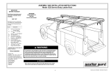
STEP 2: Review the chart below to determine the allowable seat frame width and base frame width com-
binations.
WARNING
The seat frame width MUST NOT EXCEED the base frame width by more than 2-inches. Any seat width
greater than 2-inch in relation to the base frame WILL cause the wheelchair to decrease in stability.
These adjustments MUST be performed by a qualified technician.
NOTE: The seat frame and base frame widths are measured in inches.
CHANGING THE WIDTH OF THE TILT-IN-SPACE ORBIT
NOTE: The Orbit wheelchair has a unique feature enabling the user to position a wider seat frame onto a much
narrower base frame or vice versa. The following steps were developed to provide assistance in successfully
determining and changing the orbit into the desired configuration.
STEP 1: Carefully review the following charts and understand the width sizes for the Orbit.
SEAT FRAME WIDTHS
NOTE: SMALL seat frames require one (1) tilt
mechanism.
NOTE: LARGE seat frames require two (2) tilt mechanims.
SMALL
10-INCHES
11-INCHES
12-INCHES
13-INCHES
LARGE
14-INCHES
15-INCHES
16-INCHES
BASE FRAME WIDTHS
NOTE: The number of tilt mechanisms on the base
frame will be determined by the seat width.
10-INCHES
11-INCHES
12-INCHES
13-INCHES
14-INCHES
15-INCHES
16-INCHES
ALLOWABLE SEAT FRAME AND BASE FRAME WIDTH COMBINATIONS

20
STEP 3: Determine the statement that corresponds with your desired change. Then, within that
section, determine if a change in the base frame width is desired. Continue to follow
that row all the way over to the right column. This will tell you which sections in this
procedure need to be followed to complete your width change.
Changing the width Perform the following
of the base frame? Section(s)
YES NO
❏ ❏ A
❏❏ A, D, F
I Changing the seat frame width remaining within the limitations of the small seat frame range
(10-13-inches).
Refer to SECTIONS D and F - Small Seat Frame (Single tilt mechanism)
Refer to SECTIONS E and F - Large Seat Frame (Dual tilt mechanisms)
Changing the width Perform the following
of the base frame? Section(s)
YES NO
❏❏ B
❏❏ C, F
Changing the width Perform the following
of the base frame? Section(s)
YES NO
❏❏ A
❏❏ A, E, F
PROCEDURE 5 CHANGING THE WIDTH
II Changing the seat frame width from small seat frame (10-13-inches) to large seat frame (14-16-
inches) or vice versa.
IV Only changing the base frame width and not changing the seat frame width.
C
H
A
N
G
I
N
G
T
H
E
W
I
D
T
H
✓
III Changing the seat frame width remaining within the limitations of the large seat frame range
(14-16-inches).
✓
✓
✓
✓
✓
Page is loading ...
Page is loading ...
Page is loading ...
Page is loading ...
Page is loading ...
Page is loading ...
Page is loading ...
Page is loading ...
Page is loading ...
Page is loading ...
Page is loading ...
Page is loading ...
Page is loading ...
Page is loading ...
Page is loading ...
Page is loading ...
Page is loading ...
Page is loading ...
Page is loading ...
Page is loading ...
Page is loading ...
Page is loading ...
Page is loading ...
Page is loading ...
Page is loading ...
Page is loading ...
Page is loading ...
Page is loading ...
Page is loading ...
Page is loading ...
Page is loading ...
Page is loading ...
Page is loading ...
Page is loading ...
Page is loading ...
Page is loading ...
Page is loading ...
Page is loading ...
Page is loading ...
Page is loading ...
Page is loading ...
Page is loading ...
Page is loading ...
Page is loading ...
Page is loading ...
Page is loading ...
Page is loading ...
Page is loading ...
Page is loading ...
Page is loading ...
Page is loading ...
Page is loading ...
Page is loading ...
Page is loading ...
Page is loading ...
Page is loading ...
Page is loading ...
Page is loading ...
Page is loading ...
Page is loading ...
Page is loading ...
Page is loading ...
Page is loading ...
Page is loading ...
Page is loading ...
Page is loading ...
Page is loading ...
Page is loading ...
Page is loading ...
Page is loading ...
Page is loading ...
Page is loading ...
/