
Outdoor Environment
Monitoring Sensor
Featuring LoRaWAN®
EM500 Series
User Guide

2
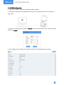
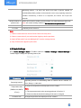
Applicability
This guide is applicable to EM500 series sensors shown as follows, except where otherwise
indicated.
Model
Description
EM500-CO2
Carbon Dioxide Sensor
EM500-LGT
Light Sensor
EM500-PP
Pipe Pressure Sensor
EM500-PT100
PT100 Temperature Sensor
EM500-SMT
Soil Moisture Sensor
EM500-SMTC
Soil Moisture Moisture, Temperature and Conductivity Sensor
EM500-SWL
Submersible Level Sensor
EM500-UDL
Ultrasonic Distance/Level Sensor
Safety Precautions
Milesight will not shoulder responsibility for any loss or damage resulting from not following the
instructions of this operating guide.
The device must not be disassembled or remodeled in any way.
In order to protect the security of the device, please change device password when first
configuration. The default password is 123456.
The device is not intended to be used as a reference sensor, and Milesight will not should
responsibility for any damage which may result from inaccurate readings.
Do not place the device close to objects with naked flames.
Do not place the device where the temperature is below/above the operating range.
Make sure electronic components do not drop out of the enclosure while opening.
When installing the battery, please install it accurately, and do not install the reverse or
wrong model.
The device must never be subjected to shocks or impacts.
Declaration of Conformity
EM500 series is in conformity with the essential requirements and other relevant provisions of
the CE, FCC, and RoHS.
Copyright © 2011-2023 Milesight. All rights reserved.

3
All information in this guide is protected by copyright law. Whereby, no organization or individual
shall copy or reproduce the whole or part of this user guide by any means without written
authorization from Xiamen Milesight IoT Co., Ltd.
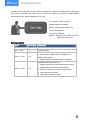
For assistance, please contact
Milesight technical support:
Email: iot.support@milesight.com
Tel: 86-592-5085280
Fax: 86-592-5023065
Address: Building C09, Software Park III,
Xiamen 361024, China
Revision History
Date
Doc Version
Description
Nov. 23, 2020
V 1.0
Initial version
Dec. 7, 2021
V 1.1
Content update
Apr. 11, 2022
V 1.2
1. EM500-SMT/SMTC supports soil type selection
2. Add wirings of EM500-PP-G1/2M-4842 and
EM500-SWL-4846W
3. Support RX2 datarate and frequency settings
May 31, 2023
V 2.0
Update based on hardware v2.x:
1. Add data storage and data transmission feature;
2. Add temperature mutation alarm feature;
3. Add CO2 barometric pressure compensation;
4. Add single-channel mode;
5. Add sensor installation guide.

4
Contents
1. Product Introduction ......................................................................................................................... 5
1.1 Overview ...................................................................................................................................5
1.2 Features ................................................................................................................................... 5
2. Hardware Introduction ...................................................................................................................... 5
2.1 Packing List ..............................................................................................................................5
2.2 Hardware Overview ................................................................................................................. 6
2.3 Dimensions(mm) .....................................................................................................................7
2.4 Power Button ........................................................................................................................... 8
2.5 Pinouts ..................................................................................................................................... 8
3. Device Assembly ............................................................................................................................... 8
4. Operation Guide ...............................................................................................................................10
4.1 Log in the ToolBox .................................................................................................................10
4.1.1 NFC Configuration ...................................................................................................... 10
4.1.2 USB Configuration ...................................................................................................... 11
4.2 LoRaWAN Settings ................................................................................................................ 12
4.3 Basic Settings ........................................................................................................................14
4.4 Advanced Settings................................................................................................................ 15
4.4.1 Data Collection Settings .............................................................................................15
4.4.2 Calibration Settings .................................................................................................... 15
4.4.3 Threshold Settings ..................................................................................................... 16
4.4.4 Data Storage ............................................................................................................... 17
4.4.5 Data Retransmission .................................................................................................. 18
4.5 Maintenance .......................................................................................................................... 20
4.5.1 Upgrade ....................................................................................................................... 20
4.5.2 Backup .........................................................................................................................21
4.5.3 Reset to Factory Default .............................................................................................22
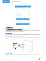
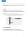
5. Installation ....................................................................................................................................... 23
5.1 EM500 Transceiver Installation ............................................................................................23
5.2 EM500-CO2Sensor Installation ............................................................................................ 24
5.3 EM500-LGT Sensor Installation ............................................................................................24
5.3 EM500-PP Sensor Installation ..............................................................................................25
5.4 EM500-SMT/SMTC Sensor Installation ...............................................................................25
5.4.1 Horizontal Installation ................................................................................................ 26
5.4.2 Vertical Installation .....................................................................................................26
5.5 EM500-SWL Sensor Installation ...........................................................................................27
5.6 EM500-UDL Sensor Installation ............................................................................................28
6. Milesight IoT Cloud Management ..................................................................................................28
7. Device Payload ................................................................................................................................ 29

5
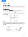
1. Product Introduction
1.1 Overview
EM500 series is a sensor mainly used for outdoor environment through wireless LoRaWAN®
network. EM500 device is battery powered and designed for multiple mounting ways. It is
equipped with NFC (Near Field Communication) and can easily be configured by a smartphone
or a PC software.
Sensor data are transmitted in real-time using standard LoRaWAN®protocol. LoRaWAN®
enables encrypted radio transmissions over long distance while consuming very little power.
The user can obtain sensor data and view the trend of data change through Milesight IoT Cloud
or through the user's own Network Server.
1.2 Features
Up to 15 km communication range
Easy configuration via NFC
Standard LoRaWAN®support
Milesight IoT Cloud compliant
Low power consumption with 19000mAh replaceable battery
2. Hardware Introduction
2.1 Packing List
1 × EM500 Device
(Include Mounting
Bracket)
2 × Wall Mounting
Kits
2 × Fixing Screws
4 × Rubber Screw
Caps
1 ×
Hose Clamp
1 ×
DIN Rail Kit (Optional)
1 ×
Warranty Card
1 ×
Quick Guide
If any of the above items is missing or damaged, please contact your sales representative.

6
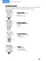
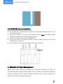
2.2 Hardware Overview
EM500 series sensors is made up of a LoRaWAN®transceiver and a sensor. Among them,
ultrasonic sensors and gas sensors are combined with LoRaWAN®transceiver.
Back View:
④Battery (Internal)
⑤Wall Mounting Holes
⑥Pole Mounting Holes
Front View of EM500-CO2:
①LoRaWAN®Antenna (Internal)
②NFC Area
③Vent Tube
Front View of EM500-UDL:
①LoRaWAN®Antenna (Internal)
②NFC Area
③Ultrasonic Horn
Front View of EM500:
①LoRaWAN®Antenna (Internal)
②NFC Area
③Water-proof Connector

7
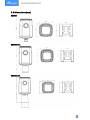
2.3 Dimensions(mm)
EM500
EM500-CO2
EM500-UDL

8
2.4 Power Button
Note: The LED indicator and power button are inside the device. Switch on/off and reset can
also be configured via NFC.
Function
Action
LED Indication
Turn On
Press and hold the button for more than 3 seconds.
Off →On
Turn Off
Press and hold the button for more than 3 seconds.
On →Off
Reset
Press and hold the button for more than 10 seconds.
Blink 3 times.
Check
On/Off Status
Quickly press the power button.
Light On: Device is on.
Light Off: Device is off.
2.5 Pinouts
For parts of EM500 sensors, you need to connect the sensor part to EM500 transceiver
according to the pinouts. You can also find pinouts label on the motherboard.
Note:
1) For EM500-SMT sensor, VOUT=2.5 V; for other sensors, VOUT=12V;
2) For EM500-SMTC sensor, it has a green cable which does not need to connect to EM500
transceiver, please cut off it or insulated wrap it.
3) For EM500-PP-4842 sensor, connect any one of two red cables to motherboard and the other
leaves blank.
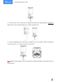
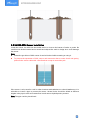
3. Device Assembly
For parts of models, you need to connect sensor to the EM500 transceiver to make the whole
device work.
1. Take off the mounting bracket on the transceiver, remove the screws, rubber seal and cover
on the bottom of the device.
PIN
LGT
PP-4780/S
WL
PP-4842/SW
L-4846W
PT100
SMT
SMTC
1
Black/GN
D
Red/GND
White/GND
White/GN
D
Black/G
ND
Black/GN
D
2
---
---
Red/AIN
---
Yellow/A
IN
---
3
---
---
---
---
---
---
4
Blue/B
White/B
---
Red/PT1
---
White/B
5
Green/A
Yellow/A
---
Red/PT2
---
Yellow/A
6
Red/VOU
T
Black/VOU
T
Black/VOUT
---
Brown/V
OUT
Red/VOU
T

9
2. Lock the sensor wires to the block according to the label on the motherboard or chapter 2.5,
then pass the sensor cable through the cap, rubber seal and cover.
3. Put the motherboard back and restore everything to its due position. When restoring the
cover, ensure the arrow faces the front of the transceiver.
Note: Rubber seal and rubber screw caps should be installed accordingly, or the water will come
into the device.

10
4. Operation Guide
4.1 Log in the ToolBox
EM500 series can be monitored and configured via ToolBox App or ToolBox software. Before
configuration, ensure the insulating sheet inside the device has be pulled out and battery is not
placed reversed.
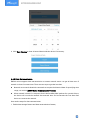
4.1.1 NFC Configuration
1. Download and install Milesight ToolBox App from Google Play or Apple App Store.
2. Enable NFC on the smartphone and launch Milesight ToolBox.
3. Attach the smartphone with NFC area, click NFC Read button to read device information. You
can read and configure the device by tapping the Read/Write device on the App. In order to
protect the security of the device, please change password when first configuration. The default
password is 123456.
Note:
4) Ensure the location of smartphone NFC area and it’s recommended to take off phone case.
5) If the smartphone fails to read/write configurations via NFC, keep the phone away and back
to try again.
6) EM500 series can also be configured by dedicated NFC reader, which can be purchased from
Milesight IoT.

11
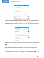
4.1.2 USB Configuration
1. Download ToolBox software from Milesight official website.
2. Release the enclosure of the EM500 transceiver, then connect the device to a computer via
Type-C port.
3. Open the ToolBox and select type as General, then click password to log in ToolBox. (Default
password: 123456)
4. After logging in the ToolBox, you can turn on/off devices and change other settings.

12
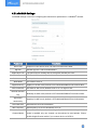
4.2 LoRaWAN Settings
LoRaWAN settings is used for configuring the transmission parameters in LoRaWAN®network.
Parameters
Description
Device EUI
Unique ID of the device which can also be found on the label.
App EUI
Default App EUI is 24E124C0002A0001.
Application Port
The port used for sending and receiving data, default port is 85.
Join Type
OTAA and ABP mode are available.
LoRaWAN Version
V1.0.2, V1.0.3 are available.
Work Mode
It’s fixed as Class A.
Application Key
Appkey for OTAA mode, default is 5572404C696E6B4C6F52613230313823.
Device Address
DevAddr for ABP mode, default is the 5th to 12th digits of SN.
Network Session
Key
Nwkskey for ABP mode, default is 5572404C696E6B4C6F52613230313823.
Application
Session Key
Appskey for ABP mode, default is 5572404C696E6B4C6F52613230313823.
RX2 Data Rate
RX2 data rate to receive downlinks.
RX2 Frequency
RX2 frequency to receive downlinks. Unit: Hz
Channel Mode
Select Standard-Channel mode or Single-Channel mode. When Single-Channel
mode is enabled, only one channel can be selected to send uplinks. Please
enable Single-Channel mode if you connect device to DS7610.

13
Channel
Enable or disable the frequency to send uplinks.
If frequency is one of CN470/AU915/US915, enter the index of the channel
that you want to enable and make them separated by commas.
Examples:
1, 40: Enabling Channel 1and Channel 40
1-40: Enabling Channel 1 to Channel 40
1-40, 60: Enabling Channel 1 to Channel 40 and Channel 60
All: Enabling all channels
Null: Indicates that all channels are disabled
Spread Factor
If ADR is disabled, the device will send data via this spread factor.
Confirmed Mode
If the device does not receive ACK packet from network server, it will resend
data once.
Rejoin Mode
Reporting interval ≤ 35 mins: the device will send a specific number of
LinkCheckReq MAC packets to the network server every reporting interval or
2*reporting interval to validate connectivity; If there is no response, the device
will re-join the network.

14
Reporting interval > 35 mins: the device will send a specific number of
LinkCheckReq MAC packets to the network server every reporting interval to
validate connectivity; If there is no response, the device will re-join the
network.
Set the number of
packets sent
When rejoin mode is enabled, set the number of LinkCheckReq packets sent.
Note: the actual sending number is Set the number of packets sent + 1.
ADR Mode
Allow network server to adjust datarate of the device.
Tx Power
Transmit power of device.
Note:
1) Please contact sales for device EUI list if there are many units.
2) Please contact sales if you need random App keys before purchase.
3) Select OTAA mode if you use Milesight IoT cloud to manage devices.
4) Only OTAA mode supports rejoin mode.
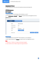
4.3 Basic Settings
Go to Device Settings > Basic of ToolBox software or Device > Settings > General Settings of
ToolBox App to change the reporting interval, etc.
Parameters
Description
Reporting Interval
Reporting interval of transmitting data to network server. Default: 10
mins, Range: 1-1080 mins.
Temperature Unit
(EM500-CO2/SMTC/
PT100)
Change the temperature unit displayed on the ToolBox.
Note:
1) The temperature unit in the reporting package is fixed as °C.
2) Please modify the threshold settings if the unit is changed.
Pressure Unit
Change the pressure unit displayed on the ToolBox.

15
(EM500-PP)
Note:
1) The pressure unit in the reporting package is fixed as kPa.
2) Please modify the threshold settings if the unit is changed.
Soil Type
(EM500-SMT/SMTC)
Change the suitable soil type. It only works with hardware V2.0 and
above.
SMT: Mineral soil, potting soil and rockwool are optional.
SMTC: Mineral soil, sandy soil, clay and organic soil are optional.
Data Storage
Disable or enable data storage locally. (see section 4.4.4 to export data )
Data Retransmission
Disable or enable data retransmission. (see section 4.4.5)
Change Password
Change the password for ToolBox App or software to read/write this
device.
4.4 Advanced Settings
4.4.1 Data Collection Settings
Enable or disable to collect and upload corresponding data. This feature is only supported by
EM500-CO2and EM500-SMTC sensors.
4.4.2 Calibration Settings
Numerical Calibration:
ToolBox supports numerical calibration for all items. Go to Device Settings > Basic of ToolBox
software or Device > Settings > Calibration Settings of ToolBox App to type the calibration value
and save, the device will add the calibration value to raw value.

16
CO2Calibration:
For EM500-CO2, ToolBox provides more calibration methods:
Barometric Pressure Calibration: this only works when barometric sensor is enabled.
Manual Calibration: Put the device in an open outdoor environment for more than 10 minutes
and click this button to calibrate the CO2value.
Factory Calibration Restored: Clean the manual calibration and turn back to factory calibration.
Abnormal Value Prevention:
For EM500-PT100/SWL/UDL, ToolBox provides abnormal value prevention feature for accurate
results. If the current value exceeds the range of previous value, the sensor will discard the
current value and remeasure again. Take 20% as example, if last value is 5 and max range is 10,
the next value should within the range 3-7, or the sensor will measure again.
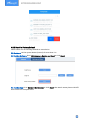
4.4.3 Threshold Settings
Enable the threshold settings and input the threshold. EM500 series will upload the current data
once instantly when the collected value exceeds the preset threshold. Only when the value turns

17
back to normal and triggers the threshold again, it will send a new alarm.
EM500-PT100/CO2/SMTC supports to send alarms when mutation of temperature value
reaches the threshold value.
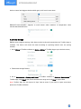
4.4.4 Data Storage
EM500 series supports storing 1000 data records locally and exports data via ToolBox App or
software. The device will record the data according to reporting interval even not joining
network.
1. Go to Status of ToolBox software or Device > Status of ToolBox App to sync the device time;
2. Enable data storage feature.
3. Go to Maintenance > Backup and Reset of ToolBox software or Device > Maintenance of
ToolBox App, click Export, then select the data time range and click Save to export data.
Note: ToolBox App can only export 14 days’ data at most. If you need to export more data,
please use ToolBox software.

18
4. Click Data Cleaning to clear all stored data inside the device if necessary.
4.4.5 Data Retransmission
EM500 series supports data retransmission to ensure network server can get all data even if
network is down for some times. There are two ways to get the lost data:
Network server sends downlink commands to enquire the historical data for specifying time
range, see section
EM500 Series Communication Protocol;
;
When network is down if no response from LinkCheckReq MAC packets for a period of time,
the device will record the network disconnected time and re-transmit the lost data after
device re-connects the network.
Here are the steps for data retransmission:
1. Enable data storage feature and data retransmission feature;

19
2. Enable rejoin mode feature and set the number of packets sent. Take below as example, the
device will send LinkCheckReq MAC packets to the network server regularly to check if the
network is disconnected; if there is no response for 8+1 times, the join status will change to
de-active and the device will record a data lost time point(the time to join the network).
3. After the network connected back, the device will send the lost data from the point in time
when the data was lost according to the reporting interval.
Note:
1) If the device is rebooted or re-powered when data retransmission is not completed, the
device will re-send all retransmission data again after device is reconnected to the network;
2) If the network is disconnected again during data retransmission, it will only send the latest
disconnection data;
3) The retransmission data format is started with “20ce”, please refer to
EM500 Series

20
Communication Protocol
.
4) Data retransmission will increase the uplinks and shorten the battery life.
4.5 Maintenance
4.5.1 Upgrade
ToolBox Software:
1. Download firmware from Milesight official website to your PC.
2. Go to Maintenance > Upgrade, click Browse to import firmware and upgrade the device.
ToolBox App:
1. Download firmware from Milesight official website to your smartphone.
2. Open ToolBox App and click Browse to import firmware and upgrade the device.
Note:
1) Operation on ToolBox is not supported during the upgrade.
2) Only Android version ToolBox supports the upgrade feature.
Page is loading ...
Page is loading ...
Page is loading ...
Page is loading ...
Page is loading ...
Page is loading ...
Page is loading ...
Page is loading ...
Page is loading ...
-
 1
1
-
 2
2
-
 3
3
-
 4
4
-
 5
5
-
 6
6
-
 7
7
-
 8
8
-
 9
9
-
 10
10
-
 11
11
-
 12
12
-
 13
13
-
 14
14
-
 15
15
-
 16
16
-
 17
17
-
 18
18
-
 19
19
-
 20
20
-
 21
21
-
 22
22
-
 23
23
-
 24
24
-
 25
25
-
 26
26
-
 27
27
-
 28
28
-
 29
29


Milesight EM500-PT100 User guide
- Type
- User guide
Ask a question and I''ll find the answer in the document
Finding information in a document is now easier with AI
Related papers
-
Milesight EM500 Series Outdoor Environment Monitoring Sensor Featuring LoRaWAN User guide
-
Milesight EM500-CO User guide
-
-
-
-
Milesight WS52x User guide
-
Milesight AM103L User guide
-
-
Milesight WS202 User guide
-
Other documents
-
DirekTronik 20113574 User guide
-
Tekelek TEK888 Installation guide
-
-
 LINOVISION IOT-S500AM Series User guide
-
 Ursalink EM500-PP User manual
-
 Ursalink UC11-T1 Quick Manual
-
 RG2i WS136 User guide
-
 eLICHENS LoRaWAN CO2 User manual
-
 Nordic Propeye OY1211 User manual
-
 Telethings LoNFC-1 User manual


