Skipper GDS102 Operation and Installation Manual
- Type
- Operation and Installation Manual

Document no: DM-G002-SB
Edition: 2012-05-10
Rev 1.12.6
SKIPPER Electronics AS Telephone: +47 23 30 22 70
Enebakkveien 150 Telefax: +47 23 30 22 71
P. O. Box 151, Manglerud E-mail: support@skipper.no
0612 Oslo, Norway Co. reg. no: NO-965378847-MVA
www.skipper.no
GDS102
Operation and Installation Manual
Dual Channel Graphic Depth Sounder (10 - 265 kHz)

Page 2 of 74
SKIPPER Electronics AS
Version: 2012-05-10 Sw 1.12.6
GDS102 Operation and Installation Manual
Weitergabe sowie vervielfältigung dieser unterlage, verwertung
und mitteilung ihres inhaltes nicht gestattet, soweit nicht
ausdrücklich zugestanden. Zuwiderhandlungen verpichten zu
schadenersatz.
Toute communication ou reproduction de ce document,
toute exploitation ou communication de ou son contenu sont
interdites, sauf autorisation expresse. Tout manquement à
cette règle est illicite et expose son auteur au versement de
dommeges et intèrèts.
Copying of this document, and giving it to others and the use
or communication of contents thereof, are forbidden without
express authority. Offenders are liable to the payment of
damages.
Sin nuestra expresa autorización, queda terminantemente
prohibida la reproducción total o parcial de este documento,
asì como su uso Indebido y/o su exhibición o comunicación
a terceros. De los infractores Se exigirá el correspondiente
resarcimiento de daños y perjuicios.
IMPORTANT
When doing service or repair, please wait two minutes after power off, before unplugging
internal connectors.

Page 3 of 74
SKIPPER Electronics AS
Version: 2012-05-10 Sw 1.12.6
GDS102 Operation and Installation Manual
Contents
1. INTRODUCTION..........................................................................................................................6
System Summary ............................................................................................................................................... 6
Transducers ........................................................................................................................................................ 6
Primary/Secondary Channels Concept .............................................................................................................. 6
Operator Panel and Data Entry .......................................................................................................................... 6
Recorded Data Storage ...................................................................................................................................... 7
Fig. 1.1 Operator Unit Panel Layout .................................................................................................................. 7
Fig. 1.2. System Diagram .................................................................................................................................. 8
Interfacing .......................................................................................................................................................... 9
Outputs ..........................................................................................................................................................................9
Inputs .............................................................................................................................................................................9
Alarms ................................................................................................................................................................ 9
Additional Features ............................................................................................................................................ 9
Auto Range....................................................................................................................................................................9
External Printer .............................................................................................................................................................9
Options ..........................................................................................................................................................................9
Remote Sounding Control ...........................................................................................................................................10
Sound Speed Calibration .............................................................................................................................................10
2 OPERATION .................................................................................................................................11
Parameter entry ................................................................................................................................................ 11
Fig. 2.1. Setting and Parameter Entry Flowchart ........................................................................................................11
Operation Screens ............................................................................................................................................ 12
Primary Operation Screens (screen 1 - 3) ........................................................................................................ 13
Fig. 2.2. Screen 1. Gain, TVG and alarm settings. .....................................................................................................13
Fig. 2.3. Screen 2. Display and print settings..............................................................................................................14
Fig. 2.4. Screen 3. Power adjustment and options. .....................................................................................................15
Secondary Operation Screens (screen 4 - 12) .................................................................................................. 16
Fig. 2.5. Screen 4. Transducer details. ........................................................................................................................16
Fig. 2.6. Screen 5. Calendar and clock setting. ..........................................................................................................17
Fig. 2.7. Screen 6. Units of measurement. ..................................................................................................................18
Fig. 2.8. Screen 7. Interface setup screen. ...................................................................................................................19
Fig. 2.9. Screen 8. Recordings selection and play back. .............................................................................................20
Fig. 2.10. Screen 9. Recordings options......................................................................................................................21
Fig. 2.11. Screen 10. NMEA control screen. ..............................................................................................................22
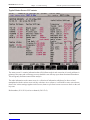
Fig. 2.12. Screen 11. System status screen. .................................................................................................................23
Fig. 2.13. Screen 12. Oscilloscope screen. ..................................................................................................................24
Principal Functions. ......................................................................................................................................... 26
Depth Range ................................................................................................................................................................26
Picture Speed ...............................................................................................................................................................26
Brightness (backlight) adjustment...............................................................................................................................27
Day/Night ....................................................................................................................................................................27
Gain and TVG (Time Variable Gain) ..........................................................................................................................27
Digital indication .........................................................................................................................................................27
Frequency ....................................................................................................................................................................27
Output Power ..............................................................................................................................................................27
Draught and Offset ......................................................................................................................................................27
External Printer Operation ..........................................................................................................................................28
Alarm settings and acknowledgment ..........................................................................................................................28
Clock and Calendar Settings .......................................................................................................................................28
Data Logging (Recordings Memory) ..........................................................................................................................28
System ON/OFF ..........................................................................................................................................................29
Simulator .....................................................................................................................................................................29

Page 4 of 74
SKIPPER Electronics AS
Version: 2012-05-10 Sw 1.12.6
GDS102 Operation and Installation Manual
Status Screen ...............................................................................................................................................................29
Oscilloscope Screen ....................................................................................................................................................29
Nonvolatile Parameter Memory. .................................................................................................................................29
Data type .....................................................................................................................................................................29
Basic Algorithm Considerations ...................................................................................................................... 30
Bottom detection .........................................................................................................................................................30
Ping to Ping ltering ...................................................................................................................................................30
3. INSTALLATION .........................................................................................................................31
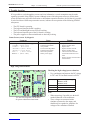
Standard System Supply .................................................................................................................................. 31
Transducer Installation ..................................................................................................................................... 31
Location.......................................................................................................................................................................31
Installation Details ......................................................................................................................................................31
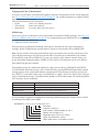
Fig. 3.1. Basic System Conguration..........................................................................................................................32
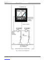
Transducer Junction Box ................................................................................................................................. 33
Fig. 3.2. Transducer junction box................................................................................................................................33
Operator Unit Installation ................................................................................................................................ 34
115/230 V selection on Combo Terminal board inside Display Unit..........................................................................34
Fig 3.3. Operator unit. .................................................................................................................................................35
Fig. 3.4. AC Voltage selection and fuses. ....................................................................................................................36
Voltage selection connectors and fuses, Terminal Board ............................................................................................36
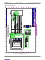
External Interface Ports ...............................................................................................................................................37
Fig. 3.5. Data Communication Interfaces. ..................................................................................................................37
Fig. 3.6. Data Communication Interfaces. ..................................................................................................................38
Back-up battery jumper JP 200 ...................................................................................................................................39
Fig. 3.7. Back-up battery jumper JP200, on I/O board. ..............................................................................................39
Interfacing ........................................................................................................................................................ 40
NMEA interface ..........................................................................................................................................................40
Alarm relay..................................................................................................................................................................40
Analogue interfaces .....................................................................................................................................................40
Transmitter trigger pulse and bottom pulse outputs ....................................................................................................41
External alarm reset input ...........................................................................................................................................41
External printer connection .........................................................................................................................................41
Repeaters/Slaves .........................................................................................................................................................41
Remote Keyboard........................................................................................................................................................42
Remote Sounding Control ...........................................................................................................................................42
Optocoupler 2 output...................................................................................................................................................42
EMC ................................................................................................................................................................. 42
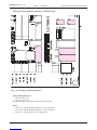
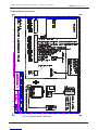
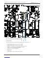
Terminal board connections ............................................................................................................................. 43
Fig. 3.8. Terminal board connections ..........................................................................................................................43
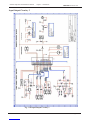
Input/Output Circuitry 1 .................................................................................................................................. 44
Fig. 3.9. Input/Output Circuitry 1 ...............................................................................................................................44
Input/Output Circuitry 2 .................................................................................................................................. 45
Fig. 3.10. Input/Output Circuitry 2 .............................................................................................................................45
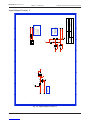
Input/Output Circuitry 3 .................................................................................................................................. 46
Fig. 3.11. Input/Output Circuitry 3 .............................................................................................................................46
4. START-UP AND SYSTEM ADAPTION ....................................................................................47
System Adaptation ........................................................................................................................................... 47
Primary channel assignment .......................................................................................................................................47
Transducer installation position ..................................................................................................................................47
Screen presentation .....................................................................................................................................................47
Alarm limits and local alarm buzzer control ...............................................................................................................47
Analogue Outputs Range Selection ............................................................................................................................47
Clock and calendar settings .........................................................................................................................................47
Language and Units of Measurement .........................................................................................................................48
NMEA Setup ...............................................................................................................................................................48

Page 5 of 74
SKIPPER Electronics AS
Version: 2012-05-10 Sw 1.12.6
GDS102 Operation and Installation Manual
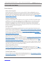
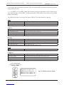
Fig. 4.1. NMEA connector XJ402. ..............................................................................................................................49
Filter setup ...................................................................................................................................................................50
Fig. 4.3. SW1 bandwidth settings ...............................................................................................................................50
Fig. 4.2. Frequency settings ........................................................................................................................................50
Frequency setup ..........................................................................................................................................................50
Options ............................................................................................................................................................. 57
Calibration, sound speed .............................................................................................................................................57
Remote sounding control ............................................................................................................................................57
Ping .............................................................................................................................................................................57
5. TROUBLE SHOOTING .............................................................................................................58
High voltage measurement. .........................................................................................................................................58
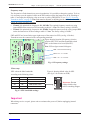
Fig. 5.1. Function LEDs, on terminal board. ..............................................................................................................59
Function LEDs. ...........................................................................................................................................................59
Typical Status Screen 11 Contents ................................................................................................................... 60
6. USER MAINTENANCE .............................................................................................................63
Transducer maintenance .................................................................................................................................. 63
Operator Unit Maintenance .............................................................................................................................. 63
7. SYSTEM SPECIFICATIONS ...................................................................................................64
Functional Properties ....................................................................................................................................... 64
Performance ..................................................................................................................................................... 64
Transducer and Junction Box ......................................................................................................................................65
Operator Unit Cabinet .................................................................................................................................................65
Dimensions ...................................................................................................................................................... 66
8. SERVICE ......................................................................................................................................67
CPU 6742VE Setup ....................................................................................................................................................68
Master Reset Procedure...............................................................................................................................................69
Upgrading Software ....................................................................................................................................................69
9. EMC MOUNTING KIT ..............................................................................................................70
10. NOTES ........................................................................................................................................71
11. INDEX .........................................................................................................................................72

Page 6 of 74
SKIPPER Electronics AS
Version: 2012-05-10 Sw 1.12.6
GDS102 Operation and Installation Manual
Chapter: 1. Introduction
1. Introduction
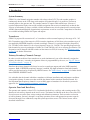
System Summary
GDS102 is a dual channel navigation sounder with a large colour LCD. The echo sounder graphics is
continuously shown on the LCD along with complete navigational details. It is possible to connect an
external printer to the operator unit. The sounder contains a Compact Flash which keeps 24 hours of
recorded information. Depth, time and all available navigation data are stored continuously so that the last
24 hours of information is always available. All this information may also be printed on the external printer.
All IMO (International Maritime Organization) requirements are met or exceeded. Comprehensive interfaces
are available including NMEA 0183 inputs and outputs.
Transducers
GDS102 is prepared for connection of 1 or 2 transducers with a resonant frequency in the range of 10 - 265
kHz. Transmitter stage of the transceiver PCB is tuned to impedance of 100 Ohm, so the transducer type (if
not supplied by SKIPPER) should be selected accordingly. Channel 1 is optimized for higher frequencies
(50 - 265 kHz), while channel 2 is for a lower frequency range (10 - 50 kHz). The operating frequencies for
both channels are preset in production to 50 kHz (ch 1) and 200 kHz (ch 2) or to customer specication. The
frequencies can be changed with DIP switches on the transceiver PCB, if necessary. See”Frequency setup”
on page 50 for further instructions.
Primary/Secondary Channels Concept
In order to avoid confusion if two transducers are used simultaneously, one of the channels is assigned as
primary, the other one - secondary. Assignment of these is programmable by the user, see “Fig. 2.5. Screen
4. Transducer details.” on page 16.
Data from the primary channel will always be used to set analogue outputs and in the NMEA standard
sentences. Note: If SKIPPER proprietary message is enabled, the depth information from both channels
will be provided and can be recognized by NMEA listeners. See”NMEA Setup” on page 48 for further details
about SKIPPER PSKPDPT format.
It is advisable, that the channel which has a transducer with better installation and performance conditions
is assigned as primary. In most cases that would be the channel with a transducer installed forward. It is
also important that the primary channel is set to an IMO approved transducer for the whole system to be
approved. See “Primary channel assignment” on page 47.
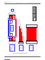
Operator Panel and Data Entry
The operator unit contains a colour LCD, a keyboard with xed keys, soft keys and a rotating encoder. The
function of each soft key depends on the active screen. The buttons are labeled on the lower rim of the LCD.
Several screens are used to enter various settings and calibration parameters. Each screen has a selection
of soft key buttons. Screens 1 through 3 are primary operation screens with appropriate operator controls.
Screens 4 through 12 are calibration, setup and system supervision screens. The various screens will be
described in detail later.

Page 7 of 74
SKIPPER Electronics AS
Version: 2012-05-10 Sw 1.12.6
GDS102 Operation and Installation Manual Chapter: 1. Introduction
The LCD is backlit, and backlight intensity may be adjusted by the user. Day or night vision modes can be
selected according to the ambient light conditions. The echogram is normally displayed continuously on the
LCD. An optional external printer can be connected, if hardcopy documentation is required. The operator
unit is normally ush mounted.
Recorded Data Storage
Depth and other navigational data are continuously stored for 24 hours in non-volatile memory (Compact
Flash). See “Data Logging (Recordings Memory)” on page 28. A HP Deskjet printer or Epson D88
printer with Centronics (parallel) interface may be connected for a paper copy, (ask SKIPPER for printer
specication). Alternatively an Epson LQ-300+ printer for continuous paper feed may be used. Printer is
only required when hard copy documentation is necessary.
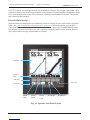
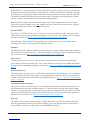
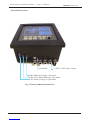
Fig. 1.1 Operator Unit Panel Layout
Graphics
Soft key
texts
Soft keys
Depth
range
Picture
speed
Screen
select
Day/Night Brightness
Encoder
Fixed keys

Page 8 of 74
SKIPPER Electronics AS
Version: 2012-05-10 Sw 1.12.6
GDS102 Operation and Installation Manual
Chapter: 1. Introduction
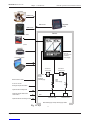
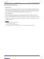
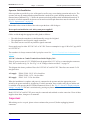
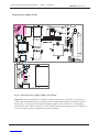
Fig. 1.2. System Diagram
Navigator
Speed Log
Computer system
Cabinet
Analogue depth information
Transducer
Junction Box
0-10V / 4-20 mA
115/230 V AC
24 V DC
2 x 2.5 sq. mm
screened.
(Yard Supply)
NMEA 0183
NMEA 0183
NMEA 0183
Hull
External alarm reset
Standard Supply except Yard Supply cables
1 pair each
xducer,
2.5 mm
screened.
(Yard Supply)
Optional external keyboard
Optional remote VGA and/or
LCD monitor
Optional external sounding control
Transducer Tank
NMEA 0183 Repeater
IR301
External printer
Transducer
Junction Box
Transducer Tank
Steel
Pipe
(Yard Supply)
Logging to Compact Flash

Page 9 of 74
SKIPPER Electronics AS
Version: 2012-05-10 Sw 1.12.6
GDS102 Operation and Installation Manual Chapter: 1. Introduction
Interfacing
The GDS102 has various interface possibilities.
Outputs
• Transmitter trigger pulse and bottom pulse outputs. See “Transmitter trigger pulse and bottom pulse
outputs” on page 41.
• Analogue outputs 0 - 10 V and 4 - 20 mA. See “Analogue interfaces” on page 40.
• NMEA 0183 interface outputs of depth information. See “NMEA interface” on page 40 and “NMEA
Setup” on page 48.
• External alarm relay output. See “Alarm relay” on page 40.
• System malfunction optocoupler output.
• External printer and monitor. See “External Interface Ports” on page 37.
Inputs
• NMEA 0183 interface input of position, heading, speed and UTC (Coordinated Universal Time). See
“NMEA Setup” on page 48.
• External alarm reset. See “External alarm reset input” on page 41 and “Input/Output Circuitry 3” on
page 46.
• External control and synchronization of transmitter (optional). See “Remote Sounding Control” on
page 57.
Alarms
Shallow and deep water alarms may be adjusted on screen 1. See “Fig. 2.2. Screen 1. Gain, TVG and alarm
settings.” on page 13. A relay output is provided in GDS102 for interface to external alarm systems. At local
alarm conditions, an audible alarm is also provided.
Additional Features
In addition to the features demanded by the IMO regulations, the following features are available:
Repeaters/Slaves
Graphic CRT or LCD display or digital depth slave repeaters may be connected to the system.
Auto Range
This feature will automatically adjust the depth range to maintain the bottom contour within the middle
half of the screen height, and is accessible on screen 3. See “Fig. 2.4. Screen 3. Power adjustment and
options.” on page 15.
External Printer
Printer for endless paper or inkjet printer for single sheets (ask SKIPPER for available types) may be
connected for hardcopy requirements.
Options
• Remote keyboard.
• Permanent reduction of output power for adaption to various transducers.

Page 10 of 74
SKIPPER Electronics AS
Version: 2012-05-10 Sw 1.12.6
GDS102 Operation and Installation Manual
Chapter: 1. Introduction
Non-standard features, available as options, which are not approved for normal use for navigation by IMO
(contact SKIPPER for more information) include:
Remote Sounding Control
This option lets the GDS102 being controlled remotely in continuous/edge/level/single (manual) ping
modes. It can be useful in case of multiple hydroacoustic installations to avoid interference between
different systems. If installed, this option is accessible on screen 3. See “Fig. 2.4. Screen 3. Power
adjustment and options.” on page 15.
Sound Speed Calibration
This option will enable adjustment of the sound speed value used for the depth calculations. The
standard value is 1500 m/s, but the user may set values from 1400 to 1550 m/s to accommodate accurate
propagation speed in known water conditions. If installed, this option is accessible on screen 3. See “Fig.
2.4. Screen 3. Power adjustment and options.” on page 15.

Page 11 of 74
SKIPPER Electronics AS
Version: 2012-05-10 Sw 1.12.6
GDS102 Operation and Installation Manual Chapter: 2 Operation
2 Operation
When the installation is complete, and power is connected to the operator unit, the system is switched on-off
by a power switch inside the cabinet.
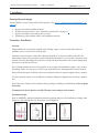
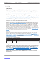
Parameter entry
The xed function buttons, the soft key buttons and the rotating encoder allow the user to adjust the
parameters, setpoints and other data. The following owchart illustrates the procedure for changing settings
and entering data. The various screens are shown in detail later.
Example of parameter entry
Suppose you want to enter a value of 800 m for the depth range. The present setting is 100 m. Press the
DEPTH RANGE button and keep it pressed while you turn the encoder clockwise. Observe the depth range
increase to 800 m, let go of the encoder and release the DEPTH RANGE button. You could also have started
from the standard value 1000 m and decreased to 800 m by turning the encoder counter-clockwise.
Buttons with less than 6 possible states or values can be operated without using the encoder at all. The setup
will be remembered when the unit is turned off.
10
20001123sw503
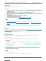
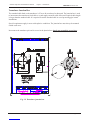
2. Operation
When the installation is complete, and power is connected to the Operator Unit, the system is
switched on by pressing any button. The unit is switched off by pressing the "SYSTEM off" soft
key button on Screen 2.
Parameter entry
The fixed function buttons and the soft key buttons of the various screens along with the rotating
encoder, facilitates entry of parameters, setpoints and other data. The following flow chart
illustrates the procedure for changing settings and entering data. The various screens are shown in
detail in the Operation Section.
Any
Screen
Rotate encoder
in either
direction to
obtain desired
state or setting
Check for
desired result
Any valid fixed or
soft key
Advances to next
fixed state or
value
PRESS
BUTTON
ONCE
KEEP
BUTTON
PRESSED
RELEASE
BUTTON
Fig. 2.1 Setting and Parameter Entry Flowchart
Fig. 2.1. Setting and Parameter Entry Flowchart

Page 12 of 74
SKIPPER Electronics AS
Version: 2012-05-10 Sw 1.12.6
GDS102 Operation and Installation Manual
Chapter: 2 Operation
Operation Screens
Each of the operation screens contains a graphic picture and a selection of up to 6 soft key buttons. The
various screens are selected by keeping the SCREENS button pressed and rotating the encoder in either
direction. Turning the encoder clockwise cycle the screens in the sequence 1 to 12, and counter clockwise
rotation cycles the screens in the sequence 12 to 1. Screens 1, 2 and 3, covering the primary functions, may
also be cycled by repeatedly pressing the SCREENS button.
The screen layouts are outlined in g. 2.2 through 2.13. The various soft key functions are described with
each screen.
Note: Some of the soft keys on the following pages appear “dimmed”. The reason for this, is that the screen
shots are taken in “demo” mode.
Note: The primary and secondary channels frequencies are indicated at the top of the screens along with
draught settings regardless of the selected screen and graphic screen layout. PRIMARY channel information
is marked by blue colour. (See below).
Primary channel
indication
Draught
indication
Time indication
manual or from
GPS
Draught
indication
Position
from GPS
Speeed
indication
from GPS
Heading
indication
from GPS

Page 13 of 74
SKIPPER Electronics AS
Version: 2012-05-10 Sw 1.12.6
GDS102 Operation and Installation Manual Chapter: 2 Operation
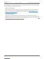
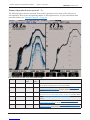
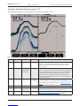
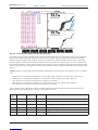
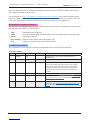
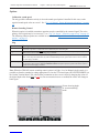
Fig. 2.2. Screen 1. Gain, TVG and alarm settings.
Soft key Name Range/
value
Default
value
Description
1 SELECT CHN Ch1 / Ch2 Ch 2 Selected channel enables adjustment of GAIN and TVG. The frequency
of the channel is displayed next to the channel number.
2 GAIN 0 - 100 % 49 % Gain adjustment. (% represents range 1 - 50 dB). See “Gain and TVG
(Time Variable Gain)” on page 27 for further details about the gain
function.
3 TVG 0 - 100 % 50 % Time Variable Gain adjustment. (% represents 10 - 50 dB suppression).
See “Gain and TVG (Time Variable Gain)” on page 27 for further details.
4 MARK Line Mark line will be provided both on the screen and paper. (If printer is
active).
5 ALARM ▲ 0 - 99 m 0 m Shallow water alarm adjustment. See “Alarm limits and local alarm
buzzer control” on page 47 for further details about alarm function.
6 ALARM ▼ 0 - 5000 m 100 m Deep water alarm adjustment. See “Alarm limits and local alarm buzzer
control” on page 47 further details about alarm function.
Primary Operation Screens (screen 1 - 3)
The following gures show the operation of the primary operation screens. Some of the soft keys are
self explanatory. Refer to the corresponding chapter in “Principal Functions” for more information about
particular features. See “Principal Functions.” on page 26.

Page 14 of 74
SKIPPER Electronics AS
Version: 2012-05-10 Sw 1.12.6
GDS102 Operation and Installation Manual
Chapter: 2 Operation
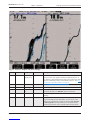
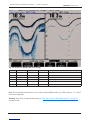
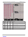
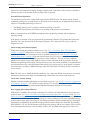
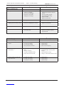
Fig. 2.3. Screen 2. Display and print settings.
Soft key Name Range/value Default value Description
1 DISPLAY v.split / h.split
/primary freq
v.split Selection of screen layout (either vertical or horizontal split of the
total screen area, only primary transducer). Note: If only one of
the channels is being displayed, the other one can still be activated,
unless it is disabled by soft key LOCATION at screen 4. See “Fig.
2.5. Screen 4. Transducer details.” on page 16.
2 Not used.
3 DIGIT Small/large Small Selection of digital depth indication size.
4 PRINT Off [not ready]
/on
Off Start and stop of continuous printing. Note: If printer is not
connected, this button is “Dimmed” and can not be used.
5 SCREEN Print Screen hardcopy, can be used for documentation and trouble-
shooting.
6 SYSTEM On/off On Setting the sounder in standby mode, switching off the major
power consuming elements (transmitter, LCD screen etc.) The
sounder can be restarted by pressing any button. Note: The unit
is still energized!!! Do not perform any re-connections before
switching off the mains on the terminal PCB inside the cabinet.

Page 15 of 74
SKIPPER Electronics AS
Version: 2012-05-10 Sw 1.12.6
GDS102 Operation and Installation Manual Chapter: 2 Operation
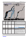
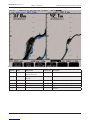
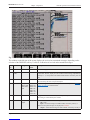
Fig. 2.4. Screen 3. Power adjustment and options.
Soft key Name Range/value Default value Description
1 SELECT
CHN
Ch1/Ch2 Ch 2 Selected channel enables adjustment of POWER, and
DRAUGHT. The channel frequency is displayed next to the
channel number.
2 POWER 1 - 100 % 50 % Transmitter power adjustment.
3 DRAUGHT 0.00 to 99.9 m 0.00 m Draught correction, distance between the lowest point of the
vessel (near the transducer) and the water surface. Setting to
zero will display the depth from the lowest point. Note: Set
individually for both channels.
Also see OFFSET on “Fig. 2.13. Screen 12. Oscilloscope
screen.” on page 24.
4 (optional) SOUND 1400 - 1550 m/s 1500 m/s Sound speed setting.
5 RANGE Manual/autorange Manual Automatic range control.
6 (optional) PING Continuous/edge/
level/manual
External sounding control.
Continuous - internal control of the soundings.
Edge - external control of the soundings, synchronized with
an edge (positive or negative) of the external signal.
Level - external control of the soundings, enabling/disabling
continuous soundings by the level of the external signal.
Manual (Single) - control of the soundings by pressing
PICTURE SPEED key.

Page 16 of 74
SKIPPER Electronics AS
Version: 2012-05-10 Sw 1.12.6
GDS102 Operation and Installation Manual
Chapter: 2 Operation
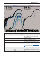
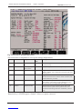
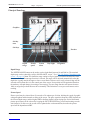
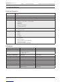
Fig. 2.5. Screen 4. Transducer details.
Soft key Name Range/value Default value Description
1 SELECT CHN Ch1/Ch2 Ch 2 Selected channel enables adjustment of LOCATION,
FREQUENCY, SCREEN POS, PRIMARY settings, explained
below. The frequency of the channel is displayed next to the
channel number.
2 LOCATION FWD/AFT/
PORT/STRB/
not inst./pos?
Pos? Transducer position. Information is being indicated on the
screen for easy reference to the transducer and used in SKIPPER
proprietary NMEA sentence. Note: If “not inst” (not installed)
is selected, the corresponding channel is not operative and will
never be displayed (single channel mode). One channel must
always be operative, therefore “not inst” can be selected only for
one channel at a time.
3 FREQUENCY 10 - 265 kHz Ch 1: 200 kHz
Ch 2: 50 kHz
Adjustment of the frequency of currently selected channel. Note:
The actual frequency of the channels must be programmed by the
DIP switches on the transceiver PCB. See “Frequency setup” on
page 50 for further instructions.
4 Not used
5 SCREEN POS (Left/right)/
(upper/lower)
Left Selects the screen position of graphical window of currently
selected channel. (Dependant of v.split/h.split screen 2).
6 PRIMARY Yes/no Ch 2 Toggles PRIMARY property of the selected channel. See
“Primary channel assignment” on page 47 for details.
Secondary Operation Screens (screen 4 - 12)
The following gures show the operation of the secondary operation screens.

Page 17 of 74
SKIPPER Electronics AS
Version: 2012-05-10 Sw 1.12.6
GDS102 Operation and Installation Manual Chapter: 2 Operation
Note: If time and date information is received from external NMEA talker (e.g. GPS), soft keys 2, 3, 4 and 5
are not user adjustable.
Warning: If the clock is adjusted backwards, see “Fig. 2.10. Screen 9. Recordings options.” on page 21
cleanup records.
Fig. 2.6. Screen 5. Calendar and clock setting.
Soft key Name Range/value Default value Description
1 Not used.
2 YR.MONTH 01.04-... Year and month setting.
3 DAY 1 - 31 Date setting.
4 HOURS 0 - 23 Hours setting.
5 MINUTES 0 - 59 Minutes setting.
6 Not used.

Page 18 of 74
SKIPPER Electronics AS
Version: 2012-05-10 Sw 1.12.6
GDS102 Operation and Installation Manual
Chapter: 2 Operation
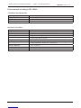
Fig. 2.7. Screen 6. Units of measurement.
Soft key Name Range/value Default value Description
1 LANGUAGE English, French, Spanish,
German, Norwegian
English Screen language selection.
2 DEPTH Meters, feet, fathoms,
braccias
Meters Unit of measurement for depth.
3 VESSEL SPD Knots, km/h, mi/h Knots Unit of measurement for vessel speed.
4 SOUND SPD m/s, knots, km/h, mi/h, ft/s m/s Unit of measurement for sound speed.
5 Not used.
6 Not used.

Page 19 of 74
SKIPPER Electronics AS
Version: 2012-05-10 Sw 1.12.6
GDS102 Operation and Installation Manual Chapter: 2 Operation
Fig. 2.8. Screen 7. Interface setup screen.
Soft key Name Range/value Default
value
Description
1 (Optional) ENABLE Pos/neg Positive Selection of polarity of remote sounding control signal.
Note: This function is operative, if remote sounding
control option is installed.
2 PULSE 100, 200, 400, 2000/nm 200/nm The number of pulses per nautical mile. Setup for pulse
input that can be connected to a speed log.
3 ANA UPPER 0 - 49 m 0 m Analogue output shallow limit, depth value
corresponding to 0 V (4 mA) on the analogue output.
4 ANA LOWER 1 - 5000 m 50 m Analogue output deep limit, depth value corresponding
to 10 V (20 mA) on the analogue output.
5 ALARM ID 0 - 999 0 Alarm identier, used in NMEA alarm sentences to be
recognized by the listener. See “NMEA Setup” on page
48 for more information about alarm sentences format.
6 MAX RANGE 200 m
500 m
1000 m
1500 m
5000 m
500 m Selection of maximal operating range. The maximal
detectable depth is dependant on the frequency and
properties of the transducer. This setting can be used to
avoid unnecessary high range adjustments by the range
key.

Page 20 of 74
SKIPPER Electronics AS
Version: 2012-05-10 Sw 1.12.6
GDS102 Operation and Installation Manual
Chapter: 2 Operation
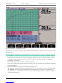
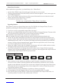
Fig. 2.9. Screen 8. Recordings selection and play back.
If recording mode is activated, the depth and all essential navigational data along with echo sounder settings will be written into
the les on the Compact Flash disk. The left half of this screen (recordings directory) represents the list of the recorded les
which are sorted by the time of the recordings. The left part of the directory represents the date and hour of the recorded data,
while the right part - minutes of the hour/date, which have been chosen by the cursor in the left part. The cursor is indicated by a
bar and can be advanced by “REC. HOUR” and “REC. MIN” soft keys. A group is dened by setting the rst recording (soft key
SELECT rst) and the last recording (SELECT last). The selected rst and last recordings are indicated in the bottom part of the
directory.
Example: Suppose we need to play back the information which has been recorded between 12.Sep.2009 12:08 and 17 Sep.2009
10:38.
• Advance the bar in the left part of the directory by using soft key “REC. HOUR next” on the position 12.Sep.09 12:xx
• Advance the bar in the right part of the directory on the position 12:08 by using soft key “REC. MIN next”
• Press “SELECT rst” soft key. The group’s rst recording is now selected.
• Advance the bar in the right part of the directory on the position 10:38 by using soft key “REC. MIN next”
• Press “SELECT last” soft key. The group’s last recording is now selected.
It is now possible to start a playback. The name of currently displayed recording is indicated in the upper part of the screen.
Note: Playback and recording functions cannot be activated at the same time.
Soft
key
Name Range/value Default value Description
1 REC. HOUR Next Advance cursor to the next hour of recordings in the directory.
2 REC. MIN Next Advance cursor to the next minute of recordings in the directory.
3 SELECT First Select group’s rst recording.
4 SELECT Last Select group’s last recording.
5 RECORDING On/off On Toggles recording mode.
6 PLAY BACK On/off Off Toggles playback mode.
Page is loading ...
Page is loading ...
Page is loading ...
Page is loading ...
Page is loading ...
Page is loading ...
Page is loading ...
Page is loading ...
Page is loading ...
Page is loading ...
Page is loading ...
Page is loading ...
Page is loading ...
Page is loading ...
Page is loading ...
Page is loading ...
Page is loading ...
Page is loading ...
Page is loading ...
Page is loading ...
Page is loading ...
Page is loading ...
Page is loading ...
Page is loading ...
Page is loading ...
Page is loading ...
Page is loading ...
Page is loading ...
Page is loading ...
Page is loading ...
Page is loading ...
Page is loading ...
Page is loading ...
Page is loading ...
Page is loading ...
Page is loading ...
Page is loading ...
Page is loading ...
Page is loading ...
Page is loading ...
Page is loading ...
Page is loading ...
Page is loading ...
Page is loading ...
Page is loading ...
Page is loading ...
Page is loading ...
Page is loading ...
Page is loading ...
Page is loading ...
Page is loading ...
Page is loading ...
Page is loading ...
Page is loading ...
-
 1
1
-
 2
2
-
 3
3
-
 4
4
-
 5
5
-
 6
6
-
 7
7
-
 8
8
-
 9
9
-
 10
10
-
 11
11
-
 12
12
-
 13
13
-
 14
14
-
 15
15
-
 16
16
-
 17
17
-
 18
18
-
 19
19
-
 20
20
-
 21
21
-
 22
22
-
 23
23
-
 24
24
-
 25
25
-
 26
26
-
 27
27
-
 28
28
-
 29
29
-
 30
30
-
 31
31
-
 32
32
-
 33
33
-
 34
34
-
 35
35
-
 36
36
-
 37
37
-
 38
38
-
 39
39
-
 40
40
-
 41
41
-
 42
42
-
 43
43
-
 44
44
-
 45
45
-
 46
46
-
 47
47
-
 48
48
-
 49
49
-
 50
50
-
 51
51
-
 52
52
-
 53
53
-
 54
54
-
 55
55
-
 56
56
-
 57
57
-
 58
58
-
 59
59
-
 60
60
-
 61
61
-
 62
62
-
 63
63
-
 64
64
-
 65
65
-
 66
66
-
 67
67
-
 68
68
-
 69
69
-
 70
70
-
 71
71
-
 72
72
-
 73
73
-
 74
74


