Page is loading ...

BIOS
Reference
Manual
REV. May 2020
Harrier
(VL-EPU-4011)
A credit-card sized system
featuring error correcting memory
(ECC), TPM security, dual or
quad core Apollo Lake processor,
and plenty of on-board I/O.

VL-EPU-4011 BIOS Reference Manual ii
WWW.VERSALOGIC.COM
12100 SW Tualatin Road
Tualatin, OR 97062-7341
(503) 747-2261
Fax (971) 224-4708
Copyright © 2020 VersaLogic Corp. All rights reserved.
Notice:
Although every effort has been made to ensure this document is error-free, VersaLogic makes no
representations or warranties with respect to this product and specifically disclaims any implied warranties
of merchantability or fitness for any particular purpose.
VersaLogic reserves the right to revise this product and associated documentation at any time without
obligation to notify anyone of such changes.
* Other names and brands may be claimed as the property of others.

iii VL-EPU-4011 BIOS Reference Manual
Product Revision Notes
Revision 1.0 Initial draft
Support Page
The Harrier Product Page contains additional information and resources for this product including:
• Operating system information and software drivers
• Data sheets and manufacturers links for chips used in this product
• BIOS information and upgrades
Customer Support
If you are unable to solve a problem after reading this manual, visiting the product support page or contact
VersaLogic Technical Support at (503) 747-2261. VersaLogic support engineers are also available via e-
mail at [email protected].
Repair Service
If your product requires service, you must obtain a Returned Material Authorization (RMA) number by
calling 503-747-2261. Be ready to provide the following information:
• Your name, the name of your company, your phone number, and e-mail address
• The name of a technician or engineer that can be contacted if any questions arise
• The quantity of items being returned
• The model and serial number (barcode) of each item
• A detailed description of the problem
• Steps you have taken to resolve or recreate the problem
• The return shipping address
AS9100 All AS9100 products dispositioned for scrap shall be conspicuously and permanently marked, or
positively controlled, until physically rendered unusable.
Material designated for scrap may be recycled in a manner that complies with applicable environmental
regulations.
Note: VersaLogic recommends that all materials be disposed of in environmentally responsible manner i.e.,
recycling in compliance with applicable laws and regulations.
Warranty Repair All parts and labor charges are covered, including return shipping charges for
FedEx Ground delivery to United States addresses.
Non-warranty Repair All approved non-warranty repairs are subject to diagnosis and labor charges,
parts charges and return shipping fees. Specify the shipping method you
prefer and provide a purchase order number for invoicing the repair.
Note:
Mark the RMA number provided by VersaLogic clearly on the outside of the box before returning.

VL-EPU-4011 BIOS Reference Manual iv
Cautions
Electrostatic Discharge
CAUTION:
Electrostatic discharge (ESD) can damage circuit boards, disk drives, and other
components. The circuit board must only be handled at an ESD workstation. If an
approved station is not available, some measure of protection can be provided by
wearing a grounded antistatic wrist strap. Keep all plastic away from the board, and do
not slide the board over any surface.
After removing the board from its protective wrapper, place the board on a grounded,
static-free surface, component side up. Use an antistatic foam pad if available.
The board should also be protected inside a closed metallic antistatic envelope during
shipment or storage.
Note:
The exterior coating on some metallic antistatic bags is sufficiently conductive to cause
excessive battery drain if the bag comes in contact with the bottom side of the Owl.
Handling Care
CAUTION:
Avoid touching the exposed circuitry with your fingers when handling the board. Though
it will not damage the circuitry, it is possible that small amounts of oil or perspiration on
the skin could have enough conductivity to cause the contents of CMOS RAM to
become corrupted through careless handling, resulting in CMOS resetting to factory
defaults.
Earth Ground Requirement
CAUTION:
All mounting standoffs should be connected to earth ground (chassis ground). This
provides proper grounding for EMI purposes.

v VL-EPU-4011 BIOS Reference Manual
Contents
Cautions ............................................................................................................................. iv
Electrostatic Discharge ......................................................................................... iv
Handling Care ....................................................................................................... iv
Earth Ground Requirement ................................................................................... iv
Introduction ................................................................................................................... 7
Features ............................................................................................................................... 7
Technical Specifications ..................................................................................................... 9
EPU-4011 BIOS Overview ........................................................................................... 10
BIOS Help ......................................................................................................................... 10
Main Menu .................................................................................................................... 11
Main Menu→Boot Features ............................................................................................. 11
Main Menu→ Network Stack ........................................................................................... 14
Main Menu→ SMBIOS Event Log .................................................................................. 15
System Setup ............................................................................................................... 15
System Setup→CPU Configuration ................................................................................. 15
System Setup→ CPU Configuration→CPU Power Management.................................... 17
System Setup→Uncore Configuration ............................................................................. 20
System Setup→South Cluster Configuration→HD-Audio Configuration ....................... 25
System Setup→South Cluster Configuration→GMM Configuration .............................. 27
System Setup→South Cluster Configuration→ISH Configuration ................................. 29
System Setup→South Cluster Configuration→LPSS Configuration............................... 30
System Setup→South Cluster Configuration→PCI Express Configuration .................... 35
System Setup→PCI Express Root Port [1-6] ................................................................... 36
System Setup→South Cluster Configuration→SATA Drives ---- Chipset-SATA
Controller Configuration ---- ............................................................................................ 43
System Setup→South Cluster Configuration→SCC Configuration ................................ 47
System Setup→South Cluster Configuration→USB Configuration ................................ 48
System Setup→South Cluster Configuration→Miscellaneous Configuration ................ 50
System Setup→Boot ......................................................................................................... 52
System Setup→Security Configuration ............................................................................ 53
System Setup→Thermal ................................................................................................... 54
System Setup→System Component ................................................................................. 57
System Setup→Debug Configuration .............................................................................. 59
System Setup→NPK Debug Configuration ..................................................................... 63
System Setup→ACPI Settings .......................................................................................... 66
System Setup→Intel(R) UltraBook Event Support .......................................................... 68
System Setup→PEP Constraints Configuration ............................................................... 69
System Setup→RTD3 settings ......................................................................................... 73
System Setup→Memory ECC Error Logging .................................................................. 77
Security ........................................................................................................................ 77
Security→TPM Configuration ......................................................................................... 78
Security→Secure Boot Configuration .............................................................................. 81

VL-EPU-4011 BIOS Reference Manual vi
VersaLogic Features ................................................................................................... 81
VersaLogic Features→UART Configuration ................................................................... 81
VersaLogic Features→PCI IRQ Routing Configuration .................................................. 86
IPv4 Network Configuration ....................................................................................... 89
IPv6 Network Configuration ....................................................................................... 89
IPv6 Network Configuration→IPv6 Current Setting ....................................................... 89
Figures
Figure 1. The Harrier (VL-EPU-4011) ........................................................................................................... 7
Tables
Table 1. Top-level Menu Bar Features .......................................................................................................... 10
Table 2. BIOS Setup Program Function Keys ............................................................................................... 10

Introduction
7 VL-EPU-4011 BIOS Reference Manual
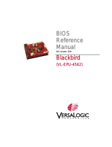
Introduction
Figure 1. The Harrier (VL-EPU-4011)
Features
The Harrier is an extremely small and rugged SWaP-optimized embedded computer. It
has been engineered and tested to meet the industry’s need for smaller, lighter and
lower power embedded systems. Slightly larger in size than a credit card and one inch
thick, the Harrier is a member of VersaLogic’s family of small, ultra-rugged embedded
x86 computers. Equipped with a powerful dual- or quad-core Intel “Apollo Lake”
processor and soldered-on ECC RAM, the Harrier is designed to withstand extreme
temperature, impact, and vibration.
Up to 8 GB of soldered-on Error Correcting Code (ECC) memory is available for high-
reliability applications. ECC memory is beneficial in environments where single bit
memory errors may occur, such as with cosmic ray interactions which increase
dramatically with altitude.

Introduction
VL-EPU-4011 BIOS Reference Manual 8
A TPM 2.0 chip is included for hardware-based security.
On-board I/O includes dual Gigabit Ethernet, one USB 3.0 and four USB 2.0 ports, and
two serial ports. SATA interface, eMMC Flash options, and a microSD socket provide a
range of data storage options. Dual Mini PCIe sockets accommodate plug-in A/D, Wi-Fi
modems, GPS receivers, MIL-STD-1553, Ethernet, Firewire, and other mini cards.
The Harrier is designed and tested for full industrial temperature (-40º to +85ºC)
operation and meets MIL-STD-202H specifications for shock and vibration. It also
features an on-board voltage regulation for dependable operation from nominal 12V
sources.

Introduction
9 VL-EPU-4011 BIOS Reference Manual
VersaLogic’s 10+ year product life support programs ensure long-term availability. This
avoids expensive upgrades and migrations that come from short, disposable lifecycle
products. Its features include:
Intel Atom* Apollo Lake
processor with up to 2 GHz burst
clock rate. Quad- or dual-core
options. Low power consumption.
Up to 8 GB soldered-down
DDR3L ECC RAM enhances
system reliability.
Dual GbE Ethernet interfaces.
Autodetect 10BaseT /
100BaseTX / 1000BaseT.
Remote boot support.
Integrated high-performance
video. Intel HD Graphics 505 with
18 Execution Units (EPU-4011-
EDP) or Intel HD Graphics 500
with 12 Execution Units (EPU-
4011-EAP). Turbo Boost.
Supports DirectX 12, OpenGL
4.4, Quick Sync Video, Clear
Video HD Technology, Clear
Video Technology, VP8, VP9,
MPEG2, H.264, H.265, and
VC1.Fanless operation
Fanless operation
SATA port supports bootable SATA
hard drive
Full- and half-size sockets.
Supports Wi-Fi modems, GPS,
MIL-STD-1553, Ethernet, flash
data storage, and other mini PCIe
modules.
One USB 3.0 port and four USB
2.0 ports support keyboard,
mouse, and other devices.
Eight 3.3V digital I/O lines, three
8254 timer/counters and I2C
support.
Supports removable microSD card
solid-state drives.
RoHS compliant
Extended temperature operation
Customization available
The Harrier is compatible with popular operating systems.
Technical Specifications
Refer to the Harrier Data Sheet for complete specifications. Specifications are subject to
change without notification.

EPU-4011 BIOS Overview
VL-EPU-4011 BIOS Reference Manual 10
EPU-4011 BIOS Overview
To access the BIOS Setup program, press during the early boot cycle. The top-level
menu bar is shown below.
Table 1. Top-level Menu Bar Features
Menu Function
Main
Displays processor and memory parameters
System Setup Configures advanced features, including CPU, IDE, and USB
Security Sets passwords and security features
VersaLogic
Features UART and PCI IRQ routing configuration
IPv4 Network
Configuration
IPv6 Network
Configuration Current Setting
The following table lists the function keys available for menu screens.
Table 2. BIOS Setup Program Function Keys
Key
Function
Key
Function
or Selects a different menu screen
(Moves the cursor left or right)
or Selects an item (Moves the
cursor up or down)
or Changes option/field
Executes a command or selects
a sub-menu
Go to next page
Go to previous page
Go to top of screen
Go to bottom of screen
Select field
General help
Load Previous Settings
Loads optimal defaults
Loads failsafe default values
Exit
Save and exit
BIOS Help
Press the “F1” key anywhere in the Setup Utility to get the General Help page. BIOS
menu options are listed which includes a brief description of those options.

Main Menu
11 VL-EPU-4011 BIOS Reference Manual
Main Menu
Main Menu→Boot Features
Option: NumLock:
On (default)
Off
Details: Selects Power-on state for NumLock.
Option: Timeout
Minimum = 0x0000
Maximum = 0x0063
Default = 0x0000
Details: Number of seconds that P.O.S.T will wait for the user input before booting.
Option: CSM Support
No
Yes (default)
Details: Compatibility Support Module that provide backward compatibility services for
legacy BIOS services, like int10/int13, dependent OS.
Option: Quick Boot
Disabled (default)
Enabled
Details: Enable/Disable quick boot.
Option: Diagnostic Splash Screen
Disabled (default)
Enabled
Details: If you select 'Enabled' the diagnostic splash screen always displays during boot.
If you select 'Disabled' the diagnostic splash screen does not display unless you press
HOTKEY during boot.

Main Menu
VL-EPU-4011 BIOS Reference Manual 12
Option: Diagnostic Summary Screen
Disabled (default)
Enabled
Details: Display the Diagnostic summary screen during boot.
Option: BIOS Level USB
Disabled
Enabled (default)
Details: Enable/Disable all BIOS support for USB in order to reduce boot time. Note that
this will prevent using a USB keyboard in setup or a USB biometric scanner such as a
finger print reader to control access to setup, but does not prevent the operating system
from supporting such hardware.
Option: USB Legacy
Disabled
Enabled (default)
Details: Enable/Disable USB BIOS SMM support for mouse, keyboard, mass storage,
etc, in legacy operating systems such as DOS.
Option: Console Redirection
Disabled (default)
Enabled
Details: Enable/Disable Universal Console Redirection.
Option:Terminal Type
ANSI (default)
VT100
VT100+
UTF8
Details: Set terminal type of UCR.

Main Menu
13 VL-EPU-4011 BIOS Reference Manual
Option: Baudrate
9600
19200
38400
57600
115200 (default)
Details: Set baudrate of UCR.
Option: Flow Control
None (default)
RTS/CTS
XON/XOFF
Details: Set flow control method for UCR.
None - No flow control.
RTS/CTS - Harware flow control.
XON/XOFF - Software flow control.
Option: Continue C.R. after POST
Disabled
Enabled (default)
Details: Enables Console Redirection after OS has loaded.
Option: Allow Hotkey in S4 resume
Disabled
Enabled (default)
Details: Enable hotkey detection when system resuming from Hibernate state
Option: UEFI Boot
Disabled
Enabled (default)
Details: Enable the UEFI boot.

Main Menu
VL-EPU-4011 BIOS Reference Manual 14
Option: Legacy Boot
Disabled
Enabled (default)
Details: Enable the Legacy boot.
Option: Boot in Legacy Video Mode
Disabled (default)
Enabled
Details: Enable to force the display adapter to switch the video mode to Text Mode 3 at
the end of BIOS POST for non-UEFI boot mode (Legacy Boot). Some legacy software,
such as DUET, requires that the BIOS explicitly enter text video mode prior to boot.
Option: Load OPROM
All
On Demand (default)
Details: Load all OPROMs or on demand according to the boot device.
Main Menu→ Network Stack
Option: Network Stack
Disabled (default)
Enabled
Details: Enable/Disable UEFI Network Stack
Option: IPv4
Disabled
Enabled (default)
Details: Enable/Disable IPv4
Option: IPv6
Disabled
Enabled (default)
Details: Enable/Disable IPv6

System Setup
15 VL-EPU-4011 BIOS Reference Manual
Option: UEFI PXE Boot Priority
IPv6 First
IPv4 First (default)
Details: Set the priority of UEFI PXE Boot
Main Menu→ SMBIOS Event Log
Option: Event Log
Disabled
Enabled (default)
Details: Enable/Disable Event Log.
System Setup
System Setup→CPU Configuration
Option: Bi-directional PROCHOT#
Disable
Enable (default)
Details: When a processor thermal sensor trips (either core), the PROCHOT# will be
driven.
If bi-direction is enabled, external agents can drive PROCHOT# to throttle the
processor.
Option: VTX-2
Disable
Enable (default)
Details: To enable or disable the VTX-2 Mode support
Option: VT-d
Disable (default)
Enable
Details: Enable/Disable VT-d, Please disable IPU when you want to enable VT-D feature

System Setup
VL-EPU-4011 BIOS Reference Manual 16
Option: TM1
Disable
Enable (default)
Details: Enable/Disable TM1
Option: DTS
Disable (default)
Enable
Details: Enabled/Disable Digital Thermal Sensor
Option: Active Processor Cores
Disable (default)
Enable
Details: Enable this to disable core in each processor package
Option: Core 0
Enable (default)
Details: Core 0 Enable
Option: Core 1
Disable
Enable (default)
Details: Core 1 Enable/Disable
Option: Core 2
Disable
Enable (default)
Details: Core 2 Enable/Disable
Option: Core 3
Disable
Enable (default)
Details: Core 3 Enable/Disable

System Setup
17 VL-EPU-4011 BIOS Reference Manual
Option: Monitor Mwait
Disable
Enable
Auto (default)
Details: Enable/Disable Monitor Mwait. If Auto is selected, Monitor Mwait will be disabled
for Linux/Yocto OS with B1 silicon. For the rest Monitor Mwait will be enabled.
System Setup→ CPU Configuration→CPU Power
Management
---- System Power Options ----
Option: Intel(R) SpeedStep(tm)
Disable
Enable (default)
Details: Allows more than two frequency ranges to be supported.
Option: Boot performance mode
Max Performance (default)
Max Battery
Details: Select the performance state that the BIOS will set before OS handoff.
Option: Intel® Turbo Boost Technology
Disable
Enable (default)
Details: Enable to automatically allow processor cores to run faster than the base
operating frequency if it's operating below power, current, and temperature specification
limits.
Option: C-States
Disable
Enable (default)
Details: Enable/Disable C States

System Setup
VL-EPU-4011 BIOS Reference Manual 18
Option: Enhanced C-states
Disable
Enable (default)
Details: Enable/Disable C1E. When enabled, CPU will switch to minimum speed when
all cores enter C-State.
Option: Max Package C State
S0ix default (default)
PC2
C0
Details: This option controls the Max Package C State that the processor will support.
Option: Max Core C State
Fused value (default)
Core C10
Core C9
Core C8
Core C7
Core C6
Core C1
Unlimited
Details: This option controls the Max Core C State that cores will support.
Option: C-State Auto Demotion
Disabled
C1 (default)
Details: Configure C-State Auto Demotion
Option: C-State Un-demotion
Disabled
C1 (default)
Details: Configure C-State Un-demotion

System Setup
19 VL-EPU-4011 BIOS Reference Manual
Option: Power Limit 1 Enable
Disabled
Enabled (default)
Details: Enable/Disable Power Limit 1
Option: Power Limit 1 Clamp Mode
Disabled
Enabled (default)
Details: Enable/Disable Power Limit 1 Clamp Mode
Option: Power Limit 1 Power
Auto (default)
6
7
8
...
23
24
25
Details: Power Limit 1 in Watts. Auto will program Power Limit 1 based on silicon default
support value

System Setup
VL-EPU-4011 BIOS Reference Manual 20
Option: Power Limit 1 Time Window
Auto (default)
1
2
3
...
96
112
128
Details: Power Limit 1 Time Window Value in Seconds. Auto will program Power Limit 1
Time Window based on silicon default support value
System Setup→Uncore Configuration
---- GOP Configuration ----
Option: GOP Driver
Enable (default)
Disable
Details: Enable GOP Driver will unload VBIOS; Disable it will load VBIOS
Option: Intel Graphics Pei Display Peim
Enable
Disable (default)
Details: Enable/Disable Pei (Early) Display
---- IGD Configuration ----
Option: Integrated Graphics Device
Disable
Enable (default)
Details: Enable : Enable Integrated Graphics Device (IGD) when selected as the
Primary Video Adaptor. Disable: Alwarys disable IGD
/