GE TIER1-FH-10-45-PLEATED-KIT User manual
- Category
- Sanitary ware
- Type
- User manual

Water Filter
Installation and Operating Instructions
Specifications
Tools Required
Screw dri ver Fi l e Pi pe Cut t er or Hacksaw
2 Adj ust able Wrenches Pencil
Materials Required
Depends on t ype, si ze, and l ocat i on of pi pe on w hi ch syst em w i l l be i nst al l ed. See i nst r uct i ons t hat r el at e t o your
particul ar instal lati on, or consul t your l ocal hardware st ore or pl umbi ng suppl i er t o find out more about your particul ar
installation needs.
Precautions
WARNING: Do not use w i t h w at er t hat i s mi cr obi ol ogi cal l y unsaf e or of unknow n qual i t y w i t hout adequat e di si nf ect i on
before or after t he syst em.
CAU TION: Fi l t e r m ust be p r ot e ct e d a g ai nst f r ee z i ng , w h i ch c a n c aus e c r a ck i ng of t he f i l t er a nd w a t er l e ak age .
CAU TION: The r ubber o- r i ng pr ovi des t he w at er - t i ght seal bet w een t he cap and t he bot t om of t he housi ng. I t i s i mpor t ant
that the o-ring be properly seated in the groove below the threads of the housing, or a water leak could occur.
CAU TION: To pr e v e n t cos t l y r e p a i r s o r p o s s i b l e w a t e r dama g e t h e s u mp o f pl a s t i c h o u s i n g s m u s t b e r e p l a c e d e v e r y f i v e
years f or clear, and t en years f or opaque. If sump is ol der t han recommended, repl ace immedi atel y. Dat e sump for reference
and i ndi cate repl acement dat e.
•Install on cold water line only.
•Do not install where system will be exposed to direct sunlight.
•Make certain that installation complies with all state and local laws and regulations.
•For prolonged periods of non-use (such as during a vacation), it is recommended that the system be flushed
thoroughly. Let water run for 5–6 minutes before using.
•The filter cartridge has a limited service life. A decrease in water flow indicates that the cartridge should be
replaced.
•Some harmless bacteria will attack cellulose media cartridges. If your cartridge seems to disintegrate or has a musty
or moldy odor, swi t ch t o a synthet i c media cart ridge or consul t t he cartri dge manufacturer.
1
Filter Housing Temperat ure Range Pressure Range Opt ional Accessories
3/4-inch I/O 40–125°F (4.4–51.7°C) 30-125 psi (2.1-8.62 bar) Mounting Bracket (151011)
Spanner Wrench (150295)
1/4, 3/8, 1/2-inch 40–125°F (4.4–51.7°C) 30-125 psi (2.1-8.62 bar) Mounting Bracket (244047)
I/O Spanner Wrench (150539)
1-inch, 1-1/2-inch 40–100°F (4.4–37.8°C) 30-100 psi (2.1-6.89 bar) Mounting Bracket (150062)
I/O Spanner Wrench (150296)

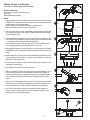
Whole House Installation
(1/ 2 inch or 3/ 4-inch main cold water line)
Materials Required:
(2) 3/ 4-i nch or 1/ 2-i nch NPT compression f it ti ngs
Te f l o n
®
tape
Red uci ng a da pt er s (i f ne ces sa r y)
NOTE:
•Reducing adapters can be used to adapt the filter to different pipe sizes. See your local
hardware st ore or pl umbing st ore f or hel p i n sel ect ing the necessary adapters and com-
pression f it t ings f or your inst al lat ion needs.
•Galvanized fittings must be used with installation on galvanized pipe.
•Filter must be installed after water meter or pressure tank.
1. Turn off cold water supply and open nearest faucet to drai n pi pes bef ore st art ing instal -
lation. Wrap about 6 inches of Teflon
®
tape in clockwise direction around pipe threads
of each compressi on f i tt ing.
2. If mount i ng bracket (not suppl i ed) i s t o be used, first use bracket as a t empl ate t o mark
screw l ocati ons. Then place bracket over cap and al ign with inl et and out let port s. Al low
1-
1
/
2 inch clearance below housing to enable cartridge changes.
NOTE: Mounting bracket for heavy-duty filter does not fit over inlet/ outlet connec-
tions. Heavy-duty bracket should be screwed directly into cap or filter.
3. St art compressi on f it t ings i nto cap by hand and use a wrench to t ight en fi rml y. DO NOT
OV ERT I GH T EN. A bo ut o ne t hr ead s ho ul d r e m ai n v i s i bl e. Rem o ve com pr es si on nu t s f r om
fittings.
4. Measure l ength (shown as X on Fi gure 4) across assembl ed f itt ings and subtract 1 i nch
if you are installing on 3/4-inch pipe or 1
1
/
2 inches if you are installing on 1/2-inch pipe.
Mark section of pipe to be removed.
5. Use a pi pe cutt er or hacksaw, cut pi pe and remove marked sect ion of pi pe. Fi le or sand
sharp edges on remai ning pipe.
6. Sl ip compressi on nut and ferrul e ont o each end of pi pe.
7. Ali gn fi l ter assembl y wi th ends of pipe, maki ng cert ai n cap opening marked “ IN” is f ac-
ing your incoming water supply. It will be necessary to spread ends of pipe apart to
install filter assembly. Using two adjustable wrenches, hold incoming adapter securely
with one wrench and tighten nut with second wrench. Repeat process for outgoing
adapter.
8. Sl owl y turn on the water suppl y t o al low fil ter t o f il l wi th water, t hen press t he red pres-
sure-rel ief butt on on top of fil ter to release trapped air. Open nearest faucet and f lush
water through cartridge for 5 minutes. Check for leaks before leaving installation.
9. CAU TION : If water pipes are used to ground electrical systems, appliances, or
phones, be cert ain t o i nstal l a jumper wi re. Contact a qualif ied el ectri cian with any
questi ons about your home’s electri cal syst em.
1
4
5
6
3
2
x
2
IN
OUT
8
7
9
x

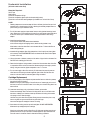
Undersink Installation
(3/ 8-inch cold water line)
Materials Required:
Te f l o n
®
tape
Pl ast i c t ub i n g
(2) 3/ 8-i nch compressi on f itt ings
(2) 3/ 8-i nch compressi on el bows (wi th f errul es and tubing i nserts)
(2) 3/ 8-i nch t o 3/ 4-i nch NPT reducing adapters (for i nstal lat ion of 3/ 4-inch I/ Os / f il ters)
NOTE:
•Reducing adapters can be used to adapt the filter to different pipe sizes. See your local
hardware st ore or pl umbing st ore f or hel p i n sel ect ing the necessary adapters and com-
pression f it t ings f or your inst al lat ion needs.
1. Turn off cold water supply and open nearest faucet to drai n pi pes bef ore st art ing instal -
lation. Place a tray or towel under the cold water line to catch excess water. Wrap about
6 i nches of Tef l on
®
tape in clockwise direction around pipe threads of each fitting /
adapter.
2. Att ach the mounti ng bracket:
3/ 4-inch f il t ers–see #2 under Whol e House Inst al lat ion
3/ 8-inch f il t ers–usi ng t he self -tapping screws, at t ach mounti ng bracket to cap.
Mark location under sink where filter is to be mounted. Allow
1
1
/
2
inches under filter to
enable cart ridge changes.
3. Assembl e f itt ings/ adapt ers. Start f itt ing/ adapt er i nt o i nlet of cap by hand, t hen t ight en
with a wrench. DO NOT OVERTIGHTEN. About one thread should remain visible. Repeat
for outlet on filter cap.
4. Usi ng a pi pe cut ter or hacksaw, remove a 3-i nch secti on of pi pe f rom the cold wat er l ine.
Debur r ends of r emai ni ng pi pe w i t h a f i l e.
5. Det ermine t he l engths of t ubing needed to connect t he i nlet and out let sides of t he f ilt er
to compression elbows on the cold water line. Measure tubing short enough to prevent
kinki ng. Using t wo wrenches, t ight en compressi on nut s 1
1
/
2- to 2-turns.
6. Turn on wat er suppl y to al low f il ter to sl owl y fi l l with water, t hen press t he pressure-
relief button on the housing to release trapped air. Open faucet and flush filter with
water for 5-minutes. Check for leaks and tighten fittings as needed.
Cart ridge Replacement
A. Turn off wat er suppl y t o f il ter. Depress red pressure-rel ief but ton t o rel ieve the pressure,
then twist off bottom of housing.
NOTE: If turning off water supply to filter will also turn off water supply to the rest of
the home, be sure to fill a bucket of water first to allow you to clean housing after it has
been removed.
B. Locat e and r emove l ar ge o- r i ng, w i pe cl ean of l ubr i cant , and set asi de.
Di scar d used car t r i dge. Ri nse out bot t om of housi ng and f i l l about 1/ 3 f ul l w i t h w at er.
Add about 1 tablespoon of bl each and scrub cap and bott om of housi ng with nonabra-
sive sponge or cl oth. Rinse thoroughly.
Lubr i cat e o- r i ng w i t h cl ean si l i cone gr ease. Cl ean gr oove and connect i on poi nt on cap.
Insert o-ring back into groove and smooth into place with finger.
Insert new cartridge over standpipe in bottom of housing.
C. S cr e w b ot t om of housi ng o nt o t he c ap an d h an d- t i ght en . D O N OT OV ER- T I GH T EN.
Make certain cap standpipe slips into cartridge.
Sl ow l y t ur n on t he w at er suppl y t o al l ow f i l t er t o f i l l w i t h w at er and t hen pr ess t he r ed
pressure-reli ef but ton on top of t he f ilt er t o rel ease trapped ai r. Open f aucet and flush
filter with water for 5-minutes. Check for leaks before leaving installation.
1
4
5
6
3
2
IN
3”
cold w ater
line
nut
ferrule
elbow
OUT
3

Scal e & Co ar s e Sand, Di r t , Fi ne san d, Ex t r a - f i ne san d,
rust particles sand silt dirt, silt dirt, silt
P5 5 m i c r on nom . S p u n Po l yp r o p yl e n e 10 gpm / < 1 p s i 2 m o. ••• ••
CP- 5 5 m i c r o n n o m . Pl ea t ed Cel l ul o se / Po l y 1 0 g p m / < 1p s i 2 m o . ••• ••
CW- F 1 0 mi c r o n n o m. C o r d - W o u n d 7 g p m/ < 1 p s i 3 mo . ••• •
S1 20 mi cr on nom. Pl ea t e d Ce l l ul o se 1 0 gp m/ < 1 psi 4 mo. •••
CW- M F
30 micron nom. Cord-wound 10 gpm/ < 1 psi 3 mo. •••
R30 30 m i c r on n o m . Pl e a t ed pol y es t e r 12 gpm / < 1 psi 4 m o. •••
R50 50 m i c r on n o m . Pl e a t ed pol y es t e r 12 gpm / < 1 psi 4 m o. ••
Tr o u b l e s h o o t i n g
Leaks…Bet w een cap and bottom of housing:
1. Turn off water supply and press the red pressure-rel ief but ton.
2. Cl ean and l ubri cate o-ri ng if necessary, then screw bot tom of housi ng
onto cap and hand-t ight en. DO NOT OVER-TIGHTEN.
4
Mfg. By Pentair Water Treatment ® 2003
145817 Rev B 10/ 03
WARRANTY
Pen t ek w a r r an t s t o t h e or i gi n a l ow ner ( un d er n or mal u s e) : a l l p r od u ct s and p a r t s t o be f r ee f r om d e f e c t s i n m a t er i al an d w o r km anshi p f or a peri od of one (1) year. Notwi t hstandi ng t he f oregoi ng, (a) t he warrant y peri od f or sumps shal l be a peri od of f ive (5) years. Any
replacement products furnished will be free from defects in material and/or workmanship for the remainder of the original warrant y peri od, or 30 days, whi chever i s l onger. Thi s warrant y does not cover: (1) cart ri dges, media, and accessori es (2) defect s not report ed
within the above time period, (3) items manufactured by other companies, (4) problems arising from failure to comply with Pentek i nstruct ions, (5) probl ems and/ or damage ari sing from act s of nature, abuse, misuse, negl i gence or acci dent by any part y ot her than Pentek,
(6) probl ems and/ or damage resul ti ng i n whol e or in part f rom al terat i on, modi fi cat ion, repai r or att empted al t erat ion, modif icat i on or repai r by any part y ot her t han Pent ek, (7) noncompl i ance wi th appli cabl e codes/ ordi nances. If a def ect i n workmanship and/ or materi al
in a product or part covered by the warranty should arise, Pentek, at its sole discretion, will repair or replace the defective product or part (Pentek may consider, in good faith, the customer's preference).
Al l clai med def ecti ve product must : (1) be aut hori zed f or ret urn by Pent ek wi t h an RGA number (2) incl ude proof of t he purchase date of the product or part (3) returned to Pentek prior to the expiration of the warranty date, at the customer's expense, shipment pre-paid,
(4) be accompani ed by a l ett er det ai li ng t he Model Number, Seri al Number (i f any), and a bri ef descri pti on of t he probl em. TO THE M A XI M UM EXTEN T PERM I TTED BY A PPLI CABLE LAW, PENTEK DI SCLA I M S A LL OTHER WA RRAN TI ES, W HETHER EXPRESS OR I M PLI ED,
INCLUDING, BUT NOT LIMITED TO, THE IMPLIED WARRANTY OF MERCHANTABILITY AND FITNESS FOR A PARTICULAR PURPOSE, WITH REGARD TO THE PRODUCTS, PARTS AND ANY ACCOMPANYING WRITTEN MATERIALS.
To t h e ma x i mu m e x t e n t p e r mi t t e d b y a p p l i c a b l e l a w , Pe n t e k s h a l l n o t b e l i a b l e f o r a n y d a ma g e s w h a t s o e v e r ( i n c l ud i ng , bu t no t l i mi t e d t o , l o s s o f t i me , i n co n ve ni e nc e , e xp en se s , l ab or o r ma t e r i al c h ar g es i nc u r r e d i n c o nn ec t i o n w i t h t h e r e mo va l o r r e p l a c eme nt of t he
product s or part s, special , i ncident al , consequent ial , or i ndi rect damages f or personal i nj ury, loss of business prof it s, business int errupt ion, l oss of busi ness i nf ormati on, or any ot her pecuni ary l oss) ari sing out of t he use of or i nabil i ty to use t he def ecti ve product s or part s,
even i f Pent ek has been advi sed of t he possi bil i ty of such damages. Pent eks' maxi mum l i abil i ty under any provi sion of thi s Limited Warranty shall be limited to the amount actually paid for the products or parts. NOTE: Because some states do not allow the exclusi on or
limitation of incidental or consequential damages, the above limitations or exclusions may not apply. THIS WARRANTY GRANTS SPECIFIC LEGAL RIGHTS, AND OTHER RIGHTS MAY APPLY. SUCH RIGHTS VARY FROM STATE TO STATE.
PENTEK FILTRATION
502 Indiana Avenue • Sheboygan, WI 53081
To l l Fr ee Tech n i c a l Su p p o r t : 80 0 - 861-8758 • Tech n i ca l S u p p o r t : 920-451-93 0 1 • su p p o r t sp eci al i st @p en t ek f i l t r at i o n .co m
Phon e 920-457-9435 • w w w.p entekf i l tr at i o n.co m
International Fax: 920-457-2417 • international@pentekfiltration.com
Chl o r i ne
Bad Tast e Sedi me nt
Ta s t e & Od o r
C1 5 m i c r o n n o m . Car b o n - i m p r eg n at ed 5 gpm / 2 ps i 3 m o. • • •
Cel l ul ose
CC- 1 0 — Gr a n u l ar A c t i v a t ed Car b o n 1 gpm / 3 p s i 6 m o. • •
(coconut-shel l )
GAC- 1 0 — Gr anu l ar Act i v a t e d Car b o n 1 gpm / 3 p s i 6 m o. • •
CB C
®
-10 .5 micron nom. Activated Carbon Block 1 gpm/< 2 psi 12 mo. • • •
Scal e and Co ar s e Sand, di r t , Fi ne san d, Ex t r a - f i ne san d,
Rust p a r t i cl e s s an d si l t d i r t , si l t di r t , s i l t
CP5- B B 5 m i c r o n n o m . Pl e a t e d Cel l u l ose / Pol ye s t er 20 g p m / < 1 p s i 3 m o .
••• ••
S1- BB 20 mi cr on nom. Pl eat ed Cel l ul ose 20 g pm/ < 1 p si 4 mo.
•••
R30- B B 30 m i c r on no m . Pl e a t e d Pol yest e r 25 gpm / < 1 ps i 6 m o .
•••
R50- B B 50 m i c r on no m . Pl e a t e d Pol yest e r 25 gpm / < 1 ps i 6 m o .
••
Chl o r i n e B a d Tas t e S e di m en t
Ta s t e & O d o r & O d or
RFC- B B 25 m i c r on n o m . Gr a n u l ar A c t i v a t ed Car b o n 10 gpm / 1 p s i 3 m o. •••
On unit inlet/ outlet connections:
1. Turn off water supply. Tighten compressi on fi tt ings wi th a wrench.
DO NOT OVERTI GHTEN.
2.
Tu r n o n w a t e r s u p p l y. I f l e ak s p e r s i s t , o r i f t he r e a r e o t h e r l ea k s o n u ni t , t u r n o f f
water supply.
Cal l Pen t ek Tec hn i cal S upp or t a t 1- 8 00- 86 1- 87 58.
Replacem ent Filter Cartridges
WHOLE HOUSE Sediment Cartridges
UNDERSINK DRINKING Water Cartridges
HEAVY-DUTY Cartridges
Model Filtration Filter Material / Max Flow Rate/ Filter
Ra t i ng Cons tr uc t i on Pr e ssur e Dr op Li f e *
Model Filtration Filter Material / Max Flow Rate/ Filter
Ra t i ng Cons tr uc t i on Pr e ssur e Dr op Li f e *
Model Filtration Filter Material / Max Flow Rate/ Filter
Ra t i ng Cons tr uc t i on Pr e ssur e Dr op Li f e *
Reduces:
Reduces:
Reduces:
* Filter life depends on usage
and water condi tions.
-
 1
1
-
 2
2
-
 3
3
-
 4
4


GE TIER1-FH-10-45-PLEATED-KIT User manual
- Category
- Sanitary ware
- Type
- User manual
Ask a question and I''ll find the answer in the document
Finding information in a document is now easier with AI
Related papers
Other documents
-
Aquasana FS-SC-10-R Operating instructions
-
Pentek PENTEK-150574 User manual
-
vitapur VPS1140-1 User guide
-
 Express Water FLTWH1045C02 User manual
-
 Express Water WH200SCS User manual
-
 Express Water WH100SP User manual
-
 SMARDY PRO 203 User manual
-
 ReplacementBrand PENTEK-PCC-106 User manual
-
Pentek ST-BC-10 User manual
-


