Page is loading ...

For more eective and safer operation and
to prolong the life of the heater, read the
Owner’s Guide and follow the instructions.
Failure to properly maintain the heater will
void any warranty and may cause the
heater to function improperly.
LIMITED ONE YEAR WARRANTY: Cadet
will repair or replace any Cadet T521 or
T522 thermostat found to be defective
within one year after the date of purchase.
These warranties do not apply:
1. Damage occurs to the product through
improper installation or incorrect supply
voltage;
2. Damage occurs to the product through
improper maintenance, misuse, abuse,
accident, or alteration;
3. The use of unauthorized accessories or
unauthorized components constitutes
an alteration and voids all warranties.
Refer to Cadet website or call
customer service at 855.223.3887 or
360.693.2505 for list of authorized
accessories and components.
4. Cadet’s warranty is limited to repair or
replacement.
5. In the event Cadet elects to replace
any part of your Cadet product, the
replacement parts are subject to the
same warranties as the product. The
installation of replacement parts does
not modify or extend the underlying
warranties. Replacement or repair of any
Cadet product or part does not create
any new warranties.
If you believe your Cadet product is
defective, please contact Cadet during the
warranty period, for instructions on how to
have the repair or replacement processed.
Parts and Service
Visit cadetheat.com/parts-service for
information on where to obtain parts and
service.
1. Turn the thermostat knob all the way to the right.
2. When the room reaches your comfort level, turn the knob to the left, just until
it clicks and the heater turns o. The heater will automatically keep the room
temperature at this setting.
3. To reduce the room temperature, turn the knob to the left. To increase the
room temperature, turn the knob to the right.
T521: Turning the knob all the way to the left sets the temperature at about 41°F.
T522: Turning the knob all the way to the left turns the heater o.
WARRANTY
OPERATING INSTRUCTIONS
Make sure all wires are properly connected and installation is complete before
you turn on the heater. Turn power back on at the main disconnect panel.
OWNER’S GUIDE
T521 T522
WALL THERMOSTAT
http://cadetheat.com/install/t5
For how-to videos or more information, please visit:
ESPAÑOL ver la guía del propietario en cadetheat.com/espanol/t5
cadetheat.com
855.CADET.US
Vancouver, Washington
tested to UL standards
Rev 08/01/17 #720135
©2017 Cadet
INSTALLATION INSTRUCTIONS
A. Connect the two black thermo-
stat wires to the two loose heater
wires.
B. Connect the two supply wires to
the two red thermostat wires.
C. Connect the copper ground
supply wire to the copper wire going
to the heater.
DOUBLE POLE (4-WIRE) - 120 VOLT
Proceed to OPERATING INSTRUCTIONS.
Thank you for your purchase! Question or problem? Let us solve
it with a single phone call, email or online chat! We’ll save you a
trip back to the store!
Phone: 855.CADET.US (855.223.3887)
email: [email protected]
Live chat: cadetheat.com (contact us)
Cadet Customer Service
A
A
B
B
C
FROM
POWER
SUPPLY
TO
HEATER

IMPORTANT INSTRUCTIONS
WORKING WITH ELECTRICITY
REQUIRED TOOLS
Straight
and Phillips
Screwdrivers
Wire Strippers Wire
Connectors
Volt Meter
®
®
®
®
If you are uncomfortable working with electricity, running electrical supply wire
or installing a circuit breaker, please consult a licensed electrician.
Unanswered questions? Call our technical support team in Vancouver,
Washington at 855.223.3887 or outside the USA 360.693.2505.
®
1. Read all instructions before
installing or using this thermostat.
2. Use this thermostat only as
described in this manual. Any
other use not recommended by
the manufacturer may cause re,
electric shock, or injury to persons.
3. Do not insert or allow foreign
objects to enter any ventilation
or exhaust opening as this may
cause an electric shock or re, or
damage the thermostat.
4. To disconnect thermostat turn o
power to heater circuit at main
disconnect panel.
5. Do not operate any thermostat
after it malfunctions. Disconnect
power at main disconnect panel
and have thermostat inspected
by a qualied electrician before
reusing.
6. A thermostat has arcing or
sparking parts inside. Do not use
in areas where gasoline, paint, or
ammable liquids are stored.
When using electrical appliances, basic precautions should always be
followed to reduce the risk of re, electric shock, and injury to persons, including
the following:
1. WARNING: All electrical work and
materials must comply with the
National Electric Code (NEC), the
Occupational Safety and Health
Act (OSHA), and all state and
local codes.
2. WARNING: Make sure all wire
connections to the thermostat
are correct and tight to prevent
electrical shorts. Use appropriate
wire to meet NEC and local codes
for rated power consumption.
3. Use copper conductors only.
4. Turn o power to heater at main
disconnect panel.
5. Use wire connectors (not included)
for all connections.
6. An electrical outlet box is required.
INSTALLATION INSTRUCTIONS
• Verify power has been turned o before starting any work!
• Follow the instructions in the Owner’s Guide included with your heater until
prompted to make thermostat connections.
TIPS BEFORE YOU BEGIN
A. Connect one supply wire to the
red thermostat wire.
B. Connect the black thermostat
wire to one of the heater wires.
C. Connect the remaining supply
wire to the remaining heater wire.
Wrap supply (white) wire with black
tape to identify it as hot!
D. Connect the copper ground
supply wire to the copper wire
going to the heater.
A. Connect the two black thermo-
stat wires to the two loose heater
wires.
B. Connect the two hot supply
wires to the two red thermostat
wires.
Wrap supply (white) wire with black
tape to identify it as hot!
C. Connect the copper ground
supply wire to the copper wire going
to the heater.
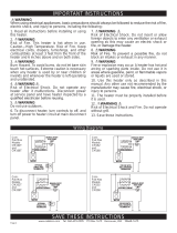
SINGLE POLE (2-WIRE) - 240 or 208 VOLT
SINGLE POLE (2-WIRE) - 120 VOLT
DOUBLE POLE (4-WIRE) - 240 or 208 VOLT
A. Connect the hot supply wire to
the red thermostat wire.
B. Connect the black thermostat
wire to the hot supply wire going to
the heater.
C. Connect the remaining neutral
supply wire to the remaining wire
going to the heater.
D. Connect the copper ground
supply wire to the copper wire
going to the heater.
Proceed to OPERATING INSTRUCTIONS.
Proceed to OPERATING INSTRUCTIONS.
Proceed to OPERATING INSTRUCTIONS.
ELECTRICAL RATINGS
120 vac - 22 amps 1/6 hp
208-240 vac - 22 amps 1/6 hp
277 vac - 18 amps 1/6 hp
A
B
C
D
A
B
C
D
A
A
B
B
C
FROM
POWER
SUPPLY
TO
HEATER
FROM
POWER
SUPPLY
TO
HEATER
FROM
POWER
SUPPLY
TO
HEATER
/