All disclosures, notices and warranty conditions are being written on the back of the box. Released on 16
th
of June, 2011.
Installation and mounting manuals for EK-MOSFET Sabertooth P67 water block:
This product is intended for installation only by expert users. Please consult with a qualified technician for installation. Improper installation may result in damage to your equipment. EK Water Blocks assumes no liability
whatsoever, expressed or implied, for the use of these products, nor their installation. The following instructions are subject to change without notice. Please visit our web site at www.ekwaterblocks.com for updates.
Before installation of this product please read any important notice, disclosure and warranty conditions printed on the back of the box and on EKWB home page.
EKWB recommends using EK-PSC fittings which require a small amount of force to screw them in; otherwise fittings might break or damage your block. These fittings do not need to be tightened
with much force because the liquid seal is made using rubber gaskets. Use of corrosive inhibitors is highly recommended.
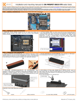
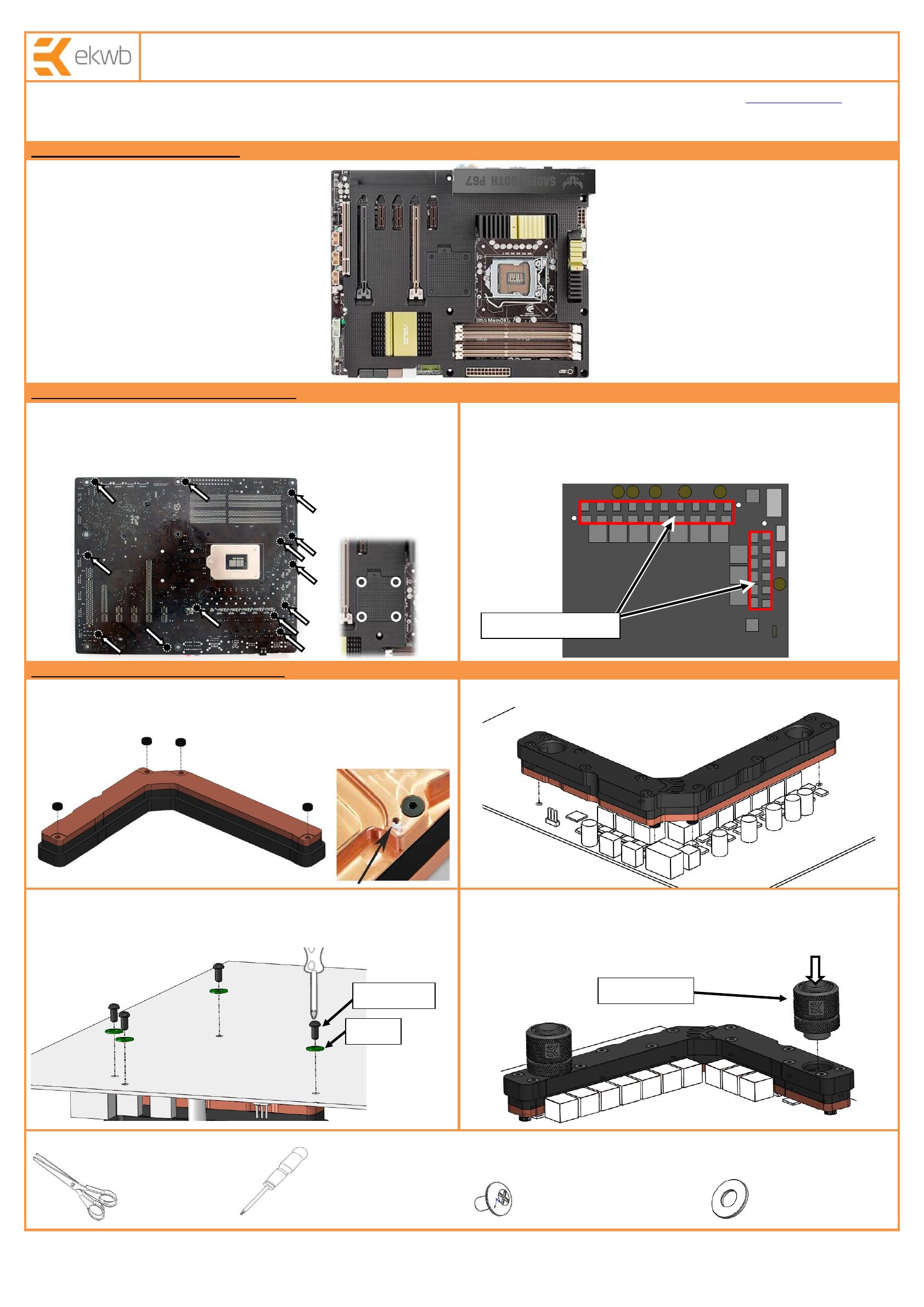
STEP 1: GENERAL INFORMATION. Sample picture of ASUS Sabertooth P67 motherboard.
STEP 2: PREPARING YOUR MOTHERBOARD
1. REMOVING STOCK COOLER. Remove all four (4) screws pins holding the
MOSFET heat-sink assembly as well as nine (9) screws holding the plastic thermal
shield to the motherboard. Both MOSFET heat sinks as well as thermal shield should
be removed. There are also four (4) screws in front of the motherboard holding the
plastic thermal shield to the circuit board which need to be removed.
2. CUTTING THERMAL PADS. Your block comes with two precut thermal pads
(90x15x1mm), which have to be trimmed and placed on MOSFET chips. EK
recommends using small drops of electrically non-conductive (for example: Arctic
Cooling MX-2 ™ or MX-4 ™) thermal grease on each phase regulator (that is being
covered with thermal pad; see picture below) in order to even further improve the
thermal performance of the water block.
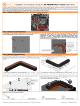
STEP 3: PREPARING YOUR WATERBLOCK
1. PLACING STANDOFFS ON WATERBLOCK. Your waterblock comes with 4
standoffs (height 2,1 mm) that prevent overtightening of screws. Nonetheless avoid
using excessive mounting force. To ensure standoffs stay in place you are encouraged
to use small amount of thermal grease on standoffs, thus making them adhesive.
2. PLACING WATERBLOCK ON MOTHERBOARD. Place waterblock on VRM section
of the motherboard’s circuit board as shown on picture below:
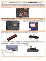
3. ATTACHING WATERBLOCK ON MOTHERBOARD. When waterblock is safely
placed on motherboard, please align the openings and fasten the waterblock using the
enclosed M3x6 screws and plastic washers to the motherboard’s circuit board. It is
recommended that you check for unwanted contacts before powering up the system.
4. POSITIONING FITTINGS AND CONNECTING TO WATER CIRCUIT. Attach the
liquid cooling tubes and connect the water-block(s) into the cooling circuit. To ensure
that the tubes are securely attached to the barb/fittings, please use hose clamps or an
appropriate substitute. The use of an algaecide and corrosion inhibitors is always
recommended for any liquid cooling system.
You can use any opening as an inlet/outlet port.
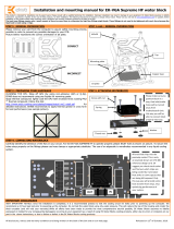
REQUIRED TOOLS AND MOUNTING SCREWS:
scissors philips screwdriver 4x screws M3x6 DIN7985 4x PVC M3 washers