Plus Data Projector User manual
- Category
- Data projectors
- Type
- User manual
This manual is also suitable for

ACCESS
ENTER
C
ANC
E
L
SELECT
+
-
P
O
W
E
R
P
O
W
E
R
S
T
A
T
U
S
A
U
T
O
S
O
U
R
C
E
M
E
N
U
R
GB
DVI
O
N
O
FF
FR
EE
ZE MU
TE
E
CO
DVI
R
G
B
V
IDE
O
S-V
IDEO
Q
UICK
ZOOM
VOL
KSTN
CANCEL
MENU
A
SP
ECT A
UTO
PO
W
E
R
ENTER
TIMER
IMPORTANT
* DLP™ (Digital Light Processing) and DMD (Digital Micromirror Device) are registered trademarks of Texas Instru-
ments Incorporated (U.S.A.).
* DMD is an ultra-precise part developed by Texas Instruments (U.S.A.) which takes the place of liquid crystal (in the
projector).
*VGA and XGA are trademarks or registered trademarks of International Business Machines Corporation (U.S.A.).
* S-VGA is a registered trademark of Video Electronics Standards Association.
* Microsoft, Windows, and PowerPoint are registered trademarks of Microsoft Corporation (U.S.A. and other countries).
* Macintosh is a trademark of Apple Computer Inc. (U.S.A.).
* TMDS is a trademark of Silicon Image, Inc.
Note that even in the absence of explanatory notes, serious attention is paid to the trademarks of the various companies
and to the product trademarks.
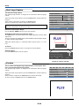
DATA PROJECTOR
U2-1200/U2-817
User’s Manual

E-2
IMPORTANT SAFETY INFORMATION
Precautions
Please read this manual carefully before using your PLUS U2-1200/U2-817 Data Projector and keep the manual
handy for future reference.
CAUTION
TO PREVENT SHOCK, DO NOT OPEN THE CABINET. NO USER-SERVICEABLE PARTS INSIDE. REFER
SERVICING TO QUALIFIED PLUS SERVICE PERSONNEL.
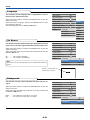
This symbol warns the user that uninsulated voltage within the unit may have sufficient magnitude
to cause electric shock. Therefore, it is dangerous to make any kind of contact with any part inside
of this unit.
This symbol alerts the user that important literature concerning the operation and maintenance of
this unit has been included. Therefore, it should be read carefully in order to avoid any problems.
The above cautions are given on the bottom of the product.
WARNING
TO PREVENT FIRE OR SHOCK, DO NOT EXPOSE THIS UNIT TO RAIN OR MOISTURE. DO NOT USE
THIS UNIT’S GROUNDED PLUG WITH AN EXTENSION CORD OR IN AN OUTLET UNLESS ALL THREE
PRONGS CAN BE FULLY INSERTED. DO NOT OPEN THE CABINET. THERE ARE HIGH-VOLTAGE COM-
PONENTS INSIDE. ALL SERVICING MUST BE DONE BY QUALIFIED PLUS SERVICE PERSONNEL.
WARNING
This is a class A product. In a domestic environment this product may cause radio interference in which case
the user may be required to take adequate measures.
RF Interference
WARNING
The Federal Communications Commission does not allow any modifications or changes to the unit EXCEPT
those specified by PLUS Vision in this manual. Failure to comply with this government regulation could void
your right to operate this equipment.
This equipment has been tested and found to comply with the limits for a Class A digital device, pursuant to
Part 15 of the FCC Rules. These limits are designed to provide reasonable protection against harmful interfer-
ence when the equipment is operated in a commercial environment. This equipment generates, uses, and can
radiate radio frequency energy and, if not installed and used in accordance with the instruction manual, may
cause harmful interference to radio communications. Operation of this equipment in a residential area is likely
to cause harmful interference in which case the user will be required to correct the interference at his own
expense.
DOC Compliance Notice
This Class A digital apparatus meets all requirements of the Canadian Interference-Causing Equipment Regula-
tions.

E-3
Important Safeguards
These safety instructions are to ensure the long life of the unit and to prevent fire and shock. Please read them
carefully and heed all warnings.
Installation
•For best results, use the unit in a darkened room.
• Place the unit on a flat, level surface in a dry area away from dust and moisture.
• Do not place the unit in direct sunlight, near heaters or heat radiating appliances.
• Exposure to direct sunlight, smoke or steam can harm internal components.
• Handle the unit carefully. Dropping or jarring can damage internal components.
• Do not place heavy objects on top of the unit.
Power Supply
• The unit is designed to operate on a power supply of 100 - 240 V 50/60 Hz AC. Ensure that your power supply
fits these requirements before attempting to use the unit.
•For PLUGGABLE EQUIPMENT, the socket-outlet shall be installed near the equipment and shall be acces-
sible.
• Handle the power cable carefully and avoid excessive bending. A damaged cord can cause electric shock or
fire.
• Disconnect the power cable (mains lead) from the power outlet after using the unit.
Before disconnecting the power cable, make sure that the POWER indicator lights in amber (not blinking or in
green).
Cleaning
• Disconnect the power cable (mains lead) from the unit.
• Clean the cabinet of the unit periodically with a damp cloth. If heavily soiled, use a mild detergent. Never use
strong detergents or solvents such as alcohol or thinner.
• Use a blower or lens paper to clean the lens, and be careful not to scratch or mar the lens.
• Clean the ventilation slots and speaker grills on the unit periodically using a vacuum cleaner. If accumulated
dust blocks the ventilation slots, the unit will overheat, which may cause the unit to malfunction.
Use a soft brush attachment when using the vacuum cleaner. Do not use a hard attachment, such as a crevice
tool, to prevent the damage to the unit.
Lamp Replacement
• Be sure to replace the lamp when the Status indicator comes on. If you continue to use the lamp after 3000
hours of usage, the lamp will turn off.
Fire and Shock Precautions
• Ensure that there is sufficient ventilation and that vents are unobstructed to prevent the buildup of heat inside
the unit. Allow at least 10 cm (3 inches) of space between the unit and walls.
• Prevent foreign objects such as paper clips and bits of paper from falling into the unit. Do not attempt to retrieve
any objects that fell into the unit. Do not insert any metal objects such as a wire or screwdriver into the unit. If
something should fall into the unit, immediately disconnect the power cable from the unit and have the object
removed by a qualified PLUS service person.
• Do not place any liquids on top of the unit.
• Do not look into the lens while the unit is on. Serious damage to your eyes could result.
Carrying around
When carrying the unit around, please use the carrying case that comes with it and, to protect the lens from
scratches, always shut the sliding lens cap. Also, do not subject the unit to strong mechanical shock.
IMPORTANT SAFETY INFORMATION

E-4
Major Features
Book-sized, lightweight (at about 2.5 kg/5.5 lb) high-intensity mobile projector
The synergy of the DLP™ (Digital Light Processing) display system and our own optical design serve to improve the optical
utilization efficiency. The three primary colors (RGB) required in color expression are reproduced with one DMD (Digital
Micromirror Device of high precision). These factors have enabled a design that offers both high intensity and small size/
lightweight features.
Sharp, clear picture
The DLP display system affords RGB color fidelity and inconspicuous gaps between the individual dots, thereby permitting
the display of small characters and diagrams with distinct clarity.
Powerful functions for presentations
A wide variety of easy-to-set functions have been built into the projector, from a digital keystone correction function (used
when making settings) that corrects picture distortion, to an auto adjustment function that automatically identifies the PC
signal.
A presentation timer that supports presentations and a startup logo creation function that permits unhindered logo creation
have also been added.
High contrast ration of 1500:1
Use of a new generation of DMD devices has given birth to an amazing 1500:1 high contrast ratio.
By widening the difference of brightness between black and white, you can see a degree of sharpness that is greater than just
the brightness based on specifications.
Beautiful reproduction of high-quality images from DVD
Faithful reproduction of color tones gives rise to the display of natural images. High-quality images such as those from DVD
and digital high-definition television broadcasts bring out the display capabilities that are an essential strength of the DLP
display system projector.
Enable RGB output in addition to digital/analog RGB input...
by using a DVI cable to connect the projector with a personal computer equipped with a DVI connector. This will allow fully
digital pictures to be enjoyed.
Also, by using the RGB output connector, the same image can be sent to the monitor of a personal computer.
Econo-mode switch function for the lamp output
Using the lamp Econo-mode will extend the life of the lamp and lower the power consumption.
By switching the lamp mode to suit your operating environment, you will save on lamp cost as well as contribute to energy
conservation and ecology.

E-5
Table of Contents
IMPORTANT SAFETY INFORMATION ................................................................................... E-2
Major Features ....................................................................................................................... E-4
Table of Contents ................................................................................................................... E-5
Checking the Supplied Accessories .................................................................................... E-7
Names of the Main Unit Parts ............................................................................................... E-9
Names of the Remote Control Parts ................................................................................... E-11
Preparing the Remote Control ............................................................................................ E-12
Button Battery Replacement ..................................................................................... E-12
Remote Control Range ............................................................................................. E-12
The Procedure Up to Projecting to the Screen ................................................................. E-13
Placement Guide .................................................................................................................. E-14
U2-1200 Screen Size and Projection Distance ......................................................... E-14
U2-817 Screen Size and Projection Distance ........................................................... E-15
Connecting Personal Computers and Video Equipment .................................................. E-16
Connections with Personal Computer ....................................................................... E-16
Personal Computers with a DVI Connector ......................................................... E-16
Personal Computers with a Mini D-Sub 15-Pin Connector ................................. E-17
To Output the External Output Signal of a Notebook Computer ......................... E-18
Connections with Composite Signals ........................................................................ E-19
Video Equipment with VIDEO Connectors .......................................................... E-19
Video Equipment with S-VIDEO Connectors ...................................................... E-19
Connections with Component Signals ....................................................................... E-20
When the Video Equipment Has a YCbCr Connector or YPbPr Connector ........ E-20
Connections with the AUDIO Jack ............................................................................ E-21
Connections with the RGB OUT Connector .............................................................. E-22
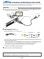
Power Cable Connections and Switching the Power On/Off ........................................... E-23
Operating ................................................................................................................... E-23
Finishing .................................................................................................................... E-25
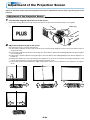
Adjustment of the Projection Screen ................................................................................. E-26
Adjustment of the Projection Screen ......................................................................... E-26
Making Adjustments with the Adjusters .............................................................. E-27
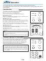
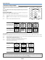
General Operation ................................................................................................................ E-28
Input Selection .......................................................................................................... E-28
Automatic Adjustment of Analog RGB ...................................................................... E-28
Selection of Aspect Ratio .......................................................................................... E-29
Freezing a Moving Picture ......................................................................................... E-30
Cancelling Video and Audio Temporarily ................................................................... E-30
Lamp Mode ............................................................................................................... E-30
Using the Presentation Timer .................................................................................... E-31
Keystone .................................................................................................................... E-32
Adjustment of the Volume .......................................................................................... E-32
Enlargement of the Image and Video Movement ...................................................... E-33
Using the Quick Menu ............................................................................................... E-34
Menu Operation Method ...................................................................................................... E-35
Performing Menu Operations .................................................................................... E-37
List of Item Names Offering Input Selection and Adjustments/Settings .................... E-40
Picture ................................................................................................................................... E-42
Brightness / Contrast / Color / Tint / Sharpness ........................................................ E-42
Picture Adj. / Fine Picture / H Position / V Position .................................................... E-42
Reset ......................................................................................................................... E-43

E-6
Table of Contents
Color ...................................................................................................................................... E-44
Gamma ..................................................................................................................... E-44
Color Temp. ............................................................................................................... E-44
White ......................................................................................................................... E-44
Color Space .............................................................................................................. E-45
White Balance ........................................................................................................... E-45
View ....................................................................................................................................... E-46
Aspect ....................................................................................................................... E-46
Filter .......................................................................................................................... E-46
Vertical Flip ................................................................................................................ E-47
Keystone .................................................................................................................... E-47
Keystone Save .......................................................................................................... E-47
Setup ..................................................................................................................................... E-48
Auto Source............................................................................................................... E-48
Auto Power Off .......................................................................................................... E-48
Menu Position ............................................................................................................ E-48
Lamp Mode ............................................................................................................... E-49
Input Format .............................................................................................................. E-49
Presentation Timer .................................................................................................... E-50
Logo Background ...................................................................................................... E-50
Logo Scaling ............................................................................................................. E-50
Logo Position ............................................................................................................. E-51
Capture Mode ........................................................................................................... E-51
Invalidata Logo .......................................................................................................... E-51
Start Logo Capture .................................................................................................... E-52
Preview ...................................................................................................................... E-52
Language .................................................................................................................. E-53
On Screen ................................................................................................................. E-53
Background ............................................................................................................... E-53
Startup Screen .......................................................................................................... E-54
Info......................................................................................................................................... E-55
Status ........................................................................................................................ E-55
Factory Default .......................................................................................................... E-55
Lamp Timer Reset ..................................................................................................... E-55
Resolution / Frequency ............................................................................................. E-56
Lamp Timer ............................................................................................................... E-56
Startup Logo Creation ......................................................................................................... E-57
When an Indicator is Lit or Flashing .................................................................................. E-59
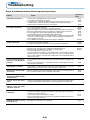
Troubleshooting ................................................................................................................... E-60
Cleaning ................................................................................................................................ E-61
Replacing the Lamp Cartridge ............................................................................................ E-62
Specifications ....................................................................................................................... E-65
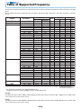
Table of Supported Frequency ........................................................................................... E-66
Cabinet Dimensions ............................................................................................................ E-67

E-7
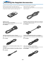
Checking the Supplied Accessories
Remove the main unit and the accessories from the box and check that the following items are included.
Remote control (includes one button battery) [1]
This controls the projector. Please remove the transportation
insulation sheet at time of purchase. (See Page E-12.)
Power cable (1.8 m / 5.9 feet) [1]
This power cable supplies power to the unit. See Page E-23
about connections.
DVI / Mini D-sub 15-pin conversion cable (18 cm / 0.6 feet) [1]
This is used in making connections with a personal computer.
See Page E-17 about connections.
No. 772708000
RGB signal cable
(Mini D-sub 15-pin, 2 m / 6.6 feet) [1]
This is used in making connections with a personal computer.
See Page E-17 about connections.
No. 772709000
S-Video cable (Mini DIN 4-pin plug, 2 m / 6.6 feet) [1]
This cable is used in the connection of video equipment that
has an S-video connector. Connections are described on Page
E-19.
No. 771709000
Video cable (RCA pin plug, 2 m / 6.6 feet) [1]
This cable is used in the connection of video equipment that
has a video connector. Connections are described on Page E-
19.
No. 771703000
Audio conversion cable (Mini plug / RCA pin plug, 15 cm /
0.5 feet) [1]
This cable is used with equipment whose audio connector is
of the phono pin type. Connections are described on Page E-
21.
No. 770704000
Audio cable (Mini plug, 2 m / 6.6 feet) [1]
This cable is used with equipment that has phono type audio
jacks. Connections are described on Page E-21.
No. 769710000
O
N
OFF
FR
E
EZ
E
M
UT
E
EC
O
DVI
RG
B
V
IDE
O
S-VIDE
O
Q
UIC
K
E
N
T
E
R
Z
O
O
M
CANCEL
ASPE
CT
AUTO
POW
ER
TIMER
KS
T
N
V
O
L
MENU

E-8
Carrying case (for projector and accessories) [1]
This is a case designed for storing the projector and its
accessories.
Use this carrying case when storing or moving the pro-
jector.
User's Manual (CD-ROM edition) [1]
User's Manual (Simplified Edition) [1]
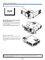
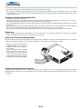
HOW TO PUT THE PROJECTOR INTO THE CARRYING CASE
Attach the lens cap to the projector before putting the pro-
jector into the carrying case, and then fasten the velcro
strap. Put accessories into the pocket.
Pocket
Velcro strap
Checking the Supplied Accessories

E-9
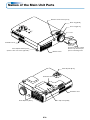
Names of the Main Unit Parts
ACCESS
E
N
T
E
R
CANCEL
SELECT
+
-
POWER
POWER
STATUS
AUTO
SOURCE
MENU
Front adjuster button [E-27]
(There is also one on the right side.)
Ventilation slots
Remote control sensor [E-12]
Zoom ring [E-26]
Focus ring [E-27]
Lens
Lens cap
To protect the lens, attach
the lens cap when the pro-
jector is not being used.
Exhaust vents
Front adjusters [E-27]
Ventilation slots
Rear adjuster [E-27]
Ventilation slots
Lamp cover [E-63]

E-10
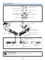
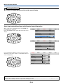
Names of the Main Unit Parts
RGB OUTAUDIOVIDEOS-VIDEO
ACCESS
ENTER
CANCEL
SELECT
+
-
POW
ER
PO
W
ER
STATUS
AUTO
SOURCE
ME
NU
R
GB
DVI
AUDIO
VIDEO
S-VIDEO
R
G
B
O
U
T
RGBDVI
ENTER
CANCEL
SELECT
POWER
POWER
STATUS
AUTO
SOURCE
MENU
ACCESS
POWER indicator [E-23,59]
STATUS indicator [E-23,59]
AUTO button [E-28]
Buttons used in menu
and toolbar operations
[E-24,34,35]
ENTER button
POWER button [E-23]
SOURCE button [E-28]
MENU button
SELECT ▲▼
buttons
CANCEL button
Built-in Security Slot
This security slot supports the MicroSaver Security System manufactured by
Kensington Microware Inc.
Ventilation slots
Speaker
Built-in security slot
(See description below.)
AC IN connector [E-23]
Remote control sensor [E-12]
Ventilation slots
DVI connector [E-16,17]
RGB connector [E-17,20]
S-VIDEO connector [E-19]
VIDEO connector [E-19]
AUDIO connector [E-21]
RGB OUT connector
[E-22]
ACCESS indicator [E-12]

E-11
ON OFF
FREEZE MUTE ECO
DVI RGB
VIDEO S-VIDEO
QUICK
ZOOM
CANCEL
ASPECT AUTO
POWER
TIMER
KSTN
VOL
MENU
ENTER
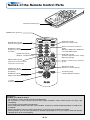
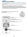
Names of the Remote Control Parts
ON
OFF
FREEZE
MUTE
ECO
DVI RGB
VIDEO
S-VIDEO
QUICK
ENTER
ZOOM
CANCEL
ASPECT
AUTO
POWER
TIMER
KSTN
MENU
Infrared transmitter [E-12]
VOL button [E-32]
(Volume adjustment display)
Precautions
Handling of the Remote Control
* Do not drop the remote control or handle it inappropriately.
* Do not expose the remote control to water or other liquids. Should the remote control become wet, wipe it dry
immediately.
*Try to avoid use in hot and/or humid locations.
* Please keep button batteries out of the reach of children. If a battery is swallowed, promptly obtain the medical care
of a doctor.
* Remove the batteries from the remote control when it is not going to be used for a long period.
* Some operations (such as menu operations) are available only through the use of the remote control and attention
should be given to its careful handling.
POWER button [E-23,25]
FREEZE button [E-30]
(Freezes moving pictures)
MUTE button [E-30]
(Temporarily cancels the video
and audio)
ASPECT button [E-29]
(Selects the vertical and hori-
zontal ratio of the screen)
QUICK button [E-34]
(Displays a simplified menu)
TIMER button [E-31]
(Presentation timer time set-
ting display)
ZOOM button [E-33]
(Digital zoom adjustment display)
+/– button
(Used in all adjustments)
Buttons used for input selection
[E-28]
DVI button, RGB button, VIDEO but-
ton and S-VIDEO button
AUTO button [E-28]
(Automatic adjustment of the analog
RGB moving image)
Buttons used for menu operations
[E-35]
KSTN button [E-32]
(Keystone correction display)
ECO button [E-30]
(Selection of lamp mode)

E-12
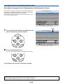
5m / 16.4 feet 7m / 23 feet
20˚
20˚
30˚
30˚
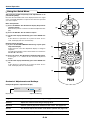
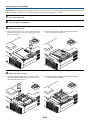
Preparing the Remote Control
Button Battery Replacement
Using the remote control for the first time
The battery compartment is fitted with a transportation insulation sheet at the time of shipping. Pull
out the sheet and remove it. The remote control is now ready for use.
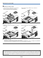
Replacement Method
1
Insert the tip of a ballpoint pen
or some other pointed object
into the hole of the battery
holder, then pull out to open.
2
Remove the old battery and in-
stall a new button battery with (+)
side facing upward in the battery
holder.
3
Insert the battery holder into the re-
mote control and push in until the
battery holder closes with a "click"
sound.
CR2025
M
n
O
2
-
L
i
C
E
L
L
3
V
O
L
T
S
J
A
P
A
N
H
CR2025
CR2025
M
n
O
2
-
L
i
C
E
L
L
3
V
O
L
T
S
J
A
P
A
N
H
CR2025
Purchase a CR2025 type battery for replacement.
CAUTION
Danger of explosion if battery is incorrectly replaced.
Replace only with the same or equivalent type (CR2025) recommended by the manufacturer.
Dispose of used batteries according to your local regulations.
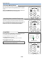
Remote Control Range
Point the infrared transmitter of the remote control toward the remote control sensor located at the front
or rear of the main unit and operate.
Reception of the remote control signal should generally be possible within the range illustrated below.
Side View
Top View
Remote control in-
frared transmitter
Remote control in-
frared transmitter
Remote con-
trol sensor
ACCESS Indicator
Function of the ACCESS Indicator
When the projector's remote control sensor receives the remote control signal, the
ACCESS indicator flashes once and the projector begins operation. If the indicator
does not flash, check the following points.
• The indicator will not flash when bright light strikes the projector's remote control
sensor or the remote control's transmitter, or when there is an obstacle located in
between that blocks the signal.
• The indicator will not flash when the button battery is exhausted.
ENTER
CANCEL
SELECT
ACCESS
Remote con-
trol sensor

E-13
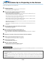
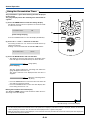
The Procedure Up to Projecting to the Screen
Perform setup adjustments in the following order.
1 Position the projector
Determine the locations to set up the screen and the projector.
See "Placement Guide" on Page E-14, 15.
2 Connect the video equipment and personal computer
Connect your equipment to the projector.
When making connections with the personal computer's DVI connector or RGB connector, see
"Connections with Personal Computers" on Page E-16.
When making connections with the video equipment's video connector or an S-video connector,
see "Connections with Composite Signals" on Page E-19.
When making connections with the video equipment's YCbCr connector or YPbPr connector,
see "Connections with Component Signals" on Page E-20.
When playing the audio through the built-in speaker of the projector, see "Connections with the
AUDIO Jack" on Page E-21.
Monitoring the analog RGB input signal, see "Connections with the RGB OUT Connector" on
Page E-22.
3 Connecting the power cable and switching on the power
See "Operating" on Page E-23.
See "Finishing" on Page E-25.
4 When selecting the language of menu displays, etc.
(Only when the power is first switched on following purchase)
See "When [Menu Language Select] Is Displayed Upon Switching On the Power" on Page E-
24.
5 Switching on the power of the personal computer and video equipment
6 Properly adjust the projection image to the screen
See "Adjustment of the Projection Screen" on Page E-26.
7 Selecting input equipment
See "Input Selection" on Page E-28.
8 Adjust the screen or video image
Adjust the image to the optimum condition as required.
See the Table of Contents for the adjustment items.
About DLP projectors
Though careful attention is paid to providing optimum quality, please note that with DLP type projectors, in rare cases there may
be black spots or bright spots among the picture elements.
Note:
* Please purchase a screen.
*A DVI-D cable (order code 28-697), which is available separately, is required for connections with the DVI connector of the personal
computer.
*A component cable (order code 28-690), which is available separately, is required to connect a DVD player or other equipment with YCbCr
connectors.
*A component cable (order code 28-690), which is available separately, is required to connect high definition (HD) video equipment or other
equipment with YPbPr connectors.

E-14
m (feet)
m
(feet)
1
(3.3)
2
(6.6)
3
(9.8)
4
(13.1)
5
(16.4)
6
(19.7)
7
(23.0)
8
(26.2)
9
(29.5)
10
(32.8)
11
(36.1)
12
(39.4)
13
(42.7)
14
(45.9)
0
1
(3.3)
2
(6.6)
3
(9.8)
4
(13.1)
5
(16.4)
6
(19.7)
h1
h2
h2
0
40"
60"
300"
27-33"
150"
120"
100"
80"
200"
250"
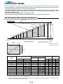
Placement Guide
* Use this information as a guide to find out about the screen size when the projector is placed at a certain location, or
to find out the approximate size of a screen that will be required.
* The projection distance (from the lens surface of the projector) within which focusing can be maintained is 1.20m /
3.94 feet to 13.81m/45.3 feet (for the U2-1200) and 1.20 m/3.94 feet to 17.70m/58.1 feet (for the U2-817). Please set up
the projector within this range.
* Refer to the projection distance table for your projector model.
* Please change the projection method for suspended projectors. See "Vertical Flip" on Page E-47.
U2-1200 Screen Size and Projection Distance
Height from center of lens to
bottom edge of the projection
Height from center of lens to
top edge of the projection
WIDE
Center of lens
Projection Distance
TELE
Screen size (Diagonal)
Width
Height
* There is a tolerance of ±5% due to design values.
* This table uses the lens apex and lens center as references and requires that the projector be in a horizontal condition
(with front and rear adjusters fully withdrawn).
27"
33"
40"
60"
80"
100"
120"
150"
200"
250"
300"
0.560.41
0.670.50
0.810.61
1.210.91
1.621.21
2.031.52
2.431.82
3.042.28
4.063.04
5.083.81
6.094.57
–- 1.20
1.23 - 1.48
1.49 - 1.80
2.26 - 2.73
3.03 - 3.65
3.80 - 4.57
4.57 - 5.50
5.73 - 6.88
7.65 - 9.19
9.57 - 11.50
11.50 - 13.81
0.48
0.59
0.72
1.07
1.43
1.79
2.14
2.68
3.58
4.48
5.38
0.07
0.09
0.11
0.16
0.22
0.27
0.32
0.40
0.54
0.67
0.81
Screen Size
Designation
(Inches)
Screen Size
Width x Height
Projection Distance
Height h1 Height h2
1.83 1.35
2.19 1.64
2.65 2.00
3.96 2.98
5.31 3.96
6.66 4.98
7.97 5.97
9.97 7.48
13.32 9.97
16.66 12.50
19.98 14.99
(m) (feet)
1.57
1.94
2.36
3.51
4.69
5.87
7.02
8.79
11.75
14.70
17.65
0.23
0.30
0.36
0.52
0.72
0.89
1.05
1.31
1.77
2.20
2.66
(m) (feet)
(m) (feet) (m) (feet)
Wide - Tele Wide - Tele
–- 3.94
4.04 - 4.86
4.89 - 5.91
7.41 - 8.96
9.94 - 11.98
12.47 - 14.99
14.99 - 18.04
18.80 - 22.57
25.10 - 30.15
31.40 - 37.73
37.73 - 45.31
Center of lens
Screen Height

E-15
m
(feet)
0
1
(3.3)
2
(6.6)
3
(9.8)
4
(13.1)
5
(16.4)
6
(19.7)
7
(23.0)
8
(26.2)
9
(29.5)
10
(32.8)
11
(36.1)
12
(39.4)
13
(42.7)
14
(45.9)
15
(49.2)
16
(52.5)
17
(55.8)
18
(59.1)
0
1
(3.3)
2
(6.6)
3
(9.8)
4
(13.1)
5
(16.4)
6
(19.7)
m
(feet)
7
(23.0)
h1
h2
h2
60"
40"
300"
21-26"
250"
200"
150"
120"
100"
80"
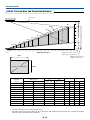
U2-817 Screen Size and Projection Distance
Height from center of lens to
bottom edge of the projection
Height from center of lens to
top edge of the projection
WIDE
Center of
lens
Projection Distance
TELE
Screen size (Diagonal)
Width
Height
* There is a tolerance of ±5% due to design values.
* This table uses the lens apex and lens center as references and requires that the projector be in a horizontal condition
(with front and rear adjusters fully withdrawn).
21"
26"
40"
60"
80"
100"
120"
150"
200"
250"
300"
0.430.32
0.530.40
0.810.61
1.210.91
1.621.21
2.031.52
2.431.82
3.042.28
4.063.04
5.083.81
6.094.57
–- 1.20
1.24 - 1.49
1.93 - 2.32
2.91 - 3.50
3.90 - 4.69
4.88 - 5.87
5.87 - 7.05
7.34 - 8.83
9.81 - 11.78
12.27 - 14.74
14.73 - 17.70
0.44
0.55
0.83
1.25
1.66
2.08
2.49
3.12
4.16
5.21
6.25
0.12
0.15
0.22
0.34
0.45
0.56
0.67
0.84
1.12
1.40
1.68
Screen Size
Designation
(Inches)
Screen Size
Width x Height
Projection Distance
Height h1 Height h2
1.41 1.05
1.74 1.31
2.66 2.00
3.97 2.99
5.31 3.97
6.66 4.99
7.97 5.97
9.97 7.48
13.3 29.97
16.67 12.50
19.98 14.99
(m) (feet)
1.44
1.80
2.72
4.10
5.45
6.82
8.17
10.24
13.65
17.09
20.51
0.39
0.49
0.72
1.12
1.48
1.84
2.20
2.76
3.67
4.59
5.51
(m) (feet)
(m) (feet) (m) (feet)
Wide - Tele Wide - Tele
Center of lens
–- 3.93
4.07 - 4.89
6.33 - 7.61
9.55 - 11.48
12.80 - 15.39
16.01 - 19.26
19.26 - 23.13
24.08 - 28.97
32.19 - 38.65
40.26 - 48.36
48.33 - 58.07
Placement Guide
Screen Height

E-16
Connecting Personal Computers and Video Equipment
Connecting this unit with a personal computer permits presentation data to be projected as a large screen display at
conferences, lectures, and on other occasions. Furthermore, connecting this unit to a DVD player or other video equip-
ment source in combination with an audio/video amplifier and speaker system will allow you to enjoy convincing home
theater.
Connections with Personal Computer
Please check the following before making connections with the personal computer.
•A suitable resolution for the U2-817 is 800 600 dots (S-VGA) and the maximum displayable resolution is XGA (1024 768
dots).
•A suitable resolution for the U2-1200 is 1024 768 dots (XGA) and the maximum displayable resolution is S-XGA (1280
1024 dots).
Make changes to a displayable resolution at the personal computer side. Please check with "Table of Supported Frequency"
on Page E-66.
• The setting method for the personal computer will differ depending on the specific model. Please read the personal computer
instruction manual or the on-line help information, or contact the manufacturer of your personal computer.
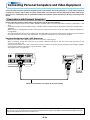
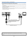
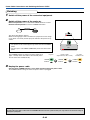
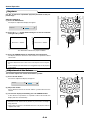
Personal Computers with a DVI Connector
• Make the connection with a DVI-D cable and the PC connector of the projector.
When connecting, arrange the connectors in the proper orientation and plug in. Turn the screw knobs and fasten to the
connector of the main unit.
• The projector has been set to "Auto" at the factory; however, if it does not project, please change the input setting to "Digital"
using the menu sequence of [Setup] → [Input Format] → [DVI].
See "Input Format" on Page E-49.
RGBDVI
MONITOR OUT
Personal
computer
DVI-D cable (Available as an option. Order code: 28-697)
Note
This projector uses a 29-pin DVI connector that supports the digital interface. Digital signal TMDS (Transition Minimized Differential Signal-
ling) of the DVI (Digital Visual Interface) standard is used.

E-17
Connecting Personal Computers and Video Equipment
Personal Computers with a Mini D-Sub 15-Pin Connector
• When connections are made to the RGB connector of this projector, make these connections using the supplied RGB signal
cable.
Please orient the connector to mate properly when before inserting it, then turn the screw knobs to secure the connector to
that of the projector.
The projector has been set to "Auto" at the factory; however, if it does not project, please change the input setting to "RGB"
using the menu sequence of [Setup] → [Input Format] → [RGB].
See "Input Format" on Page E-49.
• When making connections with the DVI connector of the projector, please make the connection via the supplied DVI/mini D-
Sub 15-pin conversion cable.
The projector has been set to "Auto" at the factory; however, if it does not project, please change the input setting to "Analog"
using the menu sequence of [Setup] → [Input Format] → [DVI].
See "Input Format" on Page E-49.
RGBDVI
MONITOR OUT
RGB signal cable (Supplied item)
Personal computer
DVI/mini D-Sub 15-pin conversion cable
(Supplied item)
RGB signal cable (Supplied item)
Note:
* Before making connections, check the power of the projector and the equipment to be connected is switched off.
* When projection will be with a notebook computer connected, knowledge will be required for the cable connection and notebook computer
startup procedure as well as the operation that follows startup. Please consult the instruction manual of your notebook computer or the on-
line help.

E-18
Connecting Personal Computers and Video Equipment
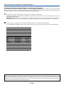
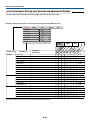
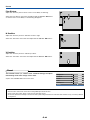
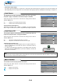
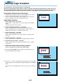
To Output the External Output Signal of a Notebook Computer
When projection will be with a notebook computer connected, knowledge will be required for the cable connection and notebook
computer startup procedure as well as the operation that follows notebook startup. Please consult the instruction manual of your
notebook computer or the on-line help while performing the following procedure.
1
Check whether a signal is being sent from the notebook computer to the projector.
An indication appearing on the liquid crystal display of the notebook computer does not necessarily mean that an external
output signal is being output.
REFERENCE: When "Resolution" or "Frequency" is not displayed under "Info." on the menu of the projector, this means that
the external output signal is not being output from the personal computer. See "Frequency /Resolution" on Page E-56.
2
Should a sign not be output from the notebook computer, please try the operation described below.
For an IBM PC/AT compatible computer, press the [Fn] key plus any one of the [F1] to [F12] keys. (See the table below.)
Manufacturer Model Key
akia All computers Fn + F2
COMPAQ All computers Fn + F4
DELL All computers Fn + F8
EPSON All computers Fn + F8
FUJITSU All computers Fn + F10
GATEWAY All computers Fn + F3
iiyama All computers Fn + F3
IBM All computers Fn + F7
NEC All computers Fn + F3
Panasonic All computers Fn + F3
SHARP All computers Fn + F5
SONY All computers Fn + F7
SOTEC All computers Fn + F3
TOSHIBA All computers Fn + F5
Victor All computers Fn + F10
Note: Table information is current to September 2002.
Note:
When the liquid crystal display of the notebook computer and the projector are displayed at the same time, the projected image might not be
correct even though the liquid crystal display shows a correct indication. Should this occur, stop the simultaneous display of the notebook
computer and try the mode with external output only. Try an operation such as that described in aforementioned Step 2 and try closing the
liquid crystal panel which might result in external output only.

E-19
Connecting Personal Computers and Video Equipment
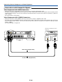
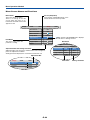
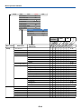
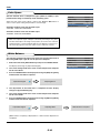
Connections with Composite Signals
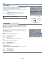
Video Equipment with VIDEO Connectors
• Make the connection to the VIDEO connector of the projector using the supplied video cable.
• The input setting of the VIDEO connector has been set to "Auto" at the factory; however, if the projector does not project, please
change the input setting to "Your Country's Television Broadcast System" using the menu sequence of [Setup] → [Input For-
mat] → [Video].
See "Input Format" on Page E-49.
Video Equipment with S-VIDEO Connectors
• Make the connection to the S-VIDEO connector of the projector using the supplied S-video cable.
• The input setting of the S-VIDEO connector has been set to "Auto" at the factory; however, if the projector does not project,
please change the input setting to "Your Country's Television Broadcast System" using the menu sequence of [Setup] → [Input
format] → [Video].
See "Input Settings" on Page E-49.
S-VIDEO
VIDEO
RGB OUTAUDIOVIDEOS-VIDEO
Video cable (Supplied item)
Video deck, DVD player, document
camera, etc.
S-Video cable (Suppled item)

E-20
Connecting Personal Computers and Video Equipment
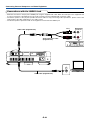
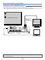
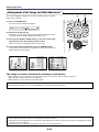
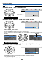
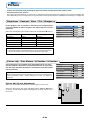
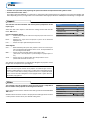
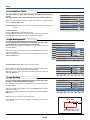
Connections with Component Signals
When the Video Equipment Has a YCbCr Connector or YPbPr Connector
• Make connections to the RGB connector of the projector using a component cable, which is available separately.
• The projector has been set to "Auto" at the factory; however, if it does not project, please change the input setting to "Compo-
nent" using the menu sequence of [Setup] → [Input Format] → [RGB].
See "Input Format" on Page E-49.
• This projector automatically distinguishes the YCbCr input signal and the YPbPr input signal and projects it.
When projecting the YCbCr signal or YPbPr signal, if the color of the overall image strongly leans toward being greenish or
another color, change the setting under the menu of [Color] → [Color Space].
See "Color Space" on Page E-45.
• Press the RGB button for input selection using the remote control.
RGBDVI
CrCbY
PrPbY
COMPONENT
COMPONENT
Component cable (Available as an option)
Order code: 28-690
Component cable (Available as an option)
Order code: 28-690
Green
Blue
Red
Green
Blue
Red
Page is loading ...
Page is loading ...
Page is loading ...
Page is loading ...
Page is loading ...
Page is loading ...
Page is loading ...
Page is loading ...
Page is loading ...
Page is loading ...
Page is loading ...
Page is loading ...
Page is loading ...
Page is loading ...
Page is loading ...
Page is loading ...
Page is loading ...
Page is loading ...
Page is loading ...
Page is loading ...
Page is loading ...
Page is loading ...
Page is loading ...
Page is loading ...
Page is loading ...
Page is loading ...
Page is loading ...
Page is loading ...
Page is loading ...
Page is loading ...
Page is loading ...
Page is loading ...
Page is loading ...
Page is loading ...
Page is loading ...
Page is loading ...
Page is loading ...
Page is loading ...
Page is loading ...
Page is loading ...
Page is loading ...
Page is loading ...
Page is loading ...
Page is loading ...
Page is loading ...
Page is loading ...
Page is loading ...
Page is loading ...
-
 1
1
-
 2
2
-
 3
3
-
 4
4
-
 5
5
-
 6
6
-
 7
7
-
 8
8
-
 9
9
-
 10
10
-
 11
11
-
 12
12
-
 13
13
-
 14
14
-
 15
15
-
 16
16
-
 17
17
-
 18
18
-
 19
19
-
 20
20
-
 21
21
-
 22
22
-
 23
23
-
 24
24
-
 25
25
-
 26
26
-
 27
27
-
 28
28
-
 29
29
-
 30
30
-
 31
31
-
 32
32
-
 33
33
-
 34
34
-
 35
35
-
 36
36
-
 37
37
-
 38
38
-
 39
39
-
 40
40
-
 41
41
-
 42
42
-
 43
43
-
 44
44
-
 45
45
-
 46
46
-
 47
47
-
 48
48
-
 49
49
-
 50
50
-
 51
51
-
 52
52
-
 53
53
-
 54
54
-
 55
55
-
 56
56
-
 57
57
-
 58
58
-
 59
59
-
 60
60
-
 61
61
-
 62
62
-
 63
63
-
 64
64
-
 65
65
-
 66
66
-
 67
67
-
 68
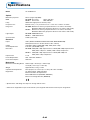
68


Plus Data Projector User manual
- Category
- Data projectors
- Type
- User manual
- This manual is also suitable for
Ask a question and I''ll find the answer in the document
Finding information in a document is now easier with AI
Related papers
-
PLUS Vision U4-232h User manual
-
Plus V-332 User manual
-
Epson U7-132h User manual
-
-
PLUS Vision PLUS U4-131 User manual
-
-
-
PLUS Vision U5-112 User manual
-
-
Other documents
-
 rapidline Typhoon Operating instructions
-
Mitsubishi Electric XD80 User manual
-
Mitsubishi XD70U User manual
-
-
-
-
-
-
-
