
SAFETY GUIDELINES
ASSEMBLY
OPERATION
MAINTENANCE
TROUBLESHOOTING
REPAIR PARTS
IMPORTANT:
Read the Safety Guidelines
and All Instructions Carefully
Before Operating
Sold by Sears Canada, Inc., Toronto, Ont. M5B 2B8
Model No.
919.725120
Record in the spaces provided.
(1) The Model Number can be found on
the maintenance label on top of the
motor shroud or on the bar code label
on the rear of air tank.
(2) The Date Code Number can be found
on the bar code label on the rear of the
air tank.
(3) The Serial Number can be found on the
bar code label on the rear of the tank.
(4) The Tank Registration Number is
located on the metal data plate which
is welded onto the backside of the air
tank. (This data plate is painted the
same color as the tank.)
Retain these numbers for future reference.
Model No________________________
Serial No________________________
Date Code_______________________
Tank Registration No______________
MGP-725120 4/12/96
OWNERS MANUAL FOR
CRAFTSMAN
PERMANENTLY LUBRICATED
TANK MOUNTED
AIR COMPRESSOR
CRAFTSMAN

2
TABLE OF CONTENTS
FULL ONE YEAR WFULL ONE YEAR W
FULL ONE YEAR WFULL ONE YEAR W
FULL ONE YEAR W
ARRANTY ON AIR COMPRESSORARRANTY ON AIR COMPRESSOR
ARRANTY ON AIR COMPRESSORARRANTY ON AIR COMPRESSOR
ARRANTY ON AIR COMPRESSORS
If this air compressor fails due to a defect in material or workmanship within one year from the date of
purchase, RETURN IT TO THE NEAREST SEARS SERVICE CENTER THROUGHOUT CANADA AND
SEARS WILL REPAIR IT, FREE OF CHARGE.
If this air compressor is used for commercial or rental purposes, the warranty will apply for ninety days
(90) from the date of purchase.
This Craftsman Air Compressor warranty gives you specific legal rights and you may have other rights
which vary from province to province.
Sears Canada, Inc., Toronto, Ont. M5B 2B8
WARRANTY ..........................................................................................................................2
SAFETY GUIDELINES ..........................................................................................................3
WARNING CHART ................................................................................................................ 3
GENERAL INFORMATION....................................................................................................5
GLOSSARY ...........................................................................................................................5
SPECIFICATION CHART ......................................................................................................5
DESCRIPTION OF OPERATION .......................................................................................... 6
TOOLS NEEDED FOR ASSEMBLY ......................................................................................6
ASSEMBLY............................................................................................................................7
INSTALLATION AND BREAK-IN PROCEDURES.................................................................7
Location of Air Compressor..............................................................................................7
Lubrication and Oil ...........................................................................................................7
Grounding Instructions .....................................................................................................7
Voltage and Circuit Protection..........................................................................................8
Extension Cords...............................................................................................................8
Break-in Procedure ..........................................................................................................8
OPERATING PROCEDURES ...............................................................................................9
MAINTENANCE.....................................................................................................................10
Air Filter - Inspection and Replacement...........................................................................10
Check Valve -Replacement..............................................................................................10
Safety Valve - Inspection ................................................................................................. 10
Motor................................................................................................................................10
Storage.............................................................................................................................10
TROUBLESHOOTING GUIDE ..............................................................................................11
AIR COMPRESSOR DIAGRAM ............................................................................................13
COMPRESSOR PUMP DIAGRAM........................................................................................15
HOW TO ORDER REPAIR PARTS .......................................................................................18
Page

3
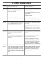
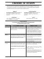
Flammable
It is normal for the motor and pressure switch to
spark when compressor starts or stops. A spark
can ignite vapors from gasoline or solvents,
causing a fire or explosion.
Air Tank
Modifications to air compressor components in an
attempt to reach higher air pressure can cause the
air tank to rupture or explode.
Never replace the air tank with a different model or
a larger tank. Return to Sears Service Center if
replacement is required.
Never drill into, weld or in any way modify the air
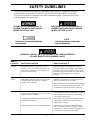
WHAT TO
LOOK FOR
Information for preventing damage
to equipment.
URGENT SAFETY INFORMATION - A
HAZARD THAT WILL CAUSE SERIOUS
INJURY OR LOSS OF LIFE.
IMPORTANT SAFETY INFORMATION - A
HAZARD THAT
MIGHT
CAUSE SERIOUS
INJURY OR LOSS OF LIFE.
HAZARDS CAN OCCUR IF EQUIPMENT IS NOT USED PROPERLY.
PLEASE READ THE FOLLOWING CHART.
WHAT COULD HAPPEN
HOW TO PREVENT IT
Vapors
Do not adjust, remove or tamper with the safety
valve or pressure switch. If safety valve or pressure
switch replacement is necessary, a part with the
same ratings must be used.
Incompatibility between tank and compressor will
cause the tank to rupture.
Modifications to the air tank will cause it to weaken.
Hot Parts
The metal compressor components, such as
manifold , tubes, etc. become hot when the air
compressor is running. If you touch them, you
may be seriously burned.
Avoid contact with metal components of the
compressor during or immediately after operation.
Reaching under or removing portions of the plastic
enclosures such as the console cover exposes hot
surfaces. Allow compressor to cool prior to
servicing.
If spraying a flammable material, provide ample
ventilation. Never spray in a closed area. There
must be a flow of fresh air at all times.
Always operate the air compressor in well-ventilated
areas, free of gasoline or other solvent vapors. Do
not operate the compressor near the spray area.
SAFETY GUIDELINES
tank. The tank may rupture or explode. If leaks
develop due to corrosion or tank is damaged, return
to Sears Service Center for replacement.
This manual contains information that is important for you to know and understand. This infor-
mation relates to protecting YOUR SAFETY and PREVENTING EQUIPMENT PROBLEMS.
To help you recognize this information, we use the following symbols. Please read the manual
and pay attention to these sections.
NOTE
Information that you should pay
special attention to.

4
SAFETY GUIDELINES
WHAT TO
LOOK FOR
Compressed air can propel dust, dirt or loose
particles. These propelled particles may cause
serious injury or damage.
WHAT COULD HAPPEN HOW TO PREVENT IT
Too much air pressure applied to air tools or
accessories can cause damage or risk of bursting.
Compressed
Air
Your air compressor is powered by electricity. Like
any other electrically powered device, if it is not
used properly it may cause electrical shock.
Always unplug the air compressor prior to mainte-
nance or repair.
Never use the air compressor outdoors when it is
raining.
Always plug the cord into an electrical outlet with
the specified voltage and adequate fuse protection.
The solvents 1,1,1 - Trichloroethane and Methylene
Chloride can chemically react with aluminum used
in paint spray guns, paint pumps, etc., and cause
an explosion. These solvents can also react with
galvanized components and cause corrosion and
weakening of parts. This does not affect your air
compressor - but it may affect the equipment being
used.
If the material you intend to spray contains the
solvents listed at left (read the label or data sheet),
do not use accessories that contain aluminum or
galvanized parts. You must either change the
material you intend to spray, or use only stainless
steel spray equipment.
Certain materials you are spraying (like paint, weed
killer, sand or insecticide) can be harmful if you
inhale them.
Unsuitable
Solvents
It is normal for compressed air to contain toxic or
irritating vapors. Such vapors are harmful if
inhaled.
Toxic Vapors
Electricity
Never directly inhale the compressed air produced
by this unit.
Read labels and safety data for all materials you
spray. Follow all safety precautions.
Use a mask or respirator if there is a chance of
inhaling toxic sprayed materials. Masks and
respirators have limits and will only provide protec-
tion against some kinds and limited amounts of
toxic material. Read mask and respirator instruc-
tions carefully. Consult with a safety expert or
industrial hygienist if you are not sure about the use
of a certain mask or respirator.
Check the manufacturer’s pressure rating for air
tools and accessories. Regulator outlet pressure
must never exceed the maximum pressure rating.
Never point any nozzle or sprayer toward a person
or any part of the body.
Always wear safety goggles or glasses when using
the air compressor.
Always turn the air compressor off before attaching
or removing accessories.

5
GENERAL INFORMATION
GLOSSARY
and inflator kits. An air pressure regulator is required for
most of the applications.
An inline air filter which removes moisture and dirt from
compressed air should be used where applicable.
An inline regulator can be used if a more precise adjust-
ment of air pressure is needed downstream.
CFM: Cubic Feet per Minute.
SCFM: Standard Cubic Feet per Minute; a unit of measure
of air delivery.
PSI: Pounds per Square Inch; a unit of measure of pres-
sure.
ASME: American Society of Mechanical Engineers; made,
tested, inspected and registered to meet the standards of
the ASME.
Cut-In Pressure: While the motor is off, air tank pressure
drops as you continue to use your accessory. When the tank
pressure drops to a certain low level and the pressure switch
lever is in "Auto", the motor will restart automatically. The
low pressure at which the motor automatically restarts is called
“cut-in pressure.”
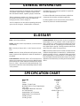
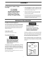
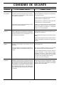
SPECIFICATION CHART
You have purchased an air compressor unit consisting of a
one cylinder, single-stage air compressor pump and air
tank. Included are wheels, regulator, gauges, and handle.
This air compressor requires no oil. Now you can enjoy all
the benefits of having an air compressor without ever
having to purchase, add or change oil.
Your air compressor can be used for operating paint spray
guns, air tools, blow guns, nailers/staplers, air brushes,
Model No.
Bore
Stroke
Voltage - Single Phase
Minimum Branch Circuit Requirement
Fuse Type
Amperage at Maximum Pressure
Air Tank
/
Capacity
Approximate Cut-in Pressure
Approximate Cut-out Pressure
SCFM @ 40 psi
SCFM @ 90 psi
919.725120
2 3/8"
1.35"
120
15 amps
Time Delay
15.0
ASME
/
12 gal. (U.S.)
100
125
4.7
3.3
Cut-Out Pressure: When you turn on your air compressor
and it begins to run, air pressure in the air tank begins to
build. It builds to a certain high pressure before the motor
automatically shuts off - protecting your air tank from pres-
sure higher than its capacity. The high pressure at which the
motor shuts off is called “cut-out pressure.”
CSA: Electrical products sold in Canada are required to be
certified to the applicable CSA standard (s). Canadian Stan-
dards Association (CSA) is a standards writing and safety
testing organization. Products that are CSA certified have
been evaluated and tested and found to meet or exceed the
applicable CSA standard (s) for safety and electrical perfor-
mance.

6
Air Compressor Pump: To compress air, the piston moves
up and down in the cylinder. On the downstroke, air is drawn
in through the air intake valves. The exhaust valves remain
closed. On the upstroke of the piston, air is compressed.
The intake valves close and compressed air is forced out
through the exhaust valves, through the outlet tube, through
the check valve and into the air tank.
Check Valve: When the air compressor is operating, the
check valve is “open”, allowing compressed air to enter the
air tank. When the air compressor reaches “cut-out” pres-
sure, the check valve “closes”, allowing air pressure to re-
main inside the air tank.
Pressure Switch: The pressure switch is fitted with a small
lever. It is labeled "Auto/O" for automatic run or off. In the
"O" position, the motor will not run. In the "Auto" position, it
automatically starts the motor when the air tank pressure
drops below the factory set “cut-in” pressure. It stops the
motor when the air tank pressure reaches the factory set
“cut-out” pressure.
Pressure Release Valve: The pressure release valve lo-
cated on the side of the pressure switch is designed to auto-
matically release compressed air trapped within the com-
pressor head and outlet tube. This short release of air will
occur when the air compressor reaches "cut-out" pressure
or the unit is shut off. If the air is not released, the motor will
not be able to start when next required.
Flow Valve: The flow valve allows air to flow from the head
as the motor is getting “up to speed”. Once the motor reaches
normal operating speed, the flow valve closes and the pump
begins to compress air, thus requiring less amp draw on ini-
tial start.
Safety Valve: If the pressure switch does not shut off the air
compressor at its cut-out pressure setting, the safety valve
will protect the tank against high pressure by “popping out”
at its factory set pressure (slightly higher than the pressure
switch cut-out setting).
Tools Needed for Assembly
• a 9/16" socket and an open end wrench for attaching the
wheels
• a 3/8" open end wrench or socket to tighten handle
screws
Regulator: The air pressure coming FROM the air tank is
controlled by the regulator. The regulator control knob is a
vibration proof design. Lift the regulator knob to engage
and depress the knob to lock. Turn the regulator knob clock-
wise to increase pressure and counter-clockwise to decrease
pressure. To avoid minor readjustment after making a change
in pressure setting, always approach the desired pressure
from a lower pressure. When reducing from a higher to a
lower setting, first reduce to some pressure less than that
desired, then bring up to the desired pressure. Depending
on the air requirements of each particular accessory, the outlet
regulated air pressure may have to be adjusted while oper-
ating the accessory.
Regulator Gauge: The outlet pressure gauge indicates the
air pressure available at the outlet side of the regulator. This
pressure is controlled by the regulator and is always less
than or equal to the tank pressure. See “Operating Proce-
dures”.
Tank Pressure Gauge: The tank pressure gauge indicates
the reserve air pressure in the tank.
Cooling System: This compressor contains an advanced
design cooling system. At the heart of this cooling system is
an engineered fan. It is perfectly normal for this fan to blow
air through the vent holes in large amounts. You know that
the cooling system is working when air is being expelled.
Drain Valve: This valve is located at the bottom of the tank.
To drain accumulated moisture from the tank, pull on the
safety valve until tank pressure is 15 PSI. Unscrew the drain
valve and allow the water to drain.
DESCRIPTION OF OPERATION

7
ASSEMBLY
BREAK-IN PROCEDURES
If repairing or replacing cord or plug, the grounding wire
must be kept separate from the current-carrying wires.
Never connect the grounding wire to a flat blade plug ter-
minal. The grounding wire has insulation with an outer sur-
face that is green with or without yellow stripes.
If these grounding instructions are not completely under-
stood, or if in doubt as to whether the compressor is prop-
erly grounded, have the installation checked by a qualified
electrician.
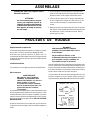
1. Attach the handle to the compressor saddle by inserting
the handle
inside
the compressor saddle and lining up
the two bolt holes on each side. Install the four screws,
two on each side. Tighten securely.
2. Install one shoulder bolt and one nut for each wheel.
Tighten securely. The compressor will sit level if the
wheels are properly installed.
3. Clean and dry underside of air tank leg opposite wheels.
Remove the protective paper strip from the adhesive
backed rubber foot strip. Attach the rubber foot strip to
the bottom of leg. Press firmly into place.
THE WHEELS AND HANDLE DO NOT
PROVIDE ADEQUATE CLEARANCE,
STABILITY OR SUPPORT FOR
PULLING THE UNIT UP AND DOWN
STAIRS OR STEPS. THE UNIT MUST
BE LIFTED, OR PUSHED UP A RAMP.
This portable air compressor is equipped with a cord having
a grounding wire with an appropriate grounding plug. The
plug must be used with an outlet that has been installed and
grounded in accordance with all local codes and ordinances.
The outlet must have the same configuration as the plug. DO
NOT USE AN ADAPTER.
Inspect the plug and cord before each use. Do not use if
there are signs of damage.
IMPROPER GROUNDING CAN RESULT
IN ELECTRICAL SHOCK.
Do not modify the plug that has been
provided. If it does not fit the available
outlet, the correct outlet should be
installed by a qualified technician.
Installing Wheels, Handles, Rubber
Foot Strip
Locate the air compressor in a clean, dry and well ventilated
area. The air filter must be kept clear of obstructions which
could reduce air delivery of the air compressor. The air com-
pressor should be located at least 12" away from the wall or
other obstructions that will interfere with the flow of fresh
intake and cooling air.
Location of the Air Compressor
This unit needs no lubrication or oiling.
Lubrication and Oil
Grounding Instructions
RISK OF ELECTRICAL SHOCK. In the
event of a short circuit, grounding
reduces the risk of shock by provid-
ing an escape wire for the electric
current. This air compressor must be
properly grounded.

8
Break-in Procedure
Serious damage may result if the following
break-in instructions are not closely followed.
Voltage and Circuit Protection
Refer to page 5 (Specification Chart) for the voltage and
circuit protection requirements of your compressor. Use only
a fuse or circuit breaker that is the same rating as the branch
circuit the air compressor is operated on. If the compressor
is connected to a circuit protected by fuses, use only dual
element time delay fuses.
Extension Cords
It is preferable to use extra air hose instead of an extension
cord to avoid voltage drop and power loss to the motor,
and to prevent overheating.
If an extension cord must be used, be sure it is:
• 12 gauge (AWG) or heavier. (Wire size increases as
gauge number decreases. 10 AWG and 8 AWG may
also be used. DO NOT USE 14 OR 16 AWG.)
• a three-wire extension cord that has a three-connector
grounding plug, and a three-slot receptacle that will
accept the plug.
• no longer than 50 feet
• in good condition
This procedure is required only once, before the air com-
pressor is put into service.
1. Set the pressure switch "AUTO/O" lever in the
"O" position for "Off".
2. Plug the power cord into the correct branch circuit
receptacle.
3. Do not attach hose to outlet. Leave the outlet open to
the atmosphere.
4. Turn the regulator
clockwise
, opening it fully, to
prevent air pressure build-up in the tank.
5. Move the "AUTO/O" lever to "AUTO". The com-
pressor will start.
6. RUN THE COMPRESSOR FOR 15 MINUTES. Make
sure the regulator is open and there is no tank pressure
build-up.
7. After 15 minutes, close the regulator by turning it
counterclockwise
. The air tank will fill to cut-out
pressure and then the motor will stop.

9
1. Before attaching air hose or accessories, make sure
the "AUTO/O" lever is set to “O” and the air regulator
is closed.
2. Attach hose and accessories.
OPERATING PROCEDURES
TOO MUCH AIR PRESSURE CREATES A
HAZARDOUS RISK OF BURSTING. CARE-
FULLY FOLLOW STEPS 3 AND 5 BELOW
EACH TIME THE COMPRESSOR IS USED.
Compressed air from the outfit may
contain water condensation. Do not
spray unfiltered air at an item that
could be damaged. Some air operated
tools or devices may require filtered
air. Read the instructions for the air
tool or device.
3. Check the manufacturer’s maximum pressure rating
for air tools and accessories. The regulator outlet
pressure must never exceed the maximum pressure
rating.
4. Turn the "AUTO/O" lever to “AUTO” and allow tank
pressure to build. Motor will stop when tank pressure
reaches “cut-out” pressure.
5. Open the regulator by turning it clockwise. Adjust
the regulator to the correct pressure setting. Your
compressor is ready for use.
6. Always operate the air compressor in well-ventilated
areas; free of gasoline or other solvent vapors. Do not
operate the compressor near the spray area.
WHEN YOU ARE FINISHED:
7. Set the “AUTO/O” lever to “O”.
8. Turn the regulator
counterclockwise
and set the
outlet pressure to zero.
9. Remove the air tool or accessory.
10.Open the regulator and allow the air to slowly bleed
from the tank. Close the regulator when tank pressure
is approximately 20 psi.
11.Drain water from air tank.
NOTE:
If drain cock valve is plugged, release
all air pressure. The valve can then be
removed, cleaned, then reinstalled.
12. After the water has been drained, close the drain
valve. The air compressor can now be stored.
WATER WILL CONDENSE IN THE AIR
TANK. IF NOT DRAINED, WATER WILL
CORRODE AND WEAKEN THE AIR TANK
CAUSING A RISK OF AIR TANK RUPTURE.

10
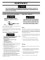
MAINTENANCE
ALL MAINTENANCE AND REPAIR OPERATIONS NOT LISTED MUST BE DONE BY A QUALIFIED SERVICE TECHNICIAN.
Air Filter - Inspection and Replacement
Hot surfaces. Risk of burn. Compressor
heads are exposed when filter cover is
removed. Allow compressor to cool prior to
servicing.
Filter
Filter Retainer
Keep the air filter clean at all times. Do not operate the com-
pressor with the air filter removed.
A dirty air filter will not allow the compressor to operate at full
capacity. Before you use the compressor, check the air filter
to be sure it is clean.
Check Valve Cleaning - Replacement
1. Release all air pressure from air tank and unplug outfit.
2. Remove shroud. (Key Nos. 1 and 2)
3. Loosen the top and bottom nuts and remove the outlet
tube. (Key Nos. 31, 33, and 34)
4. Remove the pressure release tube, fitting, and
connector. (Key Nos. 25, 26 and 27)
5. Unscrew the check valve (turn counterclockwise) using
a socket wrench. (Key No. 17)
6. Check that the valve disc moves freely inside the check
valve and that the spring holds the disc in the upper,
closed position. The check valve may be cleaned with a
solvent, such as paint and varnish remover.
7. Apply a Teflon based pipe sealant to the check valve
threads. Reinstall the check valve (turn clockwise).
8. Replace the pressure release tube and fitting.
9. Replace the outlet tube and tighten top and bottom nuts.
10.Replace the shroud.
If the safety valve does not work properly,
over-pressurization may occur, causing air tank
rupture or an explosion. Before starting com-
pressor, pull the ring on the safety valve to make
sure that the safety valve operates freely. If the
valve is stuck or does not operate smoothly, it
must be replaced with the same type of valve.
Risk of personal injury. Manifold assembly contains
compressed air which can be hazardous.
Manifold gets hot during operation.
Before servicing:
•Unplug or disconnect electrical supply
to compressor.
•Bleed tank of pressure.
•Allow compressor to cool.
Safety Valve - Inspection
Motor
The motor has an automatic reset thermal overload protector.
If the motor overheats for any reason, the overload protector
will shut off the motor. The motor must be allowed to cool
down before restarting. The compressor will automatically
restart after the motor cools.
If the overload protector shuts the motor off frequently, check
for a possible voltage problem. Low voltage can also be sus-
pected when:
1. The motor does not get up to full power or speed.
2. Fuses blow out when starting the motor; lights dim
and remain dim when motor is started and is running.
Storage
Before you store the air compressor, make sure you do the
following:
1. Review the Maintenance and “Operating Procedures”
sections and perform maintenance as necessary. Be
sure to drain water from the air tank.
2. Protect the electrical cord and air hose from damage
(such as being stepped on or run over). Wind them
loosely around the compressor handle.
Store the air compressor in a clean and dry location.
UNIT CYCLES AUTOMATICALLY WHEN POWER IS ON. WHEN DOING MAINTENANCE, YOU MAY BE EX-
POSED TO VOLTAGE SOURCES, COMPRESSED AIR OR MOVING PARTS. PERSONAL INJURIES CAN
OCCUR. BEFORE PERFORMING ANY MAINTENANCE OR REPAIR, UNPLUG THE COMPRESSOR AND
BLEED OFF ALL AIR PRESSURE.

11
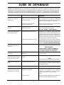
TROUBLESHOOTING GUIDE
PROBLEM
CAUSE
Excessive tank pressure - safety
valve pops off.
Air leaks at fittings or hose.
Air leaks at pressure switch
release valve.
Air leaks in air tank or at air tank
welds.
Air leaks between head and valve
plate.
Pressure reading on the regu-
lated pressure gauge drops when
an accessory is used.
Air leak from safety valve.
Knocking noise
Move the pressure switch lever to the “O”
position. If the compressor doesn’t shut off,
disconnect from the electrical outlet source
and return to a Sears Service Center to re-
place the pressure switch.
Return the compressor to Sears Service Cen-
ter to check and adjust, or replace switch.
Tighten fittings using teflon tape where air
can be heard escaping. Check fittings with
soapy water solution. DO NOT OVER-
TIGHTEN.
Return to Sears Service Center for replace-
ment of pressure switch.
Check to see if the pin in the bottom of the
pressure release valve is stuck. If it does not
move freely, return to the Service Center for
replacement of pressure switch.
A defective check valve results in a constant
air leak at the pressure release valve when
there is pressure in the tank and the com-
pressor is shut off. Remove and clean or re-
place check valve. DO NOT OVERTIGHTEN.
Air tank must be replaced. Do not repair the
leak. Return compressor to Sears Service
Center.
Torque head screws to 7-10 ft. lbs. If this
does not stop leak, replace seal.
If there is an excessive amount of pressure
drop when the accessory is used, adjust the
regulator.
NOTE
Adjust the regulated pressure under flow
conditions (while accessory is being used).
Operate safety valve manually by pulling
on ring. If valve still leaks, it should be
replaced .
Remove and clean, or replace.
CORRECTION
Pressure switch does not shut off
motor when compressor reaches
cut-out pressure.
Pressure switch cut-out too high.
Tube or hose fittings are not tight
enough.
Defective pressure switch release valve.
Defective or dirty check valve.
Defective air tank.
Leaking seal.
It is normal for some pressure drop
to occur.
Possible defect in safety valve.
Defective check valve.
DO NOT DRILL INTO, WELD OR OTHER-
WISE MODIFY AIR TANK OR IT WILL
WEAKEN. THE TANK CAN RUPTURE OR
EXPLODE.
PERFORMING REPAIRS MAY EXPOSE VOLTAGE SOURCES, MOVING PARTS OR COMPRESSED AIR
SOURCES. PERSONAL INJURY MAY OCCUR. PRIOR TO ATTEMPTING ANY REPAIRS, UNPLUG THE COM-
PRESSOR AND BLEED OFF TANK AIR PRESSURE.

12
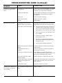
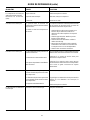
CORRECTION
CAUSE
Compressor is not supplying
enough air to operate acces-
sories.
TROUBLESHOOTING GUIDE (Continued)
Compressor is not large enough for
air requirement.
Possible defective motor or
capactior.
Check valve stuck open, putting
pressure on head.
Pressure release valve on pressure
switch has not unloaded head
pressure.
Paint spray on internal motor parts.
Broken exhaust valve.
Regulator knob continuous air
leak. Regulator will not shut
off at air outlet.
PROBLEM
Fuse blown, circuit breaker tripped. 1. Check fuse box for blown fuse and replace, if
necessary. Reset circuit breaker. Do not use a
fuse or circuit breaker with higher rating than
that specified for your particular branch circuit.
2. Check for proper fuse; only Time Delay fuses
are acceptable.
3. Check for low voltage conditions and/or
proper extension cord.
4. Disconnect the other electrical appliances
from circuit or operate the compressor on its
own branch circuit.
5. Check for loose electrical connections.
Return to Sears Service Center for inspection or
replacement, if necessary.
Bleed the line by pushing the lever on the pressure
switch to the "O" position; if the valve does not
open, replace it.
Inspect and replace if necessary.
Replace regulator.
Remove and clean, or replace the check valve.
Have compressor checked at Sears Service
Center. Do not operate the compressor in the paint
spray area. See flammable vapor warning.
Clean or replace air intake filter. Do not operate the
air compressor in any paint spray or drywall
sanding area.
Restricted air intake filter.
Check and replace if required.Hole in hose.
Check valve restricted. Remove and clean, or replace.
Tighten fittings.
Motor will not run or restart. Present tank pressure exceeds
pressure switch "cut-in" pressure.
Motor will start automatically when tank pressure
drops below "cut-in" pressure of pressure switch.
Check the accessory air requirement. If it is higher
than the SCFM or pressure supplied by your air
compressor, you need a larger compressor.
Air leaks.
Motor overload protection switch has
tripped.
Dirty or damaged regulator internal
parts.
Let motor cool off and overload switch will auto-
matically reset.

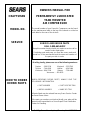
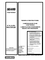
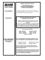
CRAFTSMAN
OWNERS MANUAL FOR
PERMANENTLY LUBRICATED
TANK MOUNTED
AIR COMPRESSOR
Sold By Sears Canada, Inc., Toronto, Ont. M5B 2B8
MODEL NO.
The model number of your Sears Air Compressor can be found
on the maintenance label on the top of the shroud or on the bar
code label on the rear of the air tank.
HOW TO ORDER
REPAIR PARTS
WHEN ORDERING REPAIR PARTS, ALWAYS GIVE THE
FOLLOWING INFORMATION:
• PART NUMBER • PART DESCRIPTION
• MODEL NUMBER • NAME OF ITEM
All parts listed may be ordered from any Sears Service Center
and most Sears stores.
If the parts you need are not stocked locally, your order will be
electronically transmitted to a Sears Repair Parts Distribution
Center for handling.
SERVICE
SERVICE AND REPAIR PARTS
CALL 1-800-665-4455*
Keep this number handy should you require a service call or
need to order repair parts.
If ordering parts make sure you have the name, make and
model no. of the merchandise and the name and number of
the part you wish to order.
*If calling locally, please use one of the following numbers:
Regina - 566-5124 Montreal - 333-5740
Toronto - 744-4900 Halifax - 454-2444
Kitchener - 894-7590 Ottawa - 738-4440
Vancouver - 420-8211
Page is loading ...
Page is loading ...
Page is loading ...
Page is loading ...
Page is loading ...
Page is loading ...
Page is loading ...
Page is loading ...
Page is loading ...
Page is loading ...
Page is loading ...
Page is loading ...
Page is loading ...
-
 1
1
-
 2
2
-
 3
3
-
 4
4
-
 5
5
-
 6
6
-
 7
7
-
 8
8
-
 9
9
-
 10
10
-
 11
11
-
 12
12
-
 13
13
-
 14
14
-
 15
15
-
 16
16
-
 17
17
-
 18
18
-
 19
19
-
 20
20
-
 21
21
-
 22
22
-
 23
23
-
 24
24
-
 25
25
-
 26
26


Ask a question and I''ll find the answer in the document
Finding information in a document is now easier with AI
in other languages
- français: Sears 919.72512 Manuel utilisateur
Related papers
Other documents
-
Craftsman 919.727320 Troubleshooting guide
-
-
Craftsman 919727320 Owner's manual
-
-
-
-
Craftsman Air Compressor Owner's manual
-
Makita MAC2200 Troubleshooting guide
-
-